EP0515931B1 - Drehkippbeschlag - Google Patents
Drehkippbeschlag Download PDFInfo
- Publication number
- EP0515931B1 EP0515931B1 EP92108266A EP92108266A EP0515931B1 EP 0515931 B1 EP0515931 B1 EP 0515931B1 EP 92108266 A EP92108266 A EP 92108266A EP 92108266 A EP92108266 A EP 92108266A EP 0515931 B1 EP0515931 B1 EP 0515931B1
- Authority
- EP
- European Patent Office
- Prior art keywords
- tilt
- pivot lever
- wing
- fitting
- turn fitting
- Prior art date
- Legal status (The legal status is an assumption and is not a legal conclusion. Google has not performed a legal analysis and makes no representation as to the accuracy of the status listed.)
- Expired - Lifetime
Links
Images

Classifications
-
- E—FIXED CONSTRUCTIONS
- E05—LOCKS; KEYS; WINDOW OR DOOR FITTINGS; SAFES
- E05F—DEVICES FOR MOVING WINGS INTO OPEN OR CLOSED POSITION; CHECKS FOR WINGS; WING FITTINGS NOT OTHERWISE PROVIDED FOR, CONCERNED WITH THE FUNCTIONING OF THE WING
- E05F7/00—Accessories for wings not provided for in other groups of this subclass
- E05F7/06—Devices for taking the weight of the wing, arranged away from the hinge axis
-
- E—FIXED CONSTRUCTIONS
- E05—LOCKS; KEYS; WINDOW OR DOOR FITTINGS; SAFES
- E05Y—INDEXING SCHEME ASSOCIATED WITH SUBCLASSES E05D AND E05F, RELATING TO CONSTRUCTION ELEMENTS, ELECTRIC CONTROL, POWER SUPPLY, POWER SIGNAL OR TRANSMISSION, USER INTERFACES, MOUNTING OR COUPLING, DETAILS, ACCESSORIES, AUXILIARY OPERATIONS NOT OTHERWISE PROVIDED FOR, APPLICATION THEREOF
- E05Y2201/00—Constructional elements; Accessories therefor
- E05Y2201/60—Suspension or transmission members; Accessories therefor
- E05Y2201/622—Suspension or transmission members elements
- E05Y2201/686—Rods, links
-
- E—FIXED CONSTRUCTIONS
- E05—LOCKS; KEYS; WINDOW OR DOOR FITTINGS; SAFES
- E05Y—INDEXING SCHEME ASSOCIATED WITH SUBCLASSES E05D AND E05F, RELATING TO CONSTRUCTION ELEMENTS, ELECTRIC CONTROL, POWER SUPPLY, POWER SIGNAL OR TRANSMISSION, USER INTERFACES, MOUNTING OR COUPLING, DETAILS, ACCESSORIES, AUXILIARY OPERATIONS NOT OTHERWISE PROVIDED FOR, APPLICATION THEREOF
- E05Y2600/00—Mounting or coupling arrangements for elements provided for in this subclass
- E05Y2600/10—Adjustable
- E05Y2600/30—Adjustment motion
- E05Y2600/32—Rotary motion
- E05Y2600/322—Rotary motion around a horizontal axis
-
- E—FIXED CONSTRUCTIONS
- E05—LOCKS; KEYS; WINDOW OR DOOR FITTINGS; SAFES
- E05Y—INDEXING SCHEME ASSOCIATED WITH SUBCLASSES E05D AND E05F, RELATING TO CONSTRUCTION ELEMENTS, ELECTRIC CONTROL, POWER SUPPLY, POWER SIGNAL OR TRANSMISSION, USER INTERFACES, MOUNTING OR COUPLING, DETAILS, ACCESSORIES, AUXILIARY OPERATIONS NOT OTHERWISE PROVIDED FOR, APPLICATION THEREOF
- E05Y2800/00—Details, accessories and auxiliary operations not otherwise provided for
-
- E—FIXED CONSTRUCTIONS
- E05—LOCKS; KEYS; WINDOW OR DOOR FITTINGS; SAFES
- E05Y—INDEXING SCHEME ASSOCIATED WITH SUBCLASSES E05D AND E05F, RELATING TO CONSTRUCTION ELEMENTS, ELECTRIC CONTROL, POWER SUPPLY, POWER SIGNAL OR TRANSMISSION, USER INTERFACES, MOUNTING OR COUPLING, DETAILS, ACCESSORIES, AUXILIARY OPERATIONS NOT OTHERWISE PROVIDED FOR, APPLICATION THEREOF
- E05Y2900/00—Application of doors, windows, wings or fittings thereof
- E05Y2900/10—Application of doors, windows, wings or fittings thereof for buildings or parts thereof
- E05Y2900/13—Type of wing
- E05Y2900/148—Windows
Definitions
- the invention relates to a tilt and turn fitting, in particular for windows with side links, according to the preamble of claim 1.
- EP 0 401 142 A 1 shows such a fitting.
- the lateral connection of the opening device and the upper pivot bearing is very unstable due to the necessary play in the articulation points, so that the window tends to hang in the area on the opening side.
- the connection leads at least to the fact that there is stiffness when changing the fitting from the tilting position to the turning position or from the rotating position to the locked position.
- EP 0 401 142 A1 proposes to use a relief element in the lower opening-side area in the form in which a roller is connected to the window sash, which roller cooperates on a run-up slope connected to the frame.
- a disadvantage of this form of training is that full relief is only achieved when the window is completely closed.
- the fitting is switched to the locked position, in which the seals are pretensioned via the locking pin of the fitting, the window sash is not yet completely relieved, so that there is still a risk of sluggishness at this time.
- GB-A 616 861 shows a locking bolt for a swinging door which engages behind a latch with its upper end and is supported in a support part via its lower end. This bar cannot disadvantageously ensure that it assumes a defined attachment position. In addition, it is not suitable for use with turn-tilt fittings.
- the invention has for its object to provide a relief element for a turn-tilt fitting according to the preamble of claim 1 such that a relief of the laterally arranged opening device and the upper pivot bearing takes place before the final installation of the window on the window frame.
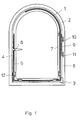
- the window sash 1 is supported with respect to the window frame 2 both in the rotating and in the tilted position by means of a tilt and turn joint 3.
- the fitting consists of faceplate 4 and drive rod 5.
- the drive rod is moved by means of a lever 6 via a gear and actuates locking and actuating elements by means of different units.
- An opening device 9 is arranged between the pivot-side wing leg 7 and the associated frame leg 8, which in turn is connected to the frame leg 8 via upper pivot bearings 10, 11.
- a relief element 12 is arranged in the lower opening-side area between sash 1 and frame 2.
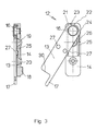
- the relief element 12 consists of a swivel lever 13, a fastening part 14 and a support part 15.
- the swivel lever 13 is rotatably connected to the fastening part 14 via a swivel joint 16.
- the swivel joint 16 can be designed as an eccentric bolt. This makes it possible to adjust the position between the pivot lever 13 and the fastening part 14, as a result of which manufacturing tolerances can be compensated for.
- the pivot lever 13 is supported in the stretched state with the support edge 30 on the support part 15 when the window sash 1 is closed or tilted.
- a side stop 17 guarantees a secure support.
- the fastening part 14 has at least one pin 18, which ensures the positive connection to the fastening rail 4 in a bore. Screws (not shown), which are screwed through bores 19, 20 into the window sash 1, serve to fasten the fastening part 14 and the faceplate 4.
- the support member 15 is also not shown holes and screws connected to the frame 2.
- FIG. 3 shows the pivot lever 13 and the fastening part 14 corresponding to FIG. 2. It can be seen that both parts have stops 21, 22, 23, 24 which limit the pivoting angle of the pivot lever 13 relative to the fastening part 14.
- a U-shaped spring 25 is arranged between the pivot lever 13 and the fastening part 14, which engages around the swivel joint 16 and lies with one leg in a groove 26 of the fastening part 14. The other leg of the spring 25 presses against an embossment 27 of the pivot lever 13 and thus causes pivoting into the engagement position, as shown in FIG. 3.
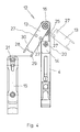
- FIG. 4 shows a special design of a relief element according to FIGS. 2 and 3.
- This relief element can optionally be used for use with a right-hand stop or a left-hand stop of the rotary tilt joint.
- the pivot lever 13 has two side stops 28, 29.
- the support edge 30 arranged between these side stops is supported on a projection 31 of the support part 15 when the window is closed.
- the right broken illustration of the pivot lever 13 represents the reversal position.
- embossments 27 are supported against the respective leg of the spring 25.
- each spring leg must be arranged freely resilient inside.
Landscapes
- Window Of Vehicle (AREA)
- Hinges (AREA)
- Closing And Opening Devices For Wings, And Checks For Wings (AREA)
- Specific Sealing Or Ventilating Devices For Doors And Windows (AREA)
- Switches With Compound Operations (AREA)
- Preparation Of Compounds By Using Micro-Organisms (AREA)
- Wing Frames And Configurations (AREA)
Description
- Die Erfindung betrifft einen Drehkippbeschlag, insbesondere für Fenster mit Seitenlenker, nach dem Oberbegriff des Anspruchs 1.
- Beim Einsatz von Drehkippbeschlägen beispielsweise für Fenster, die an ihrer Oberseite bogenförmig oder schräg auslaufen, kann in diesem Bereich kein Lenker zur Begrenzung der Kippbewegung eingesetzt werden. Bei derartigen Fenstern wird eine Ausstellvorrichtung bandseitig eingesetzt, die üblicherweise darüber hinaus mit dem oberen Drehlager in Verbindung stehen.
- Die EP 0 401 142 A 1 zeigt einen derartig ausgebildeten Beschlag. Die seitliche Anbindung der Ausstellvorrichtung und des oberen Drehlagers gestaltet sich aufgrund des notwendigen Spieles in den Gelenkpunkten sehr labil, so daß das Fenster dazu neigt, im öffnungsseitigen Bereich zu hängen. Die Anbindung führt im mindesten dazu, daß eine Schwergängigkeit beim Umstellen des Beschlages von der Kipp- in die Dreh- bzw. von der Drehin die Verschlußstellung besteht.
- Um den vorbeschriebenen Nachteil auszugleichen, schlägt die EP 0 401 142 A 1 vor, im unteren öffnungsseitigen Bereich ein Entlastungselement in der Form einzusetzen, als mit dem Fensterflügel eine Rolle verbunden ist, die auf einer mit dem Rahmen verbundenen Auflaufschräge zusammenwirkt.
- Nachteilig bei dieser Ausbildungsform ergibt sich jedoch, daß die volle Entlastung erst bei vollständigem Schließen des Fensters erreicht wird. Beim Umstellen des Beschlages in die Verschlußstellung, bei dem die Dichtungen über die Schließzapfen des Beschlages vorgespannt werden, ist der Fensterflügel noch nicht vollständig entlastet, so daß zu diesem Zeitpunkt weiterhin die Gefahr der Schwergängigkeit besteht.
- Die GB-A 616 861 zeigt einen Schließriegel für eine Schwenktür, der mit seinem oberen Ende hinter eine Falle greift und sich über sein unteres Ende in einem Stützteil abstützt. Bei diesem Riegel kann nachteilig nicht sichergestellt werden, daß er eine definierte Ansetzposition einnimmt. Darüber hinaus eignet er sich nicht zum Einsatz bei Drehkippbeschlägen.
- Der Erfindung liegt die Aufgabe zugrunde, ein Entlastungselement für einen Drehkippbeschlag nach dem Oberbegriff des Anspruchs 1 derartig auszubilden, daß bereits vor der endgültigen Anlage des Fensters am Fensterrahmen eine Entlastung der seitlich angeordneten Ausstellvorrichtung und des oberen Drehlagers erfolgt.
- Diese Aufgabe wird erfindungsgemäß durch die kennzeichnenden Merkmale des Anspruchs 1 gelöst. Vorteilhafte Weiterbildungen sind in den Ansprüchen 2 bis 6 beschrieben.
- Die mit einem Ausführungsbeispiel der Erfindung erzielten Vorteile bestehen insbesondere darin, daß das Entlastungselement direkt mit den Beschlagteilen verbunden ist und über dessen Befestigungselemente gehalten wird. Das Entlastungselement benötigt keinen zusätzlichen Bauraum und kann im vorhandenen Fensterfalz untergebracht werden.
- Ein Ausführungsbeispiel der Erfindung ist in der Zeichnung dargestellt und wird im folgenden näher beschrieben. Es zeigen
- Fig. 1 die systematische Darstellung eines Drehkippbeschlages mit einer seitlich angeordneten Ausstellvorrichtung für ein Rundbogenfenster,
- Fig. 2 den unteren öffnungsseitigen Bereich eines derartigen Fensters,
- Fig. 3 ein einseitig wirkendes Entlastungselement und
- Fig. 4 ein beidseitig wirkendes Entlastungselement.
- Bei einem Rundbogenfenster stützt sich der Fensterflügel 1 gegenüber dem Fensterrahmen 2 sowohl in Dreh- als auch in Kippstellung über ein Drehkippgelenk 3 ab. Der Beschlag besteht aus Stulpschiene 4 und Treibstange 5. Die Treibstange wird mittels eines Hebels 6 über ein Getriebe verschoben und betätigt mittels unterschiedlicher Einheiten Verriegelungs- und Betätigungselemente. Zwischen dem schwenkseitigen Flügelschenkel 7 und dem zugehörigen Rahmenschenkel 8 ist eine Ausstellvorrichtung 9 angeordnet, die wiederum über obere Drehlager 10, 11 mit dem Rahmenschenkel 8 verbunden ist.
- Im unteren öffnungsseitigen Bereich ist zwischen Flügel 1 und Rahmen 2 ein Entlastungselement 12 angeordnet. Das Entlastungselement 12 besteht aus einem Schwenkhebel 13, einem Befestigungsteil 14 und einem Stützteil 15. Der Schwenkhebel 13 ist drehbeweglich über ein Drehgelenk 16 mit dem Befestigungsteil 14 verbunden. Das Drehgelenk 16 kann, wie in Fig. 2 gezeigt, als Exzenterbolzen ausgebildet sein. Dadurch ist eine Lageverstellung zwischen Schwenkhebel 13 und Befestigungsteil 14 möglich, wodurch Fertigungstoleranzen ausgeglichen werden können. Der Schwenkhebel 13 stützt sich im gestreckten Zustand bei geschlossenem oder gekippten Fensterflügel 1 mit seiner Stützkante 30 auf dem Stützteil 15 ab. Ein Seitenanschlag 17 garantiert die sichere Auflage. Das Befestigungsteil 14 weist wenigstens einen Zapfen 18 auf, der in einer Bohrung der Befestigungsschiene 4 für die formschlüssige Verbindung mit dieser sorgt. Zur Befestigung des Befestigungsteils 14 und der Stulpschiene 4 dienen nicht dargestellte Schrauben, die durch Bohrungen 19, 20 in den Fensterflügel 1 eingeschraubt werden. Das Stützteil 15 wird über ebenfalls nicht dargestellte Bohrungen und Schrauben mit dem Rahmen 2 verbunden.
- Fig. 3 zeigt den Schwenkhebel 13 und das Befestigungsteil 14 entsprechend Fig. 2. Es ist erkennbar, daß beide Teile Anschläge 21, 22, 23, 24 aufweisen, die den Schwenkwinkel des Schwenkhebels 13 gegenüber dem Befestigungsteil 14 begrenzen. Zwischen Schwenkhebel 13 und Befestigungsteil 14 ist eine U-förmig gebogene Feder 25 angeordnet, die das Drehgelenk 16 umgreift und mit einem Schenkel in einer Nut 26 des Befestigungsteils 14 liegt. Der andere Schenkel der Feder 25 drückt gegen eine Prägung 27 des Schwenkhebels 13 und bewirkt damit ein Verschwenken in Eingriffsstellung, wie sie in Fig. 3 dargestellt ist.
- Fig. 4 zeigt eine besondere Ausbildung eines Entlastungselements nach den Fig. 2 und 3. Dieses Entlastungselement kann wahlweise für den Einsatz bei Rechtsanschlag oder Linksanschlag des Drehkippgelenkes eingesetzt werden. Der Schwenkhebel 13 weist in dieser Ausbildung zwei Seitenanschläge 28, 29 auf. Die zwischen diesen Seitenanschlägen angeordnete Stützkante 30 stützt sich bei Schließen des Fensters auf einen Vorsprung 31 des Stützteils 15 auf. Die rechte abgebrochene Abbildung des Schwenkhebels 13 stellt die Umschlagstellung dar. Wiederum stützen sich Prägungen 27 gegen den jeweiligen Schenkel der Feder 25 ab. Bei dieser Ausbildung muß selbstverständlich jeder Federschenkel nach innen frei nachgiebig angeordnet sein.
-
- 1 Flügel
- 2 Rahmen
- 3 Drehkippgelenk
- 4 Stulpschiene
- 5 Treibstange
- 6 Hebel
- 7 Flügelschenkel
- 8 Rahmenschenkel
- 9 Ausstellvorrichtung
- 10 Drehlager
- 11 Drehlager
- 12 Entlastungselement
- 13 Schwenkhebel
- 14 Befestigungsteil
- 15 Stützteil
- 16 Drehgelenk
- 17 Seitenanschlag
- 18 Zapfen
- 19 Bohrung
- 20 Bohrung
- 21 Anschlag
- 22 Anschlag
- 23 Anschlag
- 24 Anschlag
- 25 Feder
- 26 Nut
- 27 Prägung
- 28 Seitenanschlag
- 29 Seitenanschlag
- 30 Stützkante
- 31 Vorsprung
Claims (6)
Applications Claiming Priority (2)
| Application Number | Priority Date | Filing Date | Title |
|---|---|---|---|
| DE4117407 | 1991-05-28 | ||
| DE4117407A DE4117407C2 (de) | 1991-05-28 | 1991-05-28 | Drehkippbeschlag |
Publications (3)
| Publication Number | Publication Date |
|---|---|
| EP0515931A1 EP0515931A1 (de) | 1992-12-02 |
| EP0515931B1 true EP0515931B1 (de) | 1995-12-06 |
| EP0515931B2 EP0515931B2 (de) | 2005-12-28 |
Family
ID=6432610
Family Applications (1)
| Application Number | Title | Priority Date | Filing Date |
|---|---|---|---|
| EP92108266A Expired - Lifetime EP0515931B2 (de) | 1991-05-28 | 1992-05-15 | Drehkippbeschlag |
Country Status (4)
| Country | Link |
|---|---|
| EP (1) | EP0515931B2 (de) |
| AT (1) | ATE131248T1 (de) |
| DE (2) | DE4117407C2 (de) |
| ES (1) | ES2035814T5 (de) |
Cited By (1)
| Publication number | Priority date | Publication date | Assignee | Title |
|---|---|---|---|---|
| EP2343429A2 (de) | 2010-01-12 | 2011-07-13 | Aug. Winkhaus GmbH & Co. KG | Abstützeinrichtung für einen gegen einen Rahmen schwenkbaren Flügel |
Families Citing this family (17)
| Publication number | Priority date | Publication date | Assignee | Title |
|---|---|---|---|---|
| DE4437179C1 (de) * | 1994-10-18 | 1996-03-07 | Bilstein August Gmbh Co Kg | Heber für einen Fenster- oder Türflügel |
| DE4439463C1 (de) | 1994-11-04 | 1996-06-05 | Bilstein August Gmbh Co Kg | Entlastungselement |
| DE19511929C1 (de) * | 1995-03-31 | 1996-05-23 | Weidtmann Wilhelm Kg | Dreh- und/oder Kipp-Beschlag für Fenster, Türen od. dgl. mit einem zwischen dem Flügel und dem Rahmen angeordneten Flügelheber |
| DE29512887U1 (de) * | 1995-08-10 | 1996-12-12 | Niemann, Hans Dieter, 50169 Kerpen | Beschlag für Türen oder Fenster |
| DE19718325C1 (de) * | 1997-04-30 | 1998-08-13 | Siegenia Frank Kg | Selbsttätig wirkende Justiervorrichtung |
| DE19839409C1 (de) | 1998-08-29 | 1999-10-07 | Roto Frank Ag | Niveauschaltsperre |
| FR2786527B1 (fr) * | 1998-11-26 | 2001-01-19 | Ferco Int Usine Ferrures | Dispositif de relevage pour chassis ouvrant de porte, fenetre ou analogue |
| DE19854718A1 (de) * | 1998-11-26 | 2000-05-31 | Winkhaus Fa August | Fenster- oder Türdrehkippbeschlag |
| DE19911893C2 (de) * | 1999-03-17 | 2002-05-08 | Siegenia Frank Kg | Beschlaganordnung |
| IT1309940B1 (it) * | 1999-12-02 | 2002-02-05 | Alban Giacomo Spa | Gruppo ausiliario di guida alla chiusura di ante di serramenti osimili. |
| DE50013933D1 (de) | 2000-01-12 | 2007-02-15 | Siegenia Aubi Kg | Fehlbedienungssicherung |
| DE20000246U1 (de) * | 2000-01-12 | 2000-03-30 | AUBI Baubeschläge GmbH, 54411 Hermeskeil | Fehlbedienungssicherung |
| DE20010653U1 (de) | 2000-06-21 | 2001-10-31 | Siegenia-Frank Kg, 57074 Siegen | Drehkippbeschlag |
| DE102005000144A1 (de) * | 2005-10-25 | 2007-05-10 | Aug. Winkhaus Gmbh & Co. Kg | Flügelheber für einen Treibstangenbeschlag |
| DE102011003428A1 (de) * | 2011-02-01 | 2012-08-02 | Aug. Winkhaus Gmbh & Co. Kg | Dreh-/Kipp-Beschlag |
| WO2016045113A1 (zh) * | 2014-09-28 | 2016-03-31 | 李增榜 | 一种平开悬挂窗 |
| DE102015003931B3 (de) | 2015-03-25 | 2015-11-12 | Siegenia-Aubi Kg | Gelenkbandanordnung |
Family Cites Families (8)
| Publication number | Priority date | Publication date | Assignee | Title |
|---|---|---|---|---|
| DE327608C (de) * | 1920-10-14 | Franz Werner | Selbsttaetiger Tuer- oder Fenstertraeger zur Vermeidung des Senkens von Tuer- oder Fensterfluegeln | |
| GB616861A (en) * | 1946-09-16 | 1949-01-27 | Thomas Waller Atkinson | Improvements in or relating to gates, doors, and like structures |
| DE2250840A1 (de) * | 1972-10-17 | 1974-04-25 | Weidtmann Fa Wilhelm | Vorrichtung fuer fenster, tueren od. dgl. mit am blendrahmen gehaltertem dreh-kippfluegel |
| DE2929382C2 (de) * | 1979-07-20 | 1984-03-29 | August Bilstein GmbH & Co KG, 5828 Ennepetal | Kippriegel-Verschlußbeschlag für Kipp-Schwenk-Fenster, -Türen o. dgl. |
| DE3246177C2 (de) * | 1982-01-30 | 1986-11-20 | August Bilstein GmbH & Co KG, 5828 Ennepetal | Seitenbeschlag für Dreh-Kipp-Fenster, -Türen od.dgl. |
| DE3429699C2 (de) * | 1983-10-22 | 1986-01-09 | Siegenia-Frank Kg, 5900 Siegen | Fehlbedienungssperre für Treibstangenbeschläge |
| DE3829053C2 (de) * | 1988-08-26 | 1994-02-17 | Winkhaus Fa August | Dreh-Beschlag oder Dreh-Kipp-Beschlag von Fenstern, Türen oder dergleichen |
| FR2647843B1 (fr) * | 1989-06-02 | 1991-08-16 | Ferco Int Usine Ferrures | Ferrure pour porte, fenetre ou analogue dont le chassis ouvrant est a recouvrement partiel du cadre dormant et a ouverture a l'italienne |
-
1991
- 1991-05-28 DE DE4117407A patent/DE4117407C2/de not_active Expired - Fee Related
-
1992
- 1992-05-15 ES ES92108266T patent/ES2035814T5/es not_active Expired - Lifetime
- 1992-05-15 AT AT92108266T patent/ATE131248T1/de active
- 1992-05-15 DE DE59204545T patent/DE59204545D1/de not_active Expired - Lifetime
- 1992-05-15 EP EP92108266A patent/EP0515931B2/de not_active Expired - Lifetime
Cited By (1)
| Publication number | Priority date | Publication date | Assignee | Title |
|---|---|---|---|---|
| EP2343429A2 (de) | 2010-01-12 | 2011-07-13 | Aug. Winkhaus GmbH & Co. KG | Abstützeinrichtung für einen gegen einen Rahmen schwenkbaren Flügel |
Also Published As
| Publication number | Publication date |
|---|---|
| DE59204545D1 (de) | 1996-01-18 |
| EP0515931B2 (de) | 2005-12-28 |
| EP0515931A1 (de) | 1992-12-02 |
| DE4117407A1 (de) | 1992-12-03 |
| ES2035814T1 (es) | 1993-05-01 |
| ES2035814T3 (es) | 1996-02-16 |
| ATE131248T1 (de) | 1995-12-15 |
| DE4117407C2 (de) | 1995-01-05 |
| ES2035814T5 (es) | 2006-07-01 |
Similar Documents
| Publication | Publication Date | Title |
|---|---|---|
| DE4117407C2 (de) | Drehkippbeschlag | |
| EP0977930B1 (de) | Beschlag mit tragarm oder ausstellarm zur lagerung eines drehflügels oder dreh-kippflügels | |
| DE2648344A1 (de) | Beschlag fuer schiebefenster, schiebetueren u.dgl. | |
| DE68903724T2 (de) | Beschlag fuer tuer, fenster oder dergleichen. | |
| DE3041399A1 (de) | Fenster kipp und spaltkipp | |
| DE1816581B2 (de) | Fluegelverschlussvorrichtung fuer fenster, tueren o.dgl. | |
| DE2460402B2 (de) | Ausstellvorrichtung für Drehkippflügel von Fenstern, Türen o.dgl. | |
| DE3844627A1 (de) | Mit verschlussmitteln ausgeruestetes fenster, tuer oder dergleichen | |
| EP0096744A2 (de) | Drehkippbeschlag | |
| DE69720311T2 (de) | Gelenkbeschlag, insbesondere ein Eckband für Türen, Fenster oder dergleichen | |
| EP0265606A2 (de) | Scharniergelenk für fenster, Türen od.dgl. | |
| DE2040525C3 (de) | Fenster oder Tür mit Flügel und Rahmen | |
| EP0531626B1 (de) | Beschlag für insb. zwangsweise kipp- und parallel abstellbare Flügel | |
| DE20102570U1 (de) | Drehkippbeschlag | |
| DE9117241U1 (de) | Drehkippbeschlag | |
| DE8103368U1 (de) | Drehkippfenster oder -tür | |
| DE20017814U1 (de) | Türscharnier | |
| DE19953774B4 (de) | Tür oder Fenster mit einem Tür- oder Fensterflügel und einem über dem Tür- oder Fensterflügel angeordneten Oberlichtöffner | |
| DE202005010513U1 (de) | Schwenktür mit einer Halterung zur Einspannung einer Glasscheibe und eine Duschabtrennung mit einer solchen Schwenktür | |
| DE60210362T2 (de) | Gelenkbeschlag für Flügel einer Tür oder eines Dreh- und/oder Drehkippfensters | |
| DE9409388U1 (de) | Dreh-Kipp-Beschlag für Fenster, Türen o.dgl. | |
| DE4333724A1 (de) | Fensterflügel oder dergleichen | |
| EP1715125A2 (de) | Drehkipp- bzw. Kippdrehfensterbeschlag mit Spaltlüftungsstellung | |
| EP1259691B1 (de) | Auflaufbock | |
| EP1581712A1 (de) | Beschlageinheit für ein fenster oder eine tür |
Legal Events
| Date | Code | Title | Description |
|---|---|---|---|
| PUAI | Public reference made under article 153(3) epc to a published international application that has entered the european phase |
Free format text: ORIGINAL CODE: 0009012 |
|
| AK | Designated contracting states |
Kind code of ref document: A1 Designated state(s): AT DE ES FR GB IT |
|
| 17P | Request for examination filed |
Effective date: 19921014 |
|
| GBC | Gb: translation of claims filed (gb section 78(7)/1977) | ||
| ITCL | It: translation for ep claims filed |
Representative=s name: RICCARDI SERGIO & CO. |
|
| EL | Fr: translation of claims filed | ||
| 17Q | First examination report despatched |
Effective date: 19941011 |
|
| GRAA | (expected) grant |
Free format text: ORIGINAL CODE: 0009210 |
|
| AK | Designated contracting states |
Kind code of ref document: B1 Designated state(s): AT DE ES FR GB IT |
|
| REF | Corresponds to: |
Ref document number: 131248 Country of ref document: AT Date of ref document: 19951215 Kind code of ref document: T |
|
| GBT | Gb: translation of ep patent filed (gb section 77(6)(a)/1977) |
Effective date: 19951207 |
|
| REF | Corresponds to: |
Ref document number: 59204545 Country of ref document: DE Date of ref document: 19960118 |
|
| ET | Fr: translation filed | ||
| REG | Reference to a national code |
Ref country code: ES Ref legal event code: FG2A Ref document number: 2035814 Country of ref document: ES Kind code of ref document: T3 |
|
| ITF | It: translation for a ep patent filed | ||
| PLBI | Opposition filed |
Free format text: ORIGINAL CODE: 0009260 |
|
| PLAV | Examination of admissibility of opposition |
Free format text: ORIGINAL CODE: EPIDOS OPEX |
|
| PLBQ | Unpublished change to opponent data |
Free format text: ORIGINAL CODE: EPIDOS OPPO |
|
| RAP2 | Party data changed (patent owner data changed or rights of a patent transferred) |
Owner name: AUBI BAUBESCHLAEGE GMBH |
|
| PLBI | Opposition filed |
Free format text: ORIGINAL CODE: 0009260 |
|
| PLBQ | Unpublished change to opponent data |
Free format text: ORIGINAL CODE: EPIDOS OPPO |
|
| 26 | Opposition filed |
Opponent name: SIEGENIA-FRANK KG Effective date: 19960622 |
|
| PLAV | Examination of admissibility of opposition |
Free format text: ORIGINAL CODE: EPIDOS OPEX |
|
| PLBI | Opposition filed |
Free format text: ORIGINAL CODE: 0009260 |
|
| PLBQ | Unpublished change to opponent data |
Free format text: ORIGINAL CODE: EPIDOS OPPO |
|
| 26 | Opposition filed |
Opponent name: SIEGENIA-FRANK KG Effective date: 19960622 Opponent name: WINKHAUS TECHNIK GMBH & CO. KG Effective date: 19960718 |
|
| PLAV | Examination of admissibility of opposition |
Free format text: ORIGINAL CODE: EPIDOS OPEX |
|
| PLBF | Reply of patent proprietor to notice(s) of opposition |
Free format text: ORIGINAL CODE: EPIDOS OBSO |
|
| 26 | Opposition filed |
Opponent name: GRETSCH-UNITAS GMBH, BAUBESCHLAEGE Effective date: 19960829 Opponent name: WINKHAUS TECHNIK GMBH & CO. KG Effective date: 19960718 Opponent name: SIEGENIA-FRANK KG Effective date: 19960622 Opponent name: ROTO FRANK AG Effective date: 19960903 |
|
| PLBF | Reply of patent proprietor to notice(s) of opposition |
Free format text: ORIGINAL CODE: EPIDOS OBSO |
|
| REG | Reference to a national code |
Ref country code: GB Ref legal event code: IF02 |
|
| RDAH | Patent revoked |
Free format text: ORIGINAL CODE: EPIDOS REVO |
|
| APAC | Appeal dossier modified |
Free format text: ORIGINAL CODE: EPIDOS NOAPO |
|
| APAC | Appeal dossier modified |
Free format text: ORIGINAL CODE: EPIDOS NOAPO |
|
| PLBP | Opposition withdrawn |
Free format text: ORIGINAL CODE: 0009264 |
|
| RAP2 | Party data changed (patent owner data changed or rights of a patent transferred) |
Owner name: SIEGENIA-AUBI KG |
|
| REG | Reference to a national code |
Ref country code: GB Ref legal event code: 732E |
|
| REG | Reference to a national code |
Ref country code: ES Ref legal event code: PC2A |
|
| RAP2 | Party data changed (patent owner data changed or rights of a patent transferred) |
Owner name: SIEGENIA-AUBI KG |
|
| PLBP | Opposition withdrawn |
Free format text: ORIGINAL CODE: 0009264 |
|
| APAA | Appeal reference recorded |
Free format text: ORIGINAL CODE: EPIDOS REFN |
|
| APBU | Appeal procedure closed |
Free format text: ORIGINAL CODE: EPIDOSNNOA9O |
|
| APAH | Appeal reference modified |
Free format text: ORIGINAL CODE: EPIDOSCREFNO |
|
| PUAH | Patent maintained in amended form |
Free format text: ORIGINAL CODE: 0009272 |
|
| STAA | Information on the status of an ep patent application or granted ep patent |
Free format text: STATUS: PATENT MAINTAINED AS AMENDED |
|
| 27A | Patent maintained in amended form |
Effective date: 20051228 |
|
| AK | Designated contracting states |
Kind code of ref document: B2 Designated state(s): AT DE ES FR GB IT |
|
| GBTA | Gb: translation of amended ep patent filed (gb section 77(6)(b)/1977) | ||
| REG | Reference to a national code |
Ref country code: ES Ref legal event code: DC2A Date of ref document: 20060316 Kind code of ref document: T5 |
|
| ET3 | Fr: translation filed ** decision concerning opposition | ||
| PLAB | Opposition data, opponent's data or that of the opponent's representative modified |
Free format text: ORIGINAL CODE: 0009299OPPO |
|
| PGFP | Annual fee paid to national office [announced via postgrant information from national office to epo] |
Ref country code: ES Payment date: 20110525 Year of fee payment: 20 Ref country code: FR Payment date: 20110607 Year of fee payment: 20 |
|
| PGFP | Annual fee paid to national office [announced via postgrant information from national office to epo] |
Ref country code: AT Payment date: 20110512 Year of fee payment: 20 Ref country code: GB Payment date: 20110520 Year of fee payment: 20 |
|
| PGFP | Annual fee paid to national office [announced via postgrant information from national office to epo] |
Ref country code: IT Payment date: 20110527 Year of fee payment: 20 Ref country code: DE Payment date: 20110520 Year of fee payment: 20 |
|
| REG | Reference to a national code |
Ref country code: DE Ref legal event code: R071 Ref document number: 59204545 Country of ref document: DE |
|
| REG | Reference to a national code |
Ref country code: DE Ref legal event code: R071 Ref document number: 59204545 Country of ref document: DE |
|
| REG | Reference to a national code |
Ref country code: GB Ref legal event code: PE20 Expiry date: 20120514 |
|
| PG25 | Lapsed in a contracting state [announced via postgrant information from national office to epo] |
Ref country code: DE Free format text: LAPSE BECAUSE OF EXPIRATION OF PROTECTION Effective date: 20120516 |
|
| PG25 | Lapsed in a contracting state [announced via postgrant information from national office to epo] |
Ref country code: GB Free format text: LAPSE BECAUSE OF EXPIRATION OF PROTECTION Effective date: 20120514 |
|
| REG | Reference to a national code |
Ref country code: AT Ref legal event code: MK07 Ref document number: 131248 Country of ref document: AT Kind code of ref document: T Effective date: 20120515 |
|
| REG | Reference to a national code |
Ref country code: ES Ref legal event code: FD2A Effective date: 20130718 |
|
| PG25 | Lapsed in a contracting state [announced via postgrant information from national office to epo] |
Ref country code: ES Free format text: LAPSE BECAUSE OF EXPIRATION OF PROTECTION Effective date: 20120516 |