EP0513744B1 - Magnetisches Aufzeichnungs- und Wiedergabegerät - Google Patents
Magnetisches Aufzeichnungs- und Wiedergabegerät Download PDFInfo
- Publication number
- EP0513744B1 EP0513744B1 EP92108009A EP92108009A EP0513744B1 EP 0513744 B1 EP0513744 B1 EP 0513744B1 EP 92108009 A EP92108009 A EP 92108009A EP 92108009 A EP92108009 A EP 92108009A EP 0513744 B1 EP0513744 B1 EP 0513744B1
- Authority
- EP
- European Patent Office
- Prior art keywords
- tape
- tension
- actuator
- head
- magnetic
- Prior art date
- Legal status (The legal status is an assumption and is not a legal conclusion. Google has not performed a legal analysis and makes no representation as to the accuracy of the status listed.)
- Expired - Lifetime
Links
Images









Classifications
-
- G—PHYSICS
- G11—INFORMATION STORAGE
- G11B—INFORMATION STORAGE BASED ON RELATIVE MOVEMENT BETWEEN RECORD CARRIER AND TRANSDUCER
- G11B15/00—Driving, starting or stopping record carriers of filamentary or web form; Driving both such record carriers and heads; Guiding such record carriers or containers therefor; Control thereof; Control of operating function
- G11B15/60—Guiding record carrier
- G11B15/602—Guiding record carrier for track selection, acquisition or following
-
- G—PHYSICS
- G11—INFORMATION STORAGE
- G11B—INFORMATION STORAGE BASED ON RELATIVE MOVEMENT BETWEEN RECORD CARRIER AND TRANSDUCER
- G11B15/00—Driving, starting or stopping record carriers of filamentary or web form; Driving both such record carriers and heads; Guiding such record carriers or containers therefor; Control thereof; Control of operating function
- G11B15/18—Driving; Starting; Stopping; Arrangements for control or regulation thereof
- G11B15/1808—Driving of both record carrier and head
- G11B15/1875—Driving of both record carrier and head adaptations for special effects or editing
-
- G—PHYSICS
- G11—INFORMATION STORAGE
- G11B—INFORMATION STORAGE BASED ON RELATIVE MOVEMENT BETWEEN RECORD CARRIER AND TRANSDUCER
- G11B15/00—Driving, starting or stopping record carriers of filamentary or web form; Driving both such record carriers and heads; Guiding such record carriers or containers therefor; Control thereof; Control of operating function
- G11B15/18—Driving; Starting; Stopping; Arrangements for control or regulation thereof
- G11B15/43—Control or regulation of mechanical tension of record carrier, e.g. tape tension
-
- G—PHYSICS
- G11—INFORMATION STORAGE
- G11B—INFORMATION STORAGE BASED ON RELATIVE MOVEMENT BETWEEN RECORD CARRIER AND TRANSDUCER
- G11B15/00—Driving, starting or stopping record carriers of filamentary or web form; Driving both such record carriers and heads; Guiding such record carriers or containers therefor; Control thereof; Control of operating function
- G11B15/18—Driving; Starting; Stopping; Arrangements for control or regulation thereof
- G11B15/46—Controlling, regulating, or indicating speed
- G11B15/467—Controlling, regulating, or indicating speed in arrangements for recording or reproducing wherein both record carriers and heads are driven
- G11B15/4673—Controlling, regulating, or indicating speed in arrangements for recording or reproducing wherein both record carriers and heads are driven by controlling the speed of the tape while the head is rotating
Definitions
- the present invention relates to a magnetic recording and reporducing apparatus according to the pre-characterizing part of claim 1.
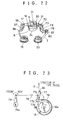
- Figure 22 shows the outline construction of a general tape driving system in a rotary head type magnetic recording and reproducing apparatus, such as video tape recorder (VTR) cited in "Jiki Kiroku Gijutsu Nyumon (Introduction of Magnetic Recording Technology)” (by Yokoyama, published by Sogo Denshi Shuppansha, page 187).
- VTR video tape recorder
- the path in this tape drive system through which the magnetic tape T travels consists of the following components: a supply reel 15 ; a back tension post 36 to detect the tension of the magnetic tape T running through the path; a full-width erase head 37 to erase the information recorded by the rotary head on at least a part of the magnetic tape T ; an impedance roller 55 and a guide roller 17 to stabilize the movement of the magnetic tape T ; an inclination post 18 to give a certain inclination to the magnetic tape T fed onto the circumference of the head cylinder D made up of an upper cylinder D 1 and a lower cylinder D 2 ; a circumferential edge of the head cylinder D having a rotary head (not seen in this figure because of the magnetic tape T obstructing the sight); an inclination post 20 to relieve the magnetic tape T leaving the head cylinder D of the inclination; a guide roller 21; an impedance roller 70; an erase head 73 to erase information including voice and control information recorded on the linear track formed parallel to the edge of the magnetic
- the magnetic tape T is gripped by the pinch roller 75 and the capstan 22 rotating at a specified speed and is pulled by the rotating force of the capstan 22 so that it is driven from the supply reel 15 through the back tension post 36 to the guide roller 80 and finally wound on the takeup reel 23 .
- the magnetic tape T is wound helically on the head cylinder D at a specified angle to allow the rotary head that rotates with the upper cylinder D 1 to magnetically record or reproduce information to/from the helical track on the tape.
- the recording and reproducing or erasing is also carried out by the full-width erase head 37 , erase head 73 and record and reproduce head 74 in addition to the rotary head. That is, when all the information to be recorded on the magnetic tape, such as the video signal, audio signal and control signal, is new, the information present in the full width of the magnetic tape T is erased by the full-width erase head 37 and then the video, audio and control signals are recorded by the rotary head and the record and reproduce head 74 . During the after-recording of voice or during the rewriting of only the control signal, only the linear track area of the magnetic tape is erased by the erase head 73 and then new voice and control information is recorded in the linear track by the record and reproduce head 74.
- the record format used in recording such video, audio and control signals in helical track or linear track can be made compatible with video signal recording schemes generally known as VHS and ⁇ systems and a digital voice signal recording scheme generally called DAT.
- high density recording and reproducing requires keeping the spacing between the magnetic head and the tape at a constant value. Further, to perform special reproduction such as high-speed replay and still replay without generating noise requires an additional control of making the magnetic head follow the recorded helical track.
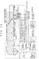
- Figure 23 shows an example of the back tension controller applied to the magnetic recording and reproducing apparatus of Figure 22.
- This back tension controller controls the back tension of the tape to keep the spacing constant.
- the force required to draw out the magnetic tape T from the supply reel 15 mounted on the supply reel mount 15a i.e., the back tension, is controlled to keep the tension of the magnetic tape T at a specified constant value.
- the supply reel 15 and the back tension post 36 are also shown in Figure 22.
- a band brake 76 with one end fixed is provided to the circumference of the supply reel mount 15a to restrict the rotation of the reel mount.
- the other end is engaged with a pin 77b on a tension control arm 77 that is pivotable about a shaft 77a.
- the other end of the tension control arm 77 opposite to the shaft 77a is fitted with the back tension post 36 with which the magnetic tape T engages.
- the intermediate portion of the tension control arm 77 is formed with a connector portion 77c, to which a tension spring 78 is attached at one end, with the other end connected to the tip of a tension adjust lever 79 .
- the tension adjust lever 79 can be rotated about its shaft 79a . By rotating the lever 79 to change the pulling force of the tension control arm 77 through the tension spring 78 , it is possible to adjust the reference tension of the tension controller.
- the basic or reference tension can be adjusted by rotating the adjust lever 79 , as mentioned above.
- the tension of the magnetic tape is adjusted by the mechanism described above to absorb moderate variations of the tape tension at the tape supply position, thereby holding the spacing between the magnetic tape and the head constant.
- Such a conventional system does not relate the spacing between the magnetic tape and the head to the tape tension in the control of the spacing.
- the control of the spacing at a constant value for securing the steady head contact is achieved by making the surface accuracy of the magnetic tape uniform and by performing a strict quality control during manufacturing process on the head cylinder's surface smoothness and the window shape as well as on the shape and the amount of projection of the magnetic head.
- control of the spacing making use of such a mechanical system may be applicable to systems that require only a low-frequency control range or not-so-high recording density.
- the above control method poses a problem when the line recording density is increased.
- the magnetic head tracing on the magnetic tape is done by keeping the tape speed and the rotating speed of the rotary head equal to those during the recording, so that the angle between the magnetic head trace and the edge of the magnetic tape becomes equal to the angle of the track being recorded.
- the replay is performed by changing only the magnetic tape speed from that during the recording, with the rotating speed of the rotary head set equal to that during the recording, the angle in which the magnetic head traces does not match the angle of the recording track, causing deviations from the track (or simply referred to as an inclination error) and therefore noise on the reproduced picture.
- the conventional auto-tracking reproducing apparatus which matches the locus of the magnetic head with that of the recording track normally has a video signal reproducing magnetic head mounted on an electro-mechanical conversion element (referred to as a head actuator).
- the head actuator drives the magnetic head in a direction perpendicular to or in a direction having a vertical component with respect to the movement of the recording track to make the magnetic head automatically trace the recording track.
- tracking error As is known with the 8mm VTR format, several kinds (four example, four) of low-frequency tracking pilot signal outside the video signal frequency band are superimposed on the video signal and recorded over several tracks (four tracks) so that different pilot signals are adjacent to each other. With this pilot signal method, a tracking error signal may be detected according to the difference in cross-talk level between the left and right tracks during the replay.
- the magnetic head is forcibly subjected to fine vibrations at a constant frequency or so-called wobbling frequency in the track width direction.
- the reproduction envelope signal from the magnetic head at this time is synchronously detected at the wobbling frequency to produce a tracking error signal.
- the reproduction envelope signal from the magnetic head is sample-held at the center of the field read out. Then, the voltage applied to the actuator or the rotating phase of the capstan motor is changed one step (for example, increased one step), and the envelope level of the frame is compared with the sample-held value. This series of operations is continued until the next frame envelope level is smaller.
- the conventional auto-tracking reproduction apparatus utilizes the above-mentioned various tracking error detection methods whereby tracking errors are detected and fed back to the head actuator incorporated in the head cylinder.
- Such movable heads are generally used not only for the DTF control to correct the tracking error at times of normal speed replay but also frequently used for special replays such as high-speed replay, slow replay and still replay.
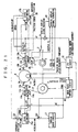
- Figure 24 shows the outline of a system, published in the National Technical Report Vol.28, No.3 (June, 1982), page 41, as one example case where such a movable head is applied for noiseless special replay.
- the rotating magnetic head H is driven by the head actuator 14 in a direction perpendicular to the direction of the tape travel.
- the reproduction envelope signal from the magnetic head H is fed to the tracking error detector 16 , which detects the amount of tracking error.
- the inclination correction pattern generator 18 uses the tape speed information from the frequency generator representing the rotating speed of the capstan to generate an inclination correction pattern that causes the magnetic head H to trace the track in such a way that the angle at which the magnetic head H scans over the tape is equal to the angle of the recording track.
- the tracking error signal from the tracking error detector 16 and the inclination correction pattern from the inclination correction pattern generator 18 are added up by an adder 410 to produce a head actuator drive signal that causes the magnetic head to move in the direction of the magnetic tape travel.
- the magnetic head H traces on the tape at an angle equal to the angle of the recording track.
- the angle at which the magnetic head H traces over the tape is not equal to the angle of the recording track, resulting in a track shift (referred to as an inclination error) and generating noise on the reproduced picture.
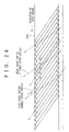
- Figure 26 and 27 show the relationship between the recording track pattern on the magnetic tape and the locus of the magnetic head.
- the rotating speed of the rotary head remains the same as that during the recording.
- the tape is driven in the forward direction in Figure 26 and in the backward direction in Figure 27 , at a 5-times replay speed, which means the tape is driven and replayed at 5 times the recording speed.
- Reference numeral A in Figure 26 shows the locus of the magnetic head at times of recording and normal replay.
- the angle of the magnetic head locus becomes large as shown at B so that the magnetic head crosses five tracks (1)-(5) in the same period that it crosses the magnetic tape widthwise.
- Figure 27 shows the locus of the magnetic head when the magnetic tape is driven at 5 times the normal replay speed in a direction reverse to the locus of the magnetic head that was described during the normal replay. It describes a locus C that intersects the tracks -(1) to -(5) at a small angle.
- the loci B, C must be corrected so that they trace the recorded tracks.
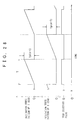
- Figure 28 shows the outline of inclination error patterns produced in a so-called guard bandless recording scheme VTR which separates signals of adjacent tracks from each other that have no space therebetween.
- VTR guard bandless recording scheme
- the inclination error during the n-times speed replay is given by tp(n-1) .
- the value of the inclination error is expressed as a function that has a replay speed ratio n as a parameter. In other words, the inclination error changes according to the tape travel speed.
- the inclination correction pattern generator 18 in Figure 25 may use, for example, an FG signal from the capstan frequency generator as the tape speed information to generate the inclination correction pattern.
- the locus of the magnetic head H is corrected in its inclination so that the magnetic head moves parallel to the recorded track even during replay at other than the normal replay speed.
- the control methods for the auto-tracking control system include the pilot scheme, wobbling scheme and mountain climbing scheme. To produce a quality picture even during replay at other than normal replay speed, it is necessary to make the magnetic head follow the non-linearity of the recorded track (track bend). It is therefore preferred that the pilot scheme and wobbling scheme that can offer relatively wide control frequency range be adopted.
- the control method and operation of the auto-tracking control system are known and hence their explanation is omitted.
- the DTF device in conventional VTRs has only a movable head with the tracking error correction means mounted on the head cylinder, so that the DTF control performance is determined by the performance of the head actuator that drives the movable head.
- a desirable head actuator for the DTF control having high precision and wide frequency range should have no phase shift in a relatively high frequency range of, for example, between 1 kHz and several kHz. To suppress phase shift in a frequency range up to high frequency, a mechanical characteristic that does not resonate up to high frequency is necessary.
- the first-order resonance frequency of the actuator mechanical characteristic is given by taking a square root of an actuator spring constant divided by the movable portion mass and dividing the square root by 2 ⁇ . So, to increase the first-order resonance frequency, it is common practice to reduce the movable portion mass or increase the actuator spring constant.
- the movable head is generally used not only for the DTF control during the normal speed replay but also for special replays.
- the high-speed noiseless reproducing apparatus in the conventional VTR corrects the tracking error by moving the magnetic head in the widthwise direction of the recorded track by the head actuator. Hence, the amount of tracking error that can be corrected is limited to the movable range of the head actuator.
- the head actuator In the conventional construction, therefore, the head actuator must be incorporated into the head cylinder whose outer diameter is determined by industrial standard. This requires the size of the head actuator to be reduced. Further, since the head actuator is required to have high spring stiffness suited for high resonance frequency essential for wide band DTF, the movable range of the head actuator is necessarily limited, lowering the performance of the high-speed special replay.
- the conventional apparatus has the problem that it is physically impossible to realize both the high-precision wide-band DTF control having a control band of several hundred Hz and the noiseless high-speed reproducing performance at as high as several tens of times the normal replay speed.
- the tape tension control mechanism in the conventional magnetic recording and reproducing apparatus is constructed as described above, no special tape tension control is performed during high-speed tape feeding except that a constant load is applied to the tape in a direction opposite to the tape feed direction. Thus, the tape tension control mechanism cannot correctly respond to the temporary tension variations, causing damage to the tape.
- Another drawback of this mechanism is that changes in the contact state between the magnetic head and the tape due to the tension variations result in output variations, easily degrading the information.
- the conventional tension control mechanism has a narrow tension control frequency band and thus can suppress tension variations only at several Hz or lower. Therefore, with the VTRs that perform high-density recording and reproducing like digital VTRs, it is impossible to keep the spacing between the magnetic head and the magnetic tape at an optimum value at all times, rendering the good recording and reproduction difficult.
- the conventional magnetic recording and reproducing apparatus can hold the tape tension and secure the head contact in the low frequency band on the tape supply side, it cannot remove variations in the tape tension at the head cylinder caused by load variations in the tape drive system.
- the variations in the spacing between the magnetic tape and the head resulting from tape tension variations at the cylinder head hinders the high-density recording and causes damage to tape and head wear.
- the spacing variations are also produced by the deviation of the head cylinder, which compounds the problem.
- spacing variations resulting from the plane vibrations of the disk pose a serious problem.
- the important task to be addressed is to keep the spacing constant, enable high-density recording and at the same time improve reliability of the apparatus and recording mediums.
- JP-A-02/078049 discloses a tape traveling apparatus in a helical-scan type magnetic recording and playing back apparatus, which comprises:
- Figure 1 shows a concept of one fundamental principle of this invention.
- a head cylinder having a rotary head H in the figure only the rotating surface of the rotary head is shown by reference numeral 1
- a pair of stationary pins 10a 1 , 10a 2 and a movable pin 9a are provided on the magnetic tape T supply side.
- two stationary pins 10b 1 , 10b 2 and a movable pin 9b On the takeup side of the head cylinder are installed two stationary pins 10b 1 , 10b 2 and a movable pin 9b.
- the supply side movable pin 9a is attached with a supply side tape actuator 11a to change the distance of the supply side movable pin 9a from the line connecting the stationary pins 10a 1 , 10a 2 .
- the takeup side movable pin 9b is attached with a takeup side tape actuator 11b to change the distance of the takeup side movable pin 9b from the line connecting the stationary pins 10b 1 , 10b 2 .
- the tension of the magnetic tape T at the head cylinder can be controlled.
- the supply side tape actuator 11a and the takeup side tape actuator 11b are differentially operated to perform tracking.
- a very precise control can be performed by using a control system that includes a state estimator which simulates the characteristics of the supply side tape actuator 11a and the takeup side tape actuator 11b for the control of these actuators.
- a surface pressure estimator is provided to estimate the surface pressure of the magnetic head from the displacement of the magnetic head.
- a surface pressure control signal is produced according to the difference between the estimated surface pressure given by the surface pressure estimator and the reference surface pressure. Based on this surface pressure control signal, the surface pressure of the magnetic head can be controlled.
- control system for controlling the constitutional elements of the invention particularly those of the state estimator for simulating the tape actuator characteristics and of the surface pressure estimator for estimating the surface pressure of the magnetic head.
- the head cylinder of this invention may include various known types: such as one which consists of a rotatable upper cylinder attached with a magnetic head and a non-rotatable lower cylinder; one having a rotating drum or disk fitted with a fixed magnetic head and arranged between two non-rotatable cylinders; or one having a rotatable head cylinder attached with a magnetic head.
- roller may be used as the stationary pin 10 and movable pin 9 .
- the supply side and takeup side movable tape pins 9a, 9b are moved differentially, that is, the supply side movable tape pin 9a is moved at a speed V B upwardly (+ V B ) or downwardly (- V B ) while the takeup side movable tape pin 9b is moved at the same speed V B downwardly (- V B ) or upwardly (+ V B ).
- the speed of the tape between the two rollers, i.e., the tape speed V A at the head cylinder is expressed by a linear relationship as shown at the equation (1).
- V A V C + 2V B
- the supply side and takeup side movable tape pins 9a, 9b are controlled in an open loop and forcibly driven in a differential manner by triangular or saw tooth waveforms of frequency F s in synchronism with the rotation frequency of the magnetic head.
- This increases or reduces the tape speed at the head cylinder periodically from the normal reproducing speed V in the range of V ⁇ V B , thus providing a period T when the tracking is maintained during the special replay operation.
- the period T is one-half the triangular waveform or F s /2.
- this period T is set smaller than F s /2 for safety by taking into account the limit of the tape actuator response speed.
- T in one period T in which the triangular waveform rises and the tracking is maintained, a signal for at least one frame of picture is reproduced and stored in the image memory.
- the video signal from the image memory is output to the screen to permit a good signal reproduction although the reproduced picture shows a somewhat intermittent motion.
- the range in which the replay speed can be changed is determined by the strokes of the supply side and takeup side movable tape pins 9a, 9b and the frequency of the triangular wave (or cycle frequency) F s .
- reference symbol D represents a head cylinder; T a magnetic tape; Ha, Hb one or two magnetic heads mounted to the head cylinder D; 4 a supply reel motor for feeding the magnetic tape T to the head cylinder D; 5 a takeup reel motor for taking up the magnetic tape T from the head cylinder D; 6 a capstan motor to drive the capstan for feeding the magnetic tape T in its longitudinal direction at a constant speed; 7 a pinch roller pressed against the capstan to transfer the drive torque of the capstan motor 6 to the magnetic tape T in order to feed the magnetic tape T in its longitudinal direction; 8a a slant pole on the tape supply side of the head cylinder D ; and 8b a slant pole on the tape takeup side of the head cylinder D .
- a switch 3 is used to bring either the capstan motor or the reel motor under the TDF control. That is, during the normal recording and replay or during the replay at several times the normal speed, the tape feeding is performed by the capstan motor. But during the replay at several tens of times the normal speed, the capstan cannot feed the tape at such a high speed and thus the tape is fed by the reel motor on the takeup side.
- the object to be controlled by the DTF control system in correcting the tracking error is the capstan motor in the tape speed range of up to several times the normal speed. At speeds higher than several tens of times the normal speed, the reel motor on the takeup side is controlled. Hence, the switch 3 selects between the capstan motor and the reel motor for the DTF control.
- the capstan and the magnetic tape separate from each other, so that power need not be supplied to the capstan motor.
- the reel motor is always fed with dc power according to the operation mode such as recording and reproducing.
- the dc power supply circuit is not shown to avoid complexity.
- Denoted 9a is a supply side movable tape pin installed on the magnetic tape supply side of the head cylinder D .
- Designated 10a are two supply side stationary tape pins facing each other on the tape supply side of the head cylinder D .
- the two stationary tape pins 10a are so mounted that the interval between them is slightly larger than the maximum diameter of the supply side movable tape pin 9a and that the locus of the movable pin 9a changes its distance from a line connecting the two stationary tape pins 10a .
- 10b are two takeup side stationary tape pins facing each other on the tape takeup side of the head cylinder D . They are mounted so that the distance between them is slightly larger than the maximum diameter of the takeup side movable tape pin 9b and that the locus of the movable pin 9b changes its distance from a line connecting the two stationary tape pins 10b.
- 11b is an actuator (referred to as a takeup side tape actuator) to drive the takeup side movable tape pin 9b;
- 11a an actuator (referred to as a supply side tape actuator) to drive the supply side movable tape pin 9a;
- 12a an arm to move the movable tape pin 9a by the rotation of the supply side tape actuator 11a ;
- 12b an arm to move the takeup side tape pin 9b by the rotation of the takeup side tape actuator 11b ;
- 13b a position sensor to detect the rotating angle of the takeup side tape actuator 11b ;
- 13a a position sensor to detect the rotating angle of the supply side tape actuator 11a ;
- 14 a head actuator to move the magnetic head H in the direction of width of the magnetic tape T (in the vertical direction in the figure).
- the state estimator 15a electrically simulates the "displacement/input voltage" transfer characteristic that represents the relationship between the input voltage and the displacement rotary angle of the supply side tape actuator 11a . From the input voltage and displacement angle of the supply side tape actuator 11a , the state estimator estimates the tension force applied to the supply side movable tape pin 9a, i.e., the acceleration, speed and position of the supply side tape actuator 11a .
- the state estimator 15b that receives inputs from the takeup side tape actuator 11b have virtually the same configuration and function as the state estimator 15a for the supply side tape actuator 11a .
- a DTF circuit 16 generates a tracking error signal from a replay envelope signal reproduced by the magnetic head Ha ( Hb ).
- the high-frequency component of the tracking error signal (shown “AC” in the figure) is used to drive the head actuator 14 and the low-frequency component of the signal (shown “DC” in the figure) is used to drive the takeup side tape actuator 11b.
- a tension servo circuit 17 outputs a control signal to the reel motor 4 and the supply side tape actuator 11a to control at a constant reference value the acceleration of the supply side tape actuator 11a fed from the supply side state estimator 15a.
- a special replay signal generator 18 receives signals (reel motor FG signals) from the reel motor revolution frequency generator representing the revolution speeds of the reel motors 4, 5 and a signal (capstan FG signal) from the capstan revolution frequency generator representing the revolution speed of the capstan motor 6 .
- the special replay signal generator 18 either processes the reel motor FG signal or performs frequency-voltage conversion on the capstan FG signal to produce the tape speed and, based on the tape speed, generates a triangle waveform signal that differentially operates the tape actuators 11a , 11b to control the tracking during the special replay such as a double-speed replay.
- An adder 19 adds up a control signal for the takeup side tape actuator 11b supplied from the DTF circuit 16 and a triangular waveform signal for special replay supplied from the special replay signal generator 18.
- a subtractor 20 compares the reference position signal with an estimated position signal of the takeup side tape actuator 11b from the state estimator 15b and produces a position error signal.
- An adder 21 adds up the DTF signal to the takeup side tape actuator 11b and the estimated acceleration from the state estimator 15b .
- An adder/subtractor 22 adds the position error signal from the subtractor 20 to the output of the adder 21 and at the same time subtracts the estimated speed sent from the state estimator 15b from the sum.
- An adder 23 adds the DTF signal of the takeup side tape actuator 11b and the estimated position signal from the state estimator 15a to an inverted reference position signal of the supply side tape actuator 11a .
- An subtractor 24 subtracts the signal from adder 23 and the estimated speed signal from the state estimator 15a from the tension control signal that is supplied from a tension servo circuit 17 to the supply side tape actuator 11a.
- the reference position voltages supplied to the adder 23 and subtractor 20 are a fixed voltage such as 0V and used to define the reference positions of the supply and takeup side tape actuators 11a , 11b since these tape actuators are not spring-supported and hence have no fixed reference positions. This means that an electrical means is used, rather than a mechanical means like a spring support, to perform the position control of the tape tension control arm 77 ( Figure 23 ).
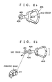
- FIG 3 is a outline perspective view of the tape actuator used in the embodiment of Figure 2.
- Figure 4 shows the cross section of Figure 3.
- Figure 5 shows the operating principle of the tape actuator, in which components identical with those of Figure 2 are give like reference numerals.
- This tape actuator is of a voice coil type which has no spring support and is similar in construction to a swing arm actuator or a tracking actuator used in the hard disk drive.
- reference numeral 11 represents a solenoid-driven tape actuator driving section to rotate the arm 12 attached with the movable tape pin 9 .
- Denoted 401 is a permanent magnet which is magnetized in the direction of extension of the rotating axis and whose magnetization on the right side is reverse to that on the left side.
- Designated 402 is a yoke made of soft magnetic material and 403 a movable coil that rotates about the rotating axis.
- the voice coil type solenoid-driven actuator has a magnetic circuit which is closed by the permanent magnet 401 and the yoke 402 , the permanent magnet 401 being magnetically divided in two areas with respect to the rotating plane of the movable coil 403, these areas being magnetized in two opposite directions perpendicular to the rotating plane of the movable coil 403 .
- This arrangement generates a high flux density in a direction perpendicular to the rotating plane of the movable coil 403 arranged parallel to the permanent magnet 401.
- the tape actuator of this construction has a "displacement angle/frequency" characteristic as shown in Figure 6.
- the ordinate represents gain and phase and the abscissa represents frequency.
- this actuator has no mechanical resonance up to high frequency and thus provides good controllability.
- it since it has no definite mechanical reference position, it is necessary to supply a signal that defines the reference position, as explained in Figure 2.
- Figure 7 shows an example of an optical sensor that measures the displacement of the arm 12 of the tape actuator 11 to determine the displacement (rotating angle) of the movable tape pin 9 .
- Designated 404 is a light emitting section, in which light generated by a laser diode 404a is collimated by a collimator lens 404b into a parallel-ray beam whose diameter is then restricted by a throttle.
- Denoted 405a is a reflecting section with a mirror surface, which is made by cutting the shaft 405 along the plane including the rotating axis 405' of the tape actuator 11; and 406 a light receiving section made up of a linear position sensor that detects the position of the light spot.
- the rotating axis 405 ' may be provided as an extension of the shaft 405 of Figure 4 or as a rotating axis supported by external bearings.
- the optical sensor 406 shown in Figure 7 is expensive though appropriate in cases where the rotating range of the tape actuator 11 is large. Where the rotating range is small, the light source may employ an LED which is less expensive than the laser diode or the linear position sensor may be replaced with a less expensive light receiving element which is divided in two to determine which of the divided two portions the light spot strikes.
- an inexpensive magnetic means can be used.
- a hall sensor 410 is provided to the rotating shaft 405 of the movable coil 403 in the voice coil type solenoid-driven actuator of Figures 3 to 5 so that it rotates with the shaft.
- a permanent magnet 411 with two oppositely magnetized regions is mounted to the base plate so that it faces the sensor 410. According to the output of the hall sensor 410 the rotating position of the tape actuator 11 can be detected.
- the paths through which the supply and takeup side movable tape pins 9a, 9b are driven by the tape actuators 11a , 11b are arcs rather than linear. This requires the DTF control system to absorb the non-linear errors for performing high-precision tracking.
- the DTF control according to the low-frequency component of the tracking error signal is mainly performed by the takeup side tape actuator 11b which has a wide movable range and a higher gain in the low-frequency region.
- the DTF control according to the high-frequency component of the tracking error signal-which is produced by the non-linearity of the moving path of the movable tape pin 9b - is carried out by the head actuator 14 that drives the magnetic head in a direction perpendicular to the recording track on the magnetic tape.
- the DTF control is performed in a two-step operation by the takeup side tape actuator and the head actuator and the dc component is dealt with by the capstan motor 6 or reel motor 5 .
- This realizes a stable, highly precise DTF control having a wide operation range.
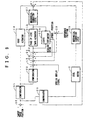
- Figure 9 is a block diagram showing the flow of physical quantities in the tracking control system of the embodiment of Figure 2.
- Figure 10 represents the block diagram of Figure 9 in terms of transfer functions of control logic. Referring to these figures, we will explain about the operation of the DTF control system of the invention.
- An element 25 is a compensator to make the head actuator 14 perform a stable tracking control.
- a band-pass filter 25a in the compensator 25 ( Figure 10) cuts the dc component of the tracking error signal and in the high-frequency range represents a first-order integration characteristic.
- An amplifier 25b, another component of the compensator 25 determines the control band of the tracking control system.
- An element 26 is a compensator to make the takeup side tape actuator 11b perform a stable tracking in cooperation with the head actuator 14 .
- a function 26a ( Figure 10), a part of the transfer function of the compensator 26, represents a transfer function of the secondary filter that electrically simulates the "displacement/voltage" frequency characteristic of the head actuator 14.
- Denoted 26b is a transfer function representing a gain of the amplifier.
- An element 28 is a compensator made up of a secondary low-pass filter.
- Denoted 28a ( Figure 10) is a transfer function representing the characteristic of the low-pass filter that passes only the low-frequency component of the tracking error.
- Denoted 28b is a transfer function representing a gain.
- An element 27 indicates a mechanical characteristic representing the displacement ratio between the longitudinal displacement of the magnetic tape and the displacement of the widthwise direction of the recording track.
- An element 29 is a mechanical characteristic representing the displacement ratio between the rotating angle of the reel motor 5 and the displacement in the widthwise direction of the recording track.
- the element 29 is a transfer function representing the ratio between the rotating angle of the reel motor 5 (or displacement angle of the takeup side tape actuator 11b ) and the magnetic tape displacement in the widthwise direction of the recording track.
- the element shown as the head actuator 14 in Figure 9 is a "drive voltage-displacement" characteristic of the head actuator 14.
- this is represented by a transfer function, where K H ⁇ is a torque constant, R H is a coil resistance, m H is a movable portion mass, C H is a viscosity coefficient, and R H is a modulus of elasticity.
- An element 11b in Figure 9 indicates a displacement angle (displacement/drive voltage) characteristic of the takeup side tape actuator 11b -which includes arm 12b and movable tape pin 9b (Figure 2)-when actually applied with a drive voltage.
- this characteristic is represented by transfer functions.
- Denoted 50 is a transfer function indicating the "torque/voltage" characteristic of the tape actuator; and 51 a transfer function representing the "displacement angle/torque" characteristic of the tape actuator where K T ⁇ is a torque constant, R T is a coil resistance, J T is an inertia of the rotating portion, and C T is a viscosity coefficient of the rotating portion.
- a subtractor 20 compares the estimated position from the state estimator 15b with the reference position of the takeup side tape actuator 11b to produce a position error signal. This comparison is taken for the following reason. Since the takeup side tape actuator 11b is not spring-supported, the application of the dc component to the capstan 6 and reel motor 5 of Figure 2 will leave the actuator position during the DTF operation undecided. Hence the position control system is formed to compare the reference position and the actual position of the takeup side tape actuator 11b , thereby electrically fixing the position of the actuator.
- An element 15b is a state estimator constructed of equal-dimension observer of modern control logic that electrically simulates the frequency characteristic and dynamic characteristic of the "displacement angle/drive voltage" of the takeup side tape actuator 11b . This will be detailed later.
- an element 32 is a transfer function representing a loop gain of the position control system for the takeup side tape actuator 11b .
- An element 33 is a transfer function representing a loop gain that forwardly feeds the estimated acceleration from the state estimator 15b.
- An element 34 is a transfer function representing a loop gain that feeds back the estimated speed from the state estimator 15b .
- Adder/subtractors 19 , 21, 22 1 , 22 2 are transfer functions representing addition and subtraction.
- An element 5 is a transfer function showing the characteristic of displacement angle with respect to the input voltage for the reel motor 5 or capstan motor 6 .
- K c ⁇ is a torque constant
- R c is a coil resistance
- J c is an inertial of the rotating portion.
- An adder 31 determines the actuator position in the longitudinal direction of the magnetic tape according the signals from the head actuator 14, takeup side tape actuator 11b and reel motor 5 (or capstan motor 6 ).
- a subtractor 30 shows conceptually the subtracting operation to take a difference between the target track position corresponding to the track position on the magnetic tape to be traced and the tracking position fed from the adder 31 .
- the output of the subtractor 30 can be used as a tracking error signal.
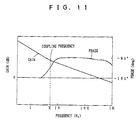
- the DTF control based on the low-frequency component of the tracking error signal is carried out by the takeup side tape actuator 11b and the DTF control based on the high-frequency component, produced by the non-linearity of the path of the movable tape pin 9b, is performed by the head actuator 14, it is desired that the coupling frequency-a frequency where the gains of the control loops for the takeup side tape actuator 11b and head actuator 14 are equal-be set close to the cycle frequency F s of, for example, 7.5Hz.
- the fundamental frequency of the tracking error signal containing the non-linear error is the cycle frequency F s , i.e., the drive pattern signal of the tape actuator 11.
- the coupling frequency is set close to the cycle frequency F s , it is possible to form a two-step coupling system in which the high-frequency component of the tracking error signal is given mainly to the head actuator 14 which has a good follow-up capability for high-frequency signal and in which the low-frequency component is given mainly to the tape actuator 11 which has a large low-frequency torque and a good low-frequency follow-up capability.
- this embodiment employs the state estimator 15b , formed by the equal-dimension observer of modern control logic, to estimate the speed of the actuator 11 and feeds it back through a high gain 34, thereby transforming the low-frequency characteristic of the "displacement/voltage" frequency characteristic into a stable first-order form to stabilize the whole system.
- the estimated external disturbance torque calculated by the state estimator 15b is fed forward in order to assure stable operation at all times regardless of the tape tension.
- the state estimator 15b simulates the transfer function and dynamic characteristic of the takeup side tape actuator 11b as an equivalent electric circuit. It can estimate the acceleration, velocity, position and external disturbance of the takeup side tape actuator 11b with high precision and in wide frequency range.
- the state estimator 15a ( Figure 2) to control the supply side tape actuator 11a for the tension control described later also has a construction similar to that of the state estimator 15b.
- denoted 100 is a transfer function that electrically simulates the transfer function 50 which represents the actual "torque/drive voltage" of the takeup side tape actuator 11b .
- Designated 101 is a transfer function that electrically simulates the transfer function 51 -which represents the actual "torque/drive voltage” characteristic of the takeup side tape actuator 11b -through the equivalent conversion of control logic and in cooperation with the transfer function 103.
- Elements 105, 106 are feedback gain transfer functions of the observer that converge to zero the difference between the reference position signal from the position sensor 13b ( Figure 2) corresponding to the output d of the takeup side tape actuator 11b and the output of the transfer functions 100, 101, 103, in order that the dynamic characteristic produced by the transfer functions 100, 101, 103, which electrically simulate the characteristic of the tape actuator 11b , will match the actual characteristic of the tape actuator 11b .
- Denoted 102, 104, 107 are subtractors.
- the transfer functions 101, 103 electrically simulate the mechanical characteristic transfer function 51 of the takeup side tape actuator 11b . Supplying the output b' of the transfer function 100 to the element 101 will produce an output d' of the element 103 that represents the estimated rotating angle d of the takeup side tape actuator 11b.
- the transfer functions 101, 103 have their own internal integrators, so that even when they provide the same characteristic as that of the transfer function 51 of the takeup side tape actuator 11b in terms of frequency characteristic, their dynamic characteristic will not be equal to that of the transfer function 51 because of the difference in the initial values of the integrators.
- the difference e between the actual displacement d of the takeup side tape actuator 11b detected by the position sensor not shown and the estimated value d' given by the state estimator 15b is fed back through the gain F 1 and F 2 so that not only the frequency characteristic but the dynamic characteristic will match the rotation of the real tape actuator.
- the configuration of the state estimator 15b mentioned above is well known as the configuration of the equal-dimension observer of the modern control logic.
- the reason that the two feedback loops including gains F 1 , F 2 are connected to the front of the transfer functions 101, 103 including integrators (1/ S in Laplace transform) in the state estimator 15b , an electrical model of the takeup side tape actuator 11b, is to allow the convergence of the observer to be determined freely.
- the equal-dimension observer that receives the drive voltage and displacement of an object to be controlled is used to produce an estimated speed of the object.
- the dynamic characteristic and the static characteristic (frequency characteristic) set equal to those of the controlled object, if the observer feedback gains F 1 , F 2 are increased to make the observer pole sufficiently large (a negative real number increases) compared with the pole of the controlled object, the observer can estimate the tension. Since the dynamic characteristic of the observer agrees with that of the controlled object, the following relationship holds between the estimated displacement d' and the actual displacement d . d ' ⁇ d
- the signal path a' in the observer represents the external disturbance torque due to tension and, by picking up this signal, it is possible to detect the external disturbance torque.
- the use of the state estimator 15 permits detection of the position, velocity, acceleration, and external disturbance of the tape actuator 11 with high precision and in wide frequency range.
- the tracking error signal output from the subtractor 30 shown at the upper left in Figure 10 can be obtained from the envelope of the signal reproduced by the magnetic head, by means of the aforementioned known method such as a pilot method.
- This tracking error signal is supplied to the compensator 28 where it passes through the low-pass filter 28a with cut-off frequency of several Hz and is then amplified by the amplifier 28b, which has the gain set equal to a gain of the third control loop at the frequency of several Hz. Then, the amplified tracking error signal is fed to a drive amplifier not shown to drive the reel motor 5 or capstan motor 6 according to the speed of the tape. The tracking error signal is further fed to the mechanical characteristic 29, which is determined by the reel diameter and track inclination angle, to move the magnetic tape in the longitudinal direction thereby compensating for the low-frequency error containing the dc component of the tracking error.
- the first control loop works to eliminate the tracking error according to the tracking error signal.
- This control loop forms a closed loop.
- the tracking error signal is also supplied to the compensator 25 where it is phase-compensated by the band-pass filter 25a made up of first-order high-pass filter and low-pass filter, whose center frequency is several tenths of Hz, and then is amplified by the amplifier 25b to a specified gain.
- the amplified tracking error signal is further supplied to a drive amplifier not shown to drive the head actuator 14 to move the magnetic head H in the track width direction.
- the second control loop also forms a closed loop as in the case of the first control loop.
- the output of the amplifier 25b in the compensator 25 is fed to a compensator 26a , which is formed of a phase advance filter that places all the poles of the control system on the left side surface.
- the signal is amplified by an amplifier 26b so that the gain of the third loop is equal to that of the second loop at a certain frequency.
- the amplified signal is further fed through a special replay signal adder 19 , a speed damping signal subtractor 22 and an external disturbance elimination signal adder 21 to a drive amplifier not shown to drive the takeup side tape actuator 11b to move, via the mechanical characteristic 27 , the magnetic tape T in the longitudinal direction, thus compensating for the tracking error.
- this third control loop is also closed as with the first and second control loops.
- This embodiment realizes a DTF control having a high precision and wide frequency and dynamic ranges by using three electrically coupled DTF control loops.
- the open loop characteristic is shown in Figure 11.
- the drive voltage for the takeup side tape actuator 11b is added to the reference position signal of the position control loop to differentially operate the two tape actuators 11a, 11b in any operation mode, such as normal replay mode and high-speed special replay mode, to prevent tension variations at the rotary head.
- this embodiment employs a closed loop tension control which compensates for tension variations and thereby maintains an optimum tension during any operation mode.
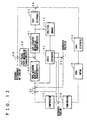
- Figure 12 is a block diagram of the tension control system mentioned above.
- Figure 13 represents the tension control system in terms of transfer functions of control logic. Elements in Figures 12 and 13 that are identical with those of Figure 2 are assigned like reference numerals. S in Figure 13 represents a Laplacean.
- an element 50 represents an electric characteristic or "generated torque/input voltage" frequency characteristic of the supply side tape actuator 11 .
- An element 51 is a mechanical characteristic or “displacement angle/supply torque” characteristic of the supply side tape actuator 11a . This is the same characteristic as that of the takeup side tape actuator 11b.
- An element 52 indicates a tape stiffness or "stress/strain" characteristic of the tape in the longitudinal direction.
- An element 53 is a tape path mechanical characteristic, which is determined by the geometrical positional relationship between the stationary tape pin 10a and the supply side movable tape pin 9a , the balance of force between the magnetic tape T and the supply side movable tape pin 9a, and the geometrical positional relationship between the movable tape pin 9a and the rotating shaft of the supply side tape actuator 11a .
- An element 15a is a state estimator which electrically estimates the acceleration and speed of the tape from the drive voltage or drive current for the supply side tape actuator 11a and the detected displacement given by the position sensor 13a.
- Elements 55, 56 are compensators which feed back to the supply side tape actuator 11a and the supply reel motor 4 a difference between the estimated tension from the tension estimator 15a and the reference tension, i.e., an external disturbance-induced tension, in order to stabilize the loop.
- a tape stiffness 52 indicates the tape stiffness that represents tape tension variation characteristic caused by changes in the rotating angle of the reel motor 4 .
- a subtractor 54 takes a difference between the estimated tension from the state estimator 15a and the reference tension.
- Adders 57, 58 and a subtractor 59 represent a balance of physical forces or torque.
- An adder/subtractor 24 adds and subtracts the estimated speed given by the state estimator 15a and the position error to and from the acceleration control loop.
- the magnetic tape tension change detected based on the rotating angle change of the supply side tape actuator 11a is added to the tension change due to the reel motor rotating angle change.
- This sum of tension changes is added with the tension disturbance (such as dynamic frictions on the tape receiving shaft and head cylinder, tape friction coefficient variations, external disturbing force in the tape longitudinal direction, etc.) to produce a total sum of the tensions in the magnetic tape path, which is used to control the supply side tape actuator 11a .
- a signal TG indicates a external tension disturbance and an element 11a is a transfer function representing the actual "displacement angle/input voltage" characteristic of the supply side tape actuator 11a, which is the same as that of the takeup side tape actuator 11b of Figure 10.
- An element 52 is a transfer function indicating the transfer characteristic of the tape tension variations in relation to the rotating angle change of the supply side tape actuator 11a .
- An element 53 is a transfer function showing the transfer characteristic of the torque that the tape tension applies to the supply side tape actuator 11a .
- An element 15a is a state estimator having the same configuration as the state estimator 15b described in connection with the DTF control system of Figure 10. This state estimator estimates the position, velocity, acceleration, and external torque of the tape actuator 11a .
- An element 108 is a transfer function that represents an inverted characteristic of the transfer function 53, the transfer function 53 expressing the transfer characteristic of the torque that the tape tension imparts to the supply side tape actuator 11a.
- An element 55a is a transfer function of a band-pass filter, which is a part of the compensator 55, to feed back to the supply side tape actuator 11a a relatively high frequency component in the control band in the tension control system.
- An element 55b is an amplifier gain transfer function that determines the loop gain of the feedback loop for the supply side tape actuator 11a.
- An element 56a is a secondary low-pass filter transfer function, a part of the compensator circuit 56 , to feed back to the supply reel motor 4 a relatively low frequency component in the control band in the tension control system.
- An element 56b is an amplifier gain transfer function that determines the loop gain of the feedback loop for the reel motor 4.
- An element 4 is a transfer function including the coil resistance R L , torque constant K L ⁇ and rotating portion inertia J L of the reel motor 4.
- An adder/subtractor 23 is a computation element that compares the estimated position signal from the state estimator 15a and the reference position signal and also adds the drive voltage of the takeup side tape actuator 11b .
- An element 61 is a loop gain transfer function that feeds back the position error signal from the computation element 23.
- An element 60 is a gain transfer function of the loop that feeds back the estimated speed from the state estimator 15a .
- An adder/subtractor 24 is a computation element that adds and subtracts the position control loop signal and the speed control loop signal to and from the tension control loop.
- the displacement of the spring-supported tension control arm 77 is proportional to the tension only when the tension variation frequency of the arm 77 is lower than the spring resonance frequency.
- the tension variation frequency exceeds the spring resonance frequency
- the tension variation applied to the tension control arm 77 deviates in phase from the position variation of the arm 77 .
- the phase deviates 90 degrees.
- the phase shift amounts to 180 degrees.
- the conventional tension control has the control frequency band limited by the phase of the spring-supported system including the tension control arm 77 . This means that the tension that can be detected by the tension control arm 77 is less than the spring resonance frequency of the spring-supported system including the tension control arm 77 .
- a means to raise the spring resonance frequency may include reducing the weight of the tension control arm or increasing the spring constant.
- reducing the weight of the tension control arm has its limitation and the increasing of the spring constant makes the tension control arm 12 more dull in responding to the tension variation, deteriorating the detection accuracy.
- this embodiment employs an actuator that has no spring support as explained in Figure 3 to 5.
- the subtractor 23 shown at the upper left in Figure 2 and the subtractor 20 at the right are given voltages that determine the reference positions of the supply and takeup side tape actuators 11a , 11b , thereby performing an electric position control, rather than mechanical control, of the tape tension control arm 77 .
- the actuator is electrically spring-supported.
- This construction permits a wide range detection of tension irrespective of the position control range.
- the external disturbance torque signal from the state estimator 15a is the tape tension applied to the supply side tape pin 9a coupled to the supply side tape actuator 11a and thus can be treated as the tension signal.
- the tension aa' estimated as described above is compared by the comparator 54 with the reference tension TN, which is the optimum value of the tension, to produce a tension error signal TG.
- the tension error signal TG is phase-compensated by a compensator 55a , which consists of a first-order band-pass filter with the cut-off frequency of several Hz, sufficiently lower than the control frequency band.
- the tension error signal is then amplified by an amplifier 55b with a certain gain and supplied through the tape actuator position control signal adder and the speed damping signal subtractor 24 to a drive amplifier not shown to drive the supply side tape actuator 11a .
- the tension error signal TG is also fed to a compensator 56a made up of a second-order low-pass filter where it is amplified by an amplifier 56b so that it is stably coupled to the first control loop at several Hz.
- the tension error signal is further fed to a drive amplifier not shown to drive the reel motor 4 to keep the tension constant. In this way, the second control loop is also closed.
- the frequency range is divided as described above because the supply side tape actuator 11a generally has a small mechanical time constant when compared with the reel motor 4 and is thus suited for a control in a high frequency range while at the same time it has a limited control amount and is not suited for a control of large tension variations near dc.
- the estimated speed from the state estimator 15a is amplified by an amplifier 60 and fed back with high gain to the supply side tape actuator 11a , as previously explained in connection with the DTF control.
- the gain of the amplifier 60 is so set that the frequency band in which the characteristic is transformed into the stable first-order form is approximately equal to or higher than the tension control range.
- the position signal from the state estimator 15a or the position signal from the position sensor 13a is compared with the reference position signal by the subtractor 23 to produce a position error signal, which is then amplified by an amplifier 61 with a gain G 8 and fed back to the supply side tape actuator 11a .
- the feedback loop gain G 8 should preferably be set so that the normal deviation of the position control loop for the supply side tape actuator 11a from the tape tension reference value TN is several tens to several hundred ⁇ m.
- the reason that the position control loop does not perform the phase compensation is that the characteristic of the supply side tape actuator 11a is improved into the stable first-order form by the speed damping loop.
- the tension control by using the above-mentioned tension disturbance estimation method enables a wider range and higher precision detection of the estimated magnetic tape tension than can be detected by the conventional tension detection mechanism.
- the tension control system since the high-frequency component of the tension variation is suppressed by the supply side tape actuator 11a and the low-frequency component by the reel motor, the tension control system has an improved tension control precision and a wider frequency range and dynamic range.
- the DTF control and tension control having high precision, wide frequency range and wide dynamic range are realized, permitting a good replay not only during the normal speed replay but also during the high-speed special replay mode.
- the first embodiment of Figure 14 to Figure 16 has a head touch control circuit 200 to keep the gap or spacing between the magnetic head and the magnetic tape constant; and an adder 201 to add a head touch control signal from the head touch control circuit 200 to an estimated acceleration signal from the state estimator 15a in the tension control loop.
- This first embodiment does not include a head actuator and associated means for moving the magnetic head perpendicular to the track for correct tracking in order to make the system less expensive or reduce the size of the head cylinder.
- the tension control circuit shown in the embodiment of Figures 2 to 13 can keep at an optimum tension with high precision in wide range the tension of the magnetic tape T at the supply side movable tape pin 9a . From the perspective of the head touch control, however, it is the tension of the tape at the magnetic head H that actually needs to be tension-controlled.
- Figure 14 is a block diagramm showing the concept of the first embodiment.
- Figure 15 shows the flow of physical Quantities in the DTF control system.
- Figure 16 represents the DFT control system of Figure 16 in terms of transfer functions of control logic.
- Figure 18 is a block diagram showing the head touch control circuit.
- the DTF control system of this embodiment shown in Figures 15 and 16 is compared with the DTF control system of the embodiment shown in Figures 9 and 10.
- This embodiment does not have a head actuator and therefore the element 14, which is shown in Figure 10 and represents the head actuator transfer function.
- This embodiment controls the capstan motor 6 instead of the reel motor of the winding reel 5 as shown by element 5 in Figure 9.
- the DTF control system of this embodiment performes the high-frequency component control by the takeup side tape actuator 11b and the low-frequency component control by the capstan motor 6 .
- the first embodiment also has a state estimator 15b and performs the speed feedback to transform the low-frequency characteristic of the takeup side tape actuator 11b into a stable first-order form.
- the position control and the external disturbance elimination control are also performed in a way similar to the embodiment of Figures 2 to 13.
- a tracking error signal (the output of the subtractor 30 ) produced by the pilot method from the replay envelope signal of the magnetic head H is supplied to a compensator 28 where it passes through a low-pass filter 28a with cut-off frequency of several Hz and is then amplified by an amplifier 28b, which has the gain so set that the amplified signal couples with the second control loop for the takeup side tape actuator 11b in the frequency range of several Hz to 10 Hz.
- the signal is further fed to a drive amplifier not shown to drive the capstan motor 6 during normal operation as shown and, during high-speed replay, drive the reel motor 5 .
- the low-pass filter 28a need not necessarily be used.
- the capstan motor 6 or (reel motor 5 ) moves, via the mechanical characteristic, the magnetic tape T in its longitudinal direction to correct the low-frequency error containing dc component of the tracking error signal.
- the first control loop is closed through the tracking error.
- the tracking error signal is also supplied to a compensator 25 where it is passed through a high-pass filter 25a , whose cut-off frequency is several tenths of Hz, which is lower than the cut-off frequency of the low-pass filter 28a of the compensator 28.
- the tracking error signal is then amplified by an amplifier 25b to a desired amplitude and further sent to a special replay signal adder 19 , speed damping signal subtractor 22 1 , external disturbance elimination signal adder 21 , and position control signal adder 22 2 to a drive amplifier not shown to drive the takeup side tape actuator 11b.
- the takeup side tape-actuator 11b moves, via the mechanical characteristic, the magnetic tape T in its longitudinal direction to correct the tracking error. Hence, the second control loop is also closed through the tracking error.
- these two electrically coupled DTF control loops combine to realize a DTF control that has high precision, wide frequency range and wide dynamic range.
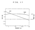
- An example open loop characteristic of the DTF control is shown in Figure 17.
- Characteristic of the DTF control system of this embodiment is the fact that the low-frequency characteristic of the takeup side tape actuator 11b is transformed into a stable first-order form by the speed feedback up to a frequency higher than the DTF control frequency range. This enables easy coupling with the capstan motor 6 , which is of the second-order form, and also allows a stable DTF control.
- Figure 18 is a block diagram showing one example configuration of a head touch control circuit 200.
- Denoted 202 is a detecting circuit; 203 a peak hold circuit; 204 a subtractor; 205 a limiter; 206 an absolute value circuit; 207 a level identifier; and 208 an analog switch. Signals at points a to d in the figure are shown in Figure 19.
- the reproduced signal a from the magnetic head is detected by a detector 202 to obtain an envelope signal b , whose peak value is held by a peak hold circuit 203 that produces a peak level signal c .
- the peak hold circuit 203 may use an analog-voltage memory. Unless the recording condition changes, the peak value does not change in practice and therefore the peak value need only be updated by resetting the peak hold circuit every several turns of the head cylinder D . In the figure, the peak value c is shown as an almost constant voltage.
- a signal d is obtained at the fixed contact of a switch 208.
- the switch is operated by a rotary head phase signal-which represents the rotating phase of the magnetic head and has a 50% duty ratio-to produce a spacing error signal e .
- the spacing error signal e represents the amount by which the envelope signal falls, and it is necessary to identify whether the fall is due to track shift or spacing error.
- the track shift should be almost zero or at a negligible level. But for the purpose of safety the following steps are taken.
- the absolute value is taken of the tracking error signal by the absolute value circuit 206 and, when its output level exceeds a specified value equivalent to 10% of the track pitch, the level identifier 207 opens the switch 209 to cut off the control loop of the head touch control circuit.
- the limiter 205 restricts the output amplitude of the spacing error signal e from the head touch control circuit below a specified level because too large a spacing error signal e will cause a sharp change in the tape tension and therefore damage to the tape.
- the spacing error signal e output from the limiter 205 is added by the adder 201 to the estimated tension signal produced by the state estimator 15a of the DTF control system.
- FIG. 18 Shown by one-dot line in Figure 18 is a variation of the head touch control circuit, which subtracts the tracking error signal f from the spacing error signal e -which represents the amount of fall of the envelop signal-to derive a pure spacing error signal g .
- Figure 20 shows example signals at point e, f, g.
- This head touch control method is effective for applications that do not use the DTF control.
- the tension control system is also possible to perform an open-loop control as by storing the error patterns of the spacing error signal g in memory. In this case, a better result can be obtained if a gain to be added is selected according to the error pattern of the spacing error signal.
- simple and inexpensive DTF control, tension control and head touch control can be realized, keeping the tape in an optimum tension at all times and assuring a good signal reproduction.
- the second embodiment shown in Figure 21 is the embodiment of Figures 2 to 13 added with the head touch control of the first embodiment. Its operation and effect are already described in the above embodiments and thus not given here.
- the tension control and DTF control of the magnetic tape is performed in a wide dynamic range and a wide frequency band with high precision. Provision of the control system using the state estimator and the surface pressure estimator enhances the control performance of the recording and reproducing apparatus, so that a good reproduction can be obtained not only during normal speed replay but also during special replays at other speeds than the normal speed without generating noise on the picture. Further, the system becomes less expensive.
- the control to keep constant the surface pressure that the magnetic head receives from the magnetic recording medium allows the spacing between the magnetic head and the recording medium to be maintained at a constant value in a wide frequency range with high precision and good response. This in turn permits the line recording density to be increased. During high-density recording, since there is no contact between the magnetic tape and the magnetic head, wear of these components can be reduced.
Landscapes
- Engineering & Computer Science (AREA)
- Signal Processing (AREA)
- Adjustment Of The Magnetic Head Position Track Following On Tapes (AREA)
Claims (5)
- Magnetisches Aufzeichnungs- und Wiedergabegerät, welches aufweist:gekennzeichnet durcheine Abwickelspulen-Antriebsvorrichtung (4) zum Antreiben einer Abwickelspule, auf welche ein Magnetband (T) gewickelt ist;eine Magnetband-Zuführungsvorrichtung zum Antreiben des Magnetbandes mit einer bestimmten Geschwindigkeit von der Abwickelspule zu einem Kopfzylinder (D), auf welchem ein drehbarer Magnetkopf (Ha, Hb) befestigt ist;einen zuführungsseitigen bewegbaren Stift (9a), der sich in dem Weg des Magnetbandes im Bereich von der Abwickelspule bis zum Kopfzylinder (D) befindet und so ausgebildet ist, daß er die Länge des Bandweges zwischen der Abwickelspule und dem Kopfzylinder (D) verändert;ein zuführungsseitiges Bandbetätigungsglied (11a) zum Antreiben des bewegbaren Stiftes (9a) ;eine Positionserfassungsvorrichtung (13a) zum Erfassen der Position des bewegbaren Stiftes (9a) ;eine Spannungserfassungsvorrichtung (15a) zum Berechnen der Spannung des Magnetbandes (T) aus einem Ausgangssignal der Positionserfassungsvorrichtung (13a) und der Antriebsspannung oder dem Antriebsstrom für das zuführungsseitige Bandbetätigungsglied (11a) ;eine Spannungssteuervorrichtung (17) zum Ausgeben eines Spannungssteuersignals für die Steuerung der Spannung des Magnetbandes (T) auf einen bestimmten Wert durch Betätigen der Abwickelspulen-Antriebsvorrichtung (4) allein oder in Verbindung mit dem zuführungsseitigen Bandbetätigungsglied (11a) entsprechend dem Ausgangssignal der Spannungserfassungsvorrichtung (15a);eine Abstandserfassungsvorrichtung (200) zum Erfassen eines Abstandsfehlers zwischen dem drehbaren Magnetkopf (Ha, Hb) und dem Magnetband (T) auf der Grundlage einer Umhüllung eines Signals, das durch den Magnetkopf (Ha, Hb) von dem Magnetband (T) wiedergegeben ist, und zum Erzeugen eines Abstandsfehlersignals, das den erfaßten Abstandsfehler anzeigt, undeine Vorrichtung (201) zum Addieren des von der Abstandserfassungsvorrichtung (200) erzeugten Abstandsfehlersignals zu dem Spannungssteuersignal.
- Magnetisches Aufzeichnungs- und Wiedergabegerät nach Anspruch 1, worin die Abstandserfassungsvorrichtung (200) das Abstandsfehlersignal über eine Begrenzerschaltung (205) ausgibt, so daß das Abstandsfehlersignal einen bestimmten Pegel nicht übersteigt.
- Magnetisches Aufzeichnungs- und Wiedergabegerät nach Anspruch 1 oder 2, gekennzeichnet durch eine Vorrichtung (202) zum Erfassen der Umhüllung eines durch den Magnetkopf (Ha, Hb) von dem Magnetband (T) wiedergegebenen Signals;eine Vorrichtung (16) zum Erzeugen eines Spurfehlersignals entsprechend dem durch den Magnetkopf (Ha, Hb) von dem Magnetband (T) wiedergegebenen Signal, welches eine relative Positionsdifferenz oder einen Fehler zwischen dem Magnetkopf (Ha, Hb) und der Aufzeichnungsspur auf dem Magnetband (T) darstellt; undeine Vorrichtung zum Erfassen des Abstands gemäß einer Differenz zwischen dem Ausgangssignal der Umhüllungserfassungsvorrichtung und dem Spurfehlersignal.
- Magnetisches Aufzeichnungs- und Wiedergabegerät nach Anspruch 3, dadurch gekennzeichnet, daß die Abstandserfassungsvorrichtung (200) eine Entscheidungsvorrichtung (207) aufweist, um aus dem Spurfehlersignal zu erfassen, ob der Spurfehler klein ist, und in diesem Fall eine Schaltervorrichtung (209) zu schließen, um das Abstandsfehlersignal auszugeben.
- Magnetisches Aufzeichnungs- und Wiedergabegerät nach Anspruch 4, dadurch gekennzeichnet, daß die Entscheidungsvorrichtung (207) den Pegel des Spurfehlersignals prüft durch Vergleich der Amplitude des Spurfehlers mit einer vorbestimmten Spannung.
Applications Claiming Priority (6)
| Application Number | Priority Date | Filing Date | Title |
|---|---|---|---|
| JP10758191 | 1991-05-13 | ||
| JP10758191 | 1991-05-13 | ||
| JP107581/91 | 1991-05-13 | ||
| JP120514/91 | 1991-05-24 | ||
| JP12051491 | 1991-05-24 | ||
| JP12051491 | 1991-05-24 |
Publications (3)
| Publication Number | Publication Date |
|---|---|
| EP0513744A2 EP0513744A2 (de) | 1992-11-19 |
| EP0513744A3 EP0513744A3 (en) | 1994-06-08 |
| EP0513744B1 true EP0513744B1 (de) | 1999-08-04 |
Family
ID=26447604
Family Applications (1)
| Application Number | Title | Priority Date | Filing Date |
|---|---|---|---|
| EP92108009A Expired - Lifetime EP0513744B1 (de) | 1991-05-13 | 1992-05-12 | Magnetisches Aufzeichnungs- und Wiedergabegerät |
Country Status (4)
| Country | Link |
|---|---|
| US (3) | US5395066A (de) |
| EP (1) | EP0513744B1 (de) |
| DE (1) | DE69229690T2 (de) |
| SG (1) | SG65558A1 (de) |
Families Citing this family (29)
| Publication number | Priority date | Publication date | Assignee | Title |
|---|---|---|---|---|
| KR970005641B1 (ko) | 1993-04-16 | 1997-04-18 | 구자홍 | 디지탈 브이씨알의 기록 및 재생제어회로 |
| JPH07298667A (ja) * | 1994-04-28 | 1995-11-10 | Matsushita Electric Ind Co Ltd | モータ制御装置 |
| JP2776289B2 (ja) * | 1995-03-14 | 1998-07-16 | 松下電器産業株式会社 | 回転ヘッド高さ測定装置及び方法 |
| WO1996038840A2 (en) * | 1995-06-01 | 1996-12-05 | Philips Electronics N.V. | Magnetic recording apparatus |
| KR0185951B1 (ko) * | 1995-07-04 | 1999-05-15 | 김광호 | 회전모터의 속도제어방법 및 그 장치 |
| US5773938A (en) * | 1995-07-04 | 1998-06-30 | Samsung Electronics Co., Ltd. | Apparatus for controlling speed of a rotary motor |
| KR0178749B1 (ko) * | 1996-01-30 | 1999-04-15 | 김광호 | 자기기록/재생장치의 엔벨로프 검출회로 |
| JP3058131B2 (ja) * | 1997-08-23 | 2000-07-04 | 日本ビクター株式会社 | 磁気記録再生装置 |
| KR19990061744A (ko) * | 1997-12-31 | 1999-07-26 | 윤종용 | 하드 디스크 드라이브 헤드의 파킹 방법 |
| JP3794155B2 (ja) * | 1998-03-12 | 2006-07-05 | ソニー株式会社 | 磁気記録再生装置及び磁気記録再生方法 |
| US6466384B1 (en) | 2000-01-04 | 2002-10-15 | International Business Machines Corporation | Apparatus and method for reading magnetic images with an adjustable force pressure pad |
| US6563659B1 (en) | 2000-03-08 | 2003-05-13 | Hewlett-Packard Development Company, L.P. | Method and apparatus for servo code based tape tension measurement |
| US6950274B2 (en) * | 2001-11-28 | 2005-09-27 | Matsushita Electric Industrial Co., Ltd. | Disk storage apparatus and disk storage apparatus control method |
| US6934108B2 (en) * | 2003-01-22 | 2005-08-23 | International Business Machines Corporation | Servo pattern based tape tension control for tape drives |
| JP3918762B2 (ja) * | 2003-04-04 | 2007-05-23 | ソニー株式会社 | 記録信号再生装置および記録信号再生方法 |
| US6935590B2 (en) * | 2003-05-19 | 2005-08-30 | Autoliv Asp, Inc. | Sensor for a feedback control system |
| US7140571B2 (en) | 2003-06-11 | 2006-11-28 | Autoliv, Asp, Inc. | Electric seat belt retractor system |
| US7016138B2 (en) * | 2003-09-12 | 2006-03-21 | Quantum Corporation | Tension feedback system for a tape drive |
| JP4268108B2 (ja) * | 2004-09-13 | 2009-05-27 | 富士通株式会社 | 磁気記録再生装置および磁気記録再生方法 |
| JP2007034149A (ja) * | 2005-07-29 | 2007-02-08 | Fujifilm Holdings Corp | 回転検出方法及び装置、及び写真フイルムパトローネのフイルム係止検出方法及び装置 |
| US7486464B2 (en) * | 2005-10-20 | 2009-02-03 | Quantum Corporation | Ultra high track density adaptive head core track pitch control |
| US7600709B2 (en) * | 2007-04-05 | 2009-10-13 | Quantum Corporation | Tape tension sensor |
| US9159347B1 (en) * | 2014-06-17 | 2015-10-13 | International Business Machines Corporation | Usage of state information from state-space based track-follow controller |
| US9230590B1 (en) | 2014-12-11 | 2016-01-05 | International Business Machines Corporation | Dynamic adjustments of tape head wrap angles |
| US9548077B1 (en) | 2015-12-07 | 2017-01-17 | International Business Machines Corporation | Detecting and compensating for external vibration in a tape drive |
| CN108873698B (zh) * | 2018-07-07 | 2021-06-01 | 福州大学 | 一种抗扰动两阶段定点伺服控制方法 |
| US11087786B1 (en) | 2020-04-30 | 2021-08-10 | Western Digital Technologies, Inc. | Tape drive with head-gimbal assembly and contact plate |
| CN113267995B (zh) * | 2021-04-27 | 2022-08-26 | 长春同泽科技有限公司 | 一种驱动控制装置、控制方法及矿井运输车 |
| US11735223B2 (en) * | 2021-06-29 | 2023-08-22 | Western Digital Technologies, Inc. | Head suspension system for a tape drive |
Family Cites Families (15)
| Publication number | Priority date | Publication date | Assignee | Title |
|---|---|---|---|---|
| JPS59229761A (ja) * | 1983-06-09 | 1984-12-24 | Trio Kenwood Corp | 磁気テ−プ機器用張力制御装置 |
| JPS62184652A (ja) * | 1986-02-07 | 1987-08-13 | Sony Corp | 記録再生装置 |
| US4739948A (en) * | 1986-04-11 | 1988-04-26 | Ampex Corporation | Reel servo control with resonance damping circuit |
| JPH0679400B2 (ja) * | 1987-05-29 | 1994-10-05 | 松下電器産業株式会社 | 磁気記録再生装置 |
| JPH01311481A (ja) * | 1987-10-29 | 1989-12-15 | Sony Corp | 磁気ヘッド装置 |
| US5032936A (en) * | 1988-06-27 | 1991-07-16 | Matsusita Electric Industrial Co. Ltd. | Tape tension apparatus |
| JPH0823950B2 (ja) * | 1988-06-27 | 1996-03-06 | 松下電器産業株式会社 | テープ走行装置 |
| JPH0675321B2 (ja) * | 1988-09-14 | 1994-09-21 | 松下電器産業株式会社 | テープ走行装置 |
| JPH0278045A (ja) * | 1988-09-14 | 1990-03-19 | Matsushita Electric Ind Co Ltd | テープ走行装置 |
| US5153785A (en) * | 1988-09-19 | 1992-10-06 | Hitachi, Ltd. | Apparatus for measuring the clearance of recording transducer, and a recorder using the apparatus, and a method of controlling the recorder |
| JPH02246011A (ja) * | 1989-03-17 | 1990-10-01 | Matsushita Electric Ind Co Ltd | 回転磁気ヘッド接触力測定装置 |
| JPH0346114A (ja) * | 1989-07-13 | 1991-02-27 | Canon Inc | 磁気記録再生装置 |
| JP2738088B2 (ja) * | 1989-11-27 | 1998-04-08 | 松下電器産業株式会社 | テープ走行装置 |
| JP2694047B2 (ja) * | 1989-12-06 | 1997-12-24 | 三菱電機株式会社 | 磁気記録再生装置 |
| JPH0495211A (ja) * | 1990-08-08 | 1992-03-27 | Matsushita Electric Ind Co Ltd | 回転ヘッド装置 |
-
1992
- 1992-05-12 EP EP92108009A patent/EP0513744B1/de not_active Expired - Lifetime
- 1992-05-12 SG SG1996002770A patent/SG65558A1/en unknown
- 1992-05-12 DE DE69229690T patent/DE69229690T2/de not_active Expired - Fee Related
- 1992-05-13 US US07/882,016 patent/US5395066A/en not_active Expired - Fee Related
-
1994
- 1994-05-26 US US08/249,745 patent/US5481417A/en not_active Expired - Fee Related
-
1995
- 1995-09-11 US US08/526,176 patent/US5602688A/en not_active Expired - Fee Related
Also Published As
| Publication number | Publication date |
|---|---|
| SG65558A1 (en) | 1999-06-22 |
| US5602688A (en) | 1997-02-11 |
| US5481417A (en) | 1996-01-02 |
| US5395066A (en) | 1995-03-07 |
| DE69229690T2 (de) | 1999-12-02 |
| DE69229690D1 (de) | 1999-09-09 |
| EP0513744A2 (de) | 1992-11-19 |
| EP0513744A3 (en) | 1994-06-08 |
Similar Documents
| Publication | Publication Date | Title |
|---|---|---|
| US5481417A (en) | Tape tension control for a magnetic recording and reproducing apparatus that adjusts spacing error based on the reproduced signal envelope | |
| US5566378A (en) | Movable head position controlling device for magnetic recording and reproducing apparatuses | |
| EP0509545B1 (de) | Positioniervorrichtung für einen Magnetkopf in einem magnetischen Aufnahme- und Wiedergabegerät | |
| JPS5853419B2 (ja) | ウエブユソウソウチ | |
| EP0570956B1 (de) | Magnetisches Aufzeichnungs-/Wiedergabegerät | |
| US5725168A (en) | Magnetic recording and reproducing apparatus for controlling the tension of a magnetic tape | |
| JPH0346114A (ja) | 磁気記録再生装置 | |
| KR930003248B1 (ko) | 자기기록 재생장치의 트래킹 장치 | |
| JP3063384B2 (ja) | 磁気記録再生装置 | |
| JP2600558B2 (ja) | 磁気記録再生装置における磁気ヘッド位置制御装置 | |
| JP2637609B2 (ja) | 磁気再生装置におけるトラッキング制御システム | |
| JP2726810B2 (ja) | 磁気再生装置 | |
| JP2006147116A (ja) | ヘッド位置決め制御装置、ディスク装置 | |
| JPS6321253B2 (de) | ||
| JP2005339689A (ja) | サーボ信号記録装置およびサーボ信号記録方法および磁気テープおよびデジタルデータ記録再生装置。 | |
| JPH0320904Y2 (de) | ||
| KR0170258B1 (ko) | 비데오 테이프 레코더의 캡스턴 모터 제어방법 | |
| JPS6235138Y2 (de) | ||
| JPS6040522A (ja) | オ−トトラツキング方式 | |
| JPH06223447A (ja) | 磁気記録再生装置 | |
| JP2506629B2 (ja) | 高速再生装置 | |
| JPH07262677A (ja) | ディスク装置 | |
| JPH04255906A (ja) | 磁気記録再生装置における可動ヘッドの位置制御装置 | |
| JPH02223050A (ja) | テープ張力調節装置 | |
| JPH03116574A (ja) | トラッキング装置 |
Legal Events
| Date | Code | Title | Description |
|---|---|---|---|
| PUAI | Public reference made under article 153(3) epc to a published international application that has entered the european phase |
Free format text: ORIGINAL CODE: 0009012 |
|
| AK | Designated contracting states |
Kind code of ref document: A2 Designated state(s): DE FR GB NL |
|
| PUAL | Search report despatched |
Free format text: ORIGINAL CODE: 0009013 |
|
| AK | Designated contracting states |
Kind code of ref document: A3 Designated state(s): DE FR GB NL |
|
| 17P | Request for examination filed |
Effective date: 19940825 |
|
| 17Q | First examination report despatched |
Effective date: 19960625 |
|
| GRAG | Despatch of communication of intention to grant |
Free format text: ORIGINAL CODE: EPIDOS AGRA |
|
| GRAG | Despatch of communication of intention to grant |
Free format text: ORIGINAL CODE: EPIDOS AGRA |
|
| GRAH | Despatch of communication of intention to grant a patent |
Free format text: ORIGINAL CODE: EPIDOS IGRA |
|
| GRAH | Despatch of communication of intention to grant a patent |
Free format text: ORIGINAL CODE: EPIDOS IGRA |
|
| GRAA | (expected) grant |
Free format text: ORIGINAL CODE: 0009210 |
|
| AK | Designated contracting states |
Kind code of ref document: B1 Designated state(s): DE FR GB NL |
|
| PG25 | Lapsed in a contracting state [announced via postgrant information from national office to epo] |
Ref country code: NL Free format text: LAPSE BECAUSE OF FAILURE TO SUBMIT A TRANSLATION OF THE DESCRIPTION OR TO PAY THE FEE WITHIN THE PRESCRIBED TIME-LIMIT Effective date: 19990804 Ref country code: FR Free format text: LAPSE BECAUSE OF FAILURE TO SUBMIT A TRANSLATION OF THE DESCRIPTION OR TO PAY THE FEE WITHIN THE PRESCRIBED TIME-LIMIT Effective date: 19990804 |
|
| REF | Corresponds to: |
Ref document number: 69229690 Country of ref document: DE Date of ref document: 19990909 |
|
| EN | Fr: translation not filed | ||
| NLV1 | Nl: lapsed or annulled due to failure to fulfill the requirements of art. 29p and 29m of the patents act | ||
| PLBE | No opposition filed within time limit |
Free format text: ORIGINAL CODE: 0009261 |
|
| STAA | Information on the status of an ep patent application or granted ep patent |
Free format text: STATUS: NO OPPOSITION FILED WITHIN TIME LIMIT |
|
| 26N | No opposition filed | ||
| REG | Reference to a national code |
Ref country code: GB Ref legal event code: IF02 |
|
| PGFP | Annual fee paid to national office [announced via postgrant information from national office to epo] |
Ref country code: GB Payment date: 20020508 Year of fee payment: 11 |
|
| PGFP | Annual fee paid to national office [announced via postgrant information from national office to epo] |
Ref country code: DE Payment date: 20020516 Year of fee payment: 11 |
|
| PG25 | Lapsed in a contracting state [announced via postgrant information from national office to epo] |
Ref country code: GB Free format text: LAPSE BECAUSE OF NON-PAYMENT OF DUE FEES Effective date: 20030512 |
|
| PG25 | Lapsed in a contracting state [announced via postgrant information from national office to epo] |
Ref country code: DE Free format text: LAPSE BECAUSE OF NON-PAYMENT OF DUE FEES Effective date: 20031202 |
|
| GBPC | Gb: european patent ceased through non-payment of renewal fee |
Effective date: 20030512 |