EP0512267B1 - Laminoir - Google Patents
Laminoir Download PDFInfo
- Publication number
- EP0512267B1 EP0512267B1 EP92105969A EP92105969A EP0512267B1 EP 0512267 B1 EP0512267 B1 EP 0512267B1 EP 92105969 A EP92105969 A EP 92105969A EP 92105969 A EP92105969 A EP 92105969A EP 0512267 B1 EP0512267 B1 EP 0512267B1
- Authority
- EP
- European Patent Office
- Prior art keywords
- laminator
- roller
- accordance
- nip
- supported
- Prior art date
- Legal status (The legal status is an assumption and is not a legal conclusion. Google has not performed a legal analysis and makes no representation as to the accuracy of the status listed.)
- Expired - Lifetime
Links
- 238000003825 pressing Methods 0.000 claims description 7
- 238000005452 bending Methods 0.000 description 8
- 238000009826 distribution Methods 0.000 description 6
- 238000000926 separation method Methods 0.000 description 6
- 239000011888 foil Substances 0.000 description 3
- 230000003247 decreasing effect Effects 0.000 description 2
- 230000002093 peripheral effect Effects 0.000 description 2
- 230000036316 preload Effects 0.000 description 2
- 239000003086 colorant Substances 0.000 description 1
- 230000001419 dependent effect Effects 0.000 description 1
- 230000000694 effects Effects 0.000 description 1
- 239000003973 paint Substances 0.000 description 1
- 125000006850 spacer group Chemical group 0.000 description 1
- 238000009827 uniform distribution Methods 0.000 description 1
- 230000037303 wrinkles Effects 0.000 description 1
Images

Classifications
-
- B—PERFORMING OPERATIONS; TRANSPORTING
- B30—PRESSES
- B30B—PRESSES IN GENERAL
- B30B3/00—Presses characterised by the use of rotary pressing members, e.g. rollers, rings, discs
- B30B3/04—Presses characterised by the use of rotary pressing members, e.g. rollers, rings, discs co-operating with one another, e.g. with co-operating cones
-
- B—PERFORMING OPERATIONS; TRANSPORTING
- B21—MECHANICAL METAL-WORKING WITHOUT ESSENTIALLY REMOVING MATERIAL; PUNCHING METAL
- B21B—ROLLING OF METAL
- B21B13/00—Metal-rolling stands, i.e. an assembly composed of a stand frame, rolls, and accessories
- B21B13/14—Metal-rolling stands, i.e. an assembly composed of a stand frame, rolls, and accessories having counter-pressure devices acting on rolls to inhibit deflection of same under load; Back-up rolls
- B21B13/147—Cluster mills, e.g. Sendzimir mills, Rohn mills, i.e. each work roll being supported by two rolls only arranged symmetrically with respect to the plane passing through the working rolls
-
- B—PERFORMING OPERATIONS; TRANSPORTING
- B32—LAYERED PRODUCTS
- B32B—LAYERED PRODUCTS, i.e. PRODUCTS BUILT-UP OF STRATA OF FLAT OR NON-FLAT, e.g. CELLULAR OR HONEYCOMB, FORM
- B32B37/00—Methods or apparatus for laminating, e.g. by curing or by ultrasonic bonding
- B32B37/0046—Methods or apparatus for laminating, e.g. by curing or by ultrasonic bonding characterised by constructional aspects of the apparatus
- B32B37/0053—Constructional details of laminating machines comprising rollers; Constructional features of the rollers
-
- B—PERFORMING OPERATIONS; TRANSPORTING
- B32—LAYERED PRODUCTS
- B32B—LAYERED PRODUCTS, i.e. PRODUCTS BUILT-UP OF STRATA OF FLAT OR NON-FLAT, e.g. CELLULAR OR HONEYCOMB, FORM
- B32B38/00—Ancillary operations in connection with laminating processes
- B32B38/18—Handling of layers or the laminate
- B32B38/1866—Handling of layers or the laminate conforming the layers or laminate to a convex or concave profile
Definitions
- the invention relates to a laminator.
- Laminators are used, for example, to check color separations of a multicolor print.
- an image carrier which has a sticky surface on the areas to be colored, is passed through a nip together with a color film, which has a color layer and lies with this color layer on the carrier film.
- the two rollers forming the nip press the ink film and the carrier film against one another under pressure. The paint sticks to the sticky areas and peels off the color film.
- the invention is based on the object of specifying a laminator which substantially reduces the risk of the films running when the pressure in the roll nip is as uniform as possible.
- a laminator with a roll nip formed by two rolls, in which one of the rolls is acted upon by a pressing force generated by a force generating device by supporting elements distributed over the length of the roll and movable in a direction perpendicular to a plane passing through the roll nip, wherein the other roller is supported by bearing elements distributed over the length of the roller, which are fastened to a carrier, the carrier being bendable and the deflection being adjustable.
- the bearing elements which are arranged on the carrier, inevitably follow the deflection of the carrier. Accordingly, the roller supported on the bearing elements can also be bent in accordance with this bending line if a corresponding force is applied to it by its counter roller. This force is applied via the force generating device, which transfers the pressing force via the support elements to the counter roller.
- the support elements can be moved, specifically in a plane perpendicular to the plane passing through the nip. The new laminator therefore creates a nip that is no longer completely flat, but has a deflection determined by the deflection of the support.
- the support elements that generate the pressing force but are evenly distributed over the length of the roller, it can be ensured that despite the deflection in the nip, there is an even pressure distribution.
- the deflection leads to an automatic centering of the foils running through the nip.
- the evenly distributed support elements lead to an even pressure distribution in the nip, so that color separations can be obtained with a high quality.
- the support elements and the bearing elements are offset from one another with a gap. The pressure distribution in the nip is thereby further evened out.
- the support elements and / or the bearing elements are formed by pairs of rollers, in each of which a roller is arranged in front and a roller behind a plane running through both roller axes.
- the rollers are therefore not only supported in a direction perpendicular to the plane running through the roller gap, but forces are also absorbed which act in the direction of the movement path of the foils (or in the opposite direction), that is to say so-called transverse forces.
- Such forces can be applied, for example, by the foils. Of course, these forces are much lower than the forces that create the pressure in the nip.
- the deflection of the rollers can be adjusted more precisely. It then runs only in one plane in which the two roller axes are also located.
- the carrier is preferably supported on a frame via a length-adjustable support.
- the length-adjustable support defines the apex of the deflection of the beam and thus also of the roll gap.
- the deflection can also be adjusted by changing the length of the support.
- the length-adjustable support is formed by a screw spindle which is rotatable in a thread connected to the frame.
- the screw spindle is rotatably mounted in the carrier.
- the thread enables a relatively fine translation of the rotary movement into a longitudinal movement, so that the deflection of the carrier can be adjusted very finely and with great accuracy.
- the carrier is advantageously supported on a crossbeam of the frame which has a bending stiffness that is many times greater than that of the carrier.
- a change in the length of the support then has practically only the effect that the deflection of the beam changes. Deflection of the crossbeam can be disregarded, since this is negligible due to the great flexural rigidity of the crossbeam compared to the deflection of the beam.
- the support elements are advantageously arranged in pairs on beam-like double levers which can be pivoted about an axis lying in a plane running between the respective support elements, the axis being arranged on a base to which the pressing force can be applied. Because the support elements are no longer rigidly arranged in a line next to each other, but on beam-like double levers, they can follow the deflection of the roller. Nevertheless, each support element can transmit the same amount of pressing force. This ensures that a uniform pressure distribution can be achieved in the entire nip despite the deflection of the rolls.
- two double levers spaced apart are arranged on a support lever forming the base, which can be pivoted about an axis lying in a plane running between the two double levers, the axis being connected to the force generating device.
- This arrangement is particularly preferred for longer rolls.
- the individual support elements can be pressed against the roller even with a deflected roller with a relatively uniform distribution of force. The pressure in the nip can thus be made very even.
- the force generating device preferably has a plunger which is supported on the peripheral surface of a rotatably mounted and drivable eccentric disk.
- the plunger is raised or lowered by turning the eccentric disc, i.e. moved towards or away from the nip. Due to the eccentric disc, a relatively large amount of movement of the ram and therefore a correspondingly large possibility of movement of the support elements is possible. It can even be provided that one roller is lowered and the nip opens.
- the force that can be applied to the tappet and thus the pressing force prevailing in the nip is dependent on the torque with which the eccentric disc is driven and the gradient of the peripheral surface of the eccentric disc relative to a cylinder surface.
- a spring arrangement is provided between the plunger and the base.
- the spring arrangement is ultimately decisive for the pressure prevailing in the nip.
- the spring arrangement has two disc springs, the preload of which is adjustable.
- the preload of the disc springs is decisive for the pressure in the nip.
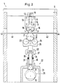
- a laminator 1 has a roller 2 and a counter roller 3, which together form a nip 4.
- Roller 2 and counter roller 3 are arranged within a frame 5 which is part of a housing 6.
- the roller 2 is in this case mounted in bearings 7 which are arranged in frame 5 so as to be displaceable in the vertical direction.
- the counter roller 3 is mounted directly in the frame 5 in a manner not shown in detail.
- the frame 5 has a traverse 8.
- a carrier 9 is arranged below the crossmember 8.
- a screw spindle 10 is rotatably mounted in the carrier 9 and has a torque application surface 11, for example a hexagon.
- the screw 10 is guided in a thread 12 which is firmly connected to the cross member.
- the section 13 thus forms a support with a variable length.
- the carrier 9 has a much lower bending stiffness than the crossmember 8. A change in the length of the section 13 of the screw spindle 10 therefore leads to the carrier 9 bending.
- a deflection of the traverse 8 can be disregarded here, since it is negligibly small.
- bearing elements 14 are arranged distributed over the length of the counter roller 3.
- Each bearing element is formed from a pair of bearing rollers 15, 16.
- the rollers are arranged on both sides of a plane running through the axes 17, 18 of the counter roller 3 and roller 2.
- the bearing rollers are stored in needle bearings 19 which are fastened in bearing blocks 20.
- the bearing blocks 20 are connected directly to the carrier 9.
- the force on the counter roller 3 is applied by the roller 2.
- the roller 2 is in turn acted upon by support elements 21 by a force generating device 22.
- Each support element is formed from a pair of support rollers 23, 24, which are arranged on both sides of the plane passing through the axes 17, 18 of the counter roller 3 and the roller 2.
- the support elements 21 are arranged in pairs on a double lever 25.
- the double lever can be rotated about a pivot point 26 in the manner of a balance beam.
- the pivot point 26 is arranged in a plane which extends between the two support elements 21 forming the pair. It can be arranged below the support elements 21. If the roller 2 bends due to the force applied by the force generating device 22, the support elements 21 can follow this deflection.
- the force on the roller remains evenly distributed. This prevents that where the roller 2 is less strongly bends, an increased pressure is generated in the nip.
- the support elements 21 are supported by means of ball bearings 39 which are fastened in bearing blocks 40, the bearing blocks
- two double levers 25 are provided, which are arranged together on a support lever 27 serving as the basis for the pivot points 26.
- the carrier lever can also be pivoted about a pivot point 28 in the manner of a balance beam.
- the pivot point 28 is arranged in the force generating device 22.
- the force generating device 22 has an eccentric disk 29, on the circumferential surface of which a plunger 30 is supported via an impeller 31.
- the eccentric disc 29 can be driven via a drive wheel 32, which can be rotated via a drive, not shown, for example a chain drive.
- the plunger 30 is mounted in a bearing 33 in the direction of the roller gap toward or away from it.
- a plunger rod 34 is arranged in the plunger 30 and can be displaced in the plunger 30 against the force of a spring arrangement consisting of two plate springs 35, 36 in the plunger 30.
- the fulcrum 28 is arranged on the end of the push rod 34 protruding from the push rod 30.
- the plate springs 35, 36 can be preloaded with the aid of a pre-tensioning device consisting of nuts 37, which are screwed onto a thread applied to the outside of the push rod, and a spacer.
- the pretension of the plate springs 35, 36 is decisive for the pressure that can be generated in the nip 4 with the aid of the force generating device 22.
- a film guide 41, 42 is provided, which extends from an inlet opening 43 in the housing 6 to the nip 4 or from the nip 4 to an outlet opening 44 in the housing 6.
- the laminator works as follows: Before a film combination consisting of a carrier film and a color film is introduced into the laminator 1, the eccentric disc 29 is rotated. As a result, the roller 2 is lowered into the position 2 'shown in dashed lines. This opens the nip 4. The film combination can be inserted and slides on the paper guide 42. Of course, it is also possible that the color film is already in the nip 4 and only the carrier film is fed. As soon as the film combination is in the nip 4, the roller 2 is raised by rotating the eccentric disc 29 and the nip 4 is closed.
- the operator who knows the film combination and knows which pressure in the nip is necessary for satisfactory ink transfer, has previously set the pressure to be generated in the nip 4 with the aid of the nuts 37. In addition, it has previously set the deflection of the counter-roller 3, and thus also the resulting deflection of the roller 2, with the aid of the screw spindle 10. As soon as the nip 4 is closed, the roller 2 and the counter-roller 3 are set in rotation, for example by a gear drive 45, 46, which is driven by a motor and a chain 47, not shown.
- the film combination in the nip 4 is simultaneously transported and pressurized by the movement of the roller 2 and the counter-roller 3, so that ink transfer from the ink film to the carrier film takes place in the nip, gradually over the entire length of the film section to be treated .
Landscapes
- Engineering & Computer Science (AREA)
- Mechanical Engineering (AREA)
- Lining Or Joining Of Plastics Or The Like (AREA)
- Accessory Devices And Overall Control Thereof (AREA)
- Photographic Developing Apparatuses (AREA)
- Advancing Webs (AREA)
- Laminated Bodies (AREA)
Claims (11)
- Machine à presser par laminage (1) présentant un intervalle de laminage (4) constitué entre deux rouleaux ou cylindres (2, 3), dans laquelle l'un des rouleaux (2) est sollicité par une force de pressage, produite par un dispositif de génération de force (22), au moyen d'éléments d'appui (21) répartis sur la longueur du rouleau et susceptibles de se déplacer dans une direction perpendiculaire au plan traversant l'intervalle entre rouleaux, l'autre rouleau (3) étant soutenu par des éléments de palier (14) répartis sur la longueur du rouleau et fixés à un support (9), le support (9) étant susceptible de fléchir et sa flèche étant réglable.
- Machine à presser par laminage selon la revendication 1, caractérisée en ce que les éléments d'appui (21) et les éléments de palier (14) sont disposés décalés les uns par rapport aux autres en laissant subsister des vides.
- Machine à presser par laminage selon la revendication 1 ou 2, caractérisée en ce que les éléments d'appui (21) et/ou les éléments de palier (14) sont constitués par des paires de rouleaux (15, 16; 23, 24), pour chacun desquels un rouleau est disposé respectivement devant et un rouleau est disposé respectivement derrière, un plan passant par les deux axes de rouleaux (17, 18).
- Machine à presser par laminage selon l'une des revendications 1 à 3, caractérisée en ce que le support (9) est en appui sur un cadre (5) par l'intermédiaire d'un pilier de soutien (13) dont la longueur est modifiable.
- Machine à presser par laminage selon la revendication 4, caractérisée en ce que le pilier de soutien (13) de longueur modifiable est constitué par une broche filetée (10) susceptible de tourner dans un taraudage (12) relié au cadre (5).
- Machine à presser par laminage selon la revendication 4 ou 5, caractérisée en ce que le support (9) est en appui sur une traverse (8) du cadre (5) qui présente une rigidité en flexion plusieurs fois supérieure à celle du support.
- Machine à presser par laminage selon l'une des revendications 1 à 6, caractérisée en ce que les éléments d'appui (21) sont disposés par paires sur des leviers doubles (25) du type plateaux de balance, montés pivotants autour d'un axe (26) passant dans le plan s'étendant entre les éléments d'appui respectifs, l'axe (26) étant disposé sur une base susceptible d'être soumise à la force de pressage.
- Machine à presser par laminage selon la revendication 7, caractérisée en ce que deux leviers doubles (25) sont disposés à distance l'un de l'autre sur un levier-support (27) constituant la base et pouvant pivoter autour d'un axe passant par un plan s'étendant entre les deux leviers doubles, l'axe (28) étant relié au dispositif de génération de force (22).
- Machine à presser par laminage selon l'une des revendications 1 à 8, caractérisée en ce que le dispositif de génération de force (22) présente un poussoir (30) qui prend appui sur la surface périphérique d'un disque excentrique (29) monté de façon à pouvoir tourner et à pouvoir être entraîné.
- Machine à presser par laminage selon la revendication 9, caractérisée en ce qu'entre le poussoir (30) et la base est prévu un agencement à ressort (35, 36).
- Machine à presser par laminage selon la revendication 10, caractérisée en ce que l'agencement à ressort présente deux ressorts en rondelle (35, 36) dont la précontrainte est réglable.
Applications Claiming Priority (2)
| Application Number | Priority Date | Filing Date | Title |
|---|---|---|---|
| DE4114313 | 1991-05-02 | ||
| DE4114313A DE4114313C2 (de) | 1991-05-02 | 1991-05-02 | Laminator |
Publications (3)
| Publication Number | Publication Date |
|---|---|
| EP0512267A2 EP0512267A2 (fr) | 1992-11-11 |
| EP0512267A3 EP0512267A3 (en) | 1993-04-07 |
| EP0512267B1 true EP0512267B1 (fr) | 1995-07-12 |
Family
ID=6430812
Family Applications (1)
| Application Number | Title | Priority Date | Filing Date |
|---|---|---|---|
| EP92105969A Expired - Lifetime EP0512267B1 (fr) | 1991-05-02 | 1992-04-07 | Laminoir |
Country Status (4)
| Country | Link |
|---|---|
| US (1) | US5259306A (fr) |
| EP (1) | EP0512267B1 (fr) |
| JP (1) | JP3267670B2 (fr) |
| DE (2) | DE4114313C2 (fr) |
Families Citing this family (12)
| Publication number | Priority date | Publication date | Assignee | Title |
|---|---|---|---|---|
| US5512126A (en) * | 1994-03-11 | 1996-04-30 | Polaroid Corporation | Optical laminator |
| US5552013A (en) * | 1994-06-29 | 1996-09-03 | Kimberly-Clark Corporation | Apparatus and method for rotary bonding |
| NL1003699C2 (nl) * | 1996-07-29 | 1998-02-05 | Johannes Antonius Maria Reinde | Walsconstructie. |
| DE19650297A1 (de) * | 1996-12-04 | 1998-06-18 | Achenbach Buschhuetten Gmbh | Laminator |
| US6287403B1 (en) | 2000-02-15 | 2001-09-11 | Kimberly-Clark Worldwide, Inc. | Support system for rotary function rolls |
| WO2001092110A1 (fr) * | 2000-05-31 | 2001-12-06 | Fogg Filler Company | Ensemble separateur pour dispositif de remplissage et methode connexe |
| US20040163518A1 (en) * | 2001-04-26 | 2004-08-26 | Michael Resterhouse | Separator assembly for filler device and associated method |
| JP4261590B2 (ja) * | 2007-01-31 | 2009-04-30 | 株式会社日立エンジニアリング・アンド・サービス | 無接着剤アラミド−ポリエステル積層体、その製造方法及び製造装置 |
| JP4402734B1 (ja) * | 2008-07-30 | 2010-01-20 | 株式会社日立エンジニアリング・アンド・サービス | 無接着剤アラミド−ポリフェニレンサルファイド積層体の製造方法、回転電機の絶縁部材及び絶縁構造 |
| CN103786411B (zh) * | 2014-02-19 | 2015-08-05 | 苏州博众精工科技有限公司 | 一种自动滚膜机构 |
| JP6544661B2 (ja) * | 2016-10-06 | 2019-07-17 | ユースエンジニアリング株式会社 | ロールプレス装置 |
| CN112221827B (zh) * | 2020-09-29 | 2021-07-20 | 义乌市天天向上工艺品有限公司 | 一种彩带加工设备 |
Family Cites Families (29)
| Publication number | Priority date | Publication date | Assignee | Title |
|---|---|---|---|---|
| US864660A (en) * | 1906-11-12 | 1907-08-27 | William Love | Pressure-roller. |
| US1670894A (en) * | 1925-06-17 | 1928-05-22 | Lorczak Viktor | Expressing machine |
| US1824211A (en) * | 1928-05-02 | 1931-09-22 | August F Jobke | Rolling mill |
| DE970383C (de) * | 1951-02-17 | 1958-09-18 | Kuesters Eduard | Vorrichtung zum Abquetschen der Feuchtigkeit von Textilien |
| DE947065C (de) * | 1951-12-09 | 1956-08-09 | Kuesters Eduard | Vorrichtung zur abquetschenden Behandlung der aus dem Faerbvorgang kommenden Textilien |
| US2718827A (en) * | 1952-10-08 | 1955-09-27 | Farrel Birmingham Co Inc | Paper calender |
| US2800012A (en) * | 1954-12-08 | 1957-07-23 | John H Goetz | Carpet wringer |
| US2851869A (en) * | 1955-01-17 | 1958-09-16 | Quoos Kurt | Squeeze roll apparatus |
| DE1076611B (de) * | 1957-09-19 | 1960-03-03 | Benteler Werke Ag | Vorrichtung zum Abquetschen der Feuchtigkeit aus Textilien |
| DE1111003B (de) * | 1959-03-18 | 1961-07-13 | Ramisch & Co G M B H Dr | Vorrichtung zum Verdichten von mit Impraegniermitteln getraenkten Pappenbahnen od. dgl. |
| NL283877A (fr) * | 1961-12-21 | |||
| US3322586A (en) * | 1963-06-11 | 1967-05-30 | Weyerhaeuser Co | Method and apparatus for joining laminae at the point of convergence of their respective conveyors |
| US3736869A (en) * | 1971-03-16 | 1973-06-05 | Motter J Printing Press Co | Pressure roller device for a rotogravure printing press |
| US3991669A (en) * | 1973-01-17 | 1976-11-16 | Imperial Chemical Industries Limited | Calender presses |
| DE2653682A1 (de) * | 1976-11-26 | 1978-06-01 | Dokoupil Jiri | Durchlauf praege- und buegelmaschine fuer leder mit einfach und schnell austauschbaren praegeelementen |
| US4127066A (en) * | 1977-05-11 | 1978-11-28 | Melvin Sharkey | Adjustable compression roller apparatus |
| NO810897L (no) * | 1981-03-16 | 1982-09-17 | Thune Eureka As | Anordning ved pressvalseaggregat i en strekkmaskin for behandling av virer og filt |
| US4410122A (en) * | 1981-06-01 | 1983-10-18 | Beloit Corporation | Device for widthwise control of web material and method |
| JPS60196206A (ja) * | 1984-03-16 | 1985-10-04 | Ishikawajima Harima Heavy Ind Co Ltd | 圧延機 |
| US4603569A (en) * | 1984-07-20 | 1986-08-05 | Tadeusz Sendzimir | Pressure controlled plate mill |
| US4843673A (en) * | 1987-06-22 | 1989-07-04 | T. Sendzimir, Inc. | Strip wiping system |
| DE3736509A1 (de) * | 1987-10-28 | 1989-05-11 | Hoechst Ag | Vorrichtung zum laminieren und schneiden von fotoresistbahnen |
| US5029310A (en) * | 1989-01-14 | 1991-07-02 | Brother Kogyo Kabushiki Kaisha | Pressure developing device |
| US5057860A (en) * | 1989-10-11 | 1991-10-15 | Brother Kogyo Kabushiki Kaisha | Pressure developing device provided in an image recording apparatus |
| DE3942816A1 (de) * | 1989-12-23 | 1991-06-27 | Du Pont Deutschland | Schichtuebertragungsverfahren zur bilderzeugung und vorrichtung zur durchfuehrung des verfahrens |
| FR2657046B1 (fr) * | 1990-01-16 | 1992-04-30 | Saint Gobain Vitrage Int | Dispositif pour l'assemblage par pressage des vitrages feuilletes. |
| DE4018295C2 (de) * | 1990-06-07 | 1998-12-03 | Du Pont Deutschland | Vorrichtung zum Prüfen der Farbauszüge eines Mehrfarbendrucks |
| DE4023944A1 (de) * | 1990-07-27 | 1992-01-30 | Windmoeller & Hoelscher | Vorrichtung zum stuetzen einer druckbelasteten walze |
| DE4202553C2 (de) * | 1992-01-30 | 1993-11-04 | Du Pont Deutschland | Laminator |
-
1991
- 1991-05-02 DE DE4114313A patent/DE4114313C2/de not_active Expired - Fee Related
-
1992
- 1992-04-07 EP EP92105969A patent/EP0512267B1/fr not_active Expired - Lifetime
- 1992-04-07 DE DE59202849T patent/DE59202849D1/de not_active Expired - Lifetime
- 1992-05-01 US US07/876,944 patent/US5259306A/en not_active Expired - Lifetime
- 1992-05-06 JP JP11382392A patent/JP3267670B2/ja not_active Expired - Fee Related
Also Published As
| Publication number | Publication date |
|---|---|
| JPH05181254A (ja) | 1993-07-23 |
| DE59202849D1 (de) | 1995-08-17 |
| EP0512267A3 (en) | 1993-04-07 |
| DE4114313A1 (de) | 1992-11-05 |
| EP0512267A2 (fr) | 1992-11-11 |
| JP3267670B2 (ja) | 2002-03-18 |
| US5259306A (en) | 1993-11-09 |
| DE4114313C2 (de) | 1994-12-08 |
Similar Documents
| Publication | Publication Date | Title |
|---|---|---|
| DE4224235C2 (de) | Breiten-Einstellvorrichtung für eine Papierbahn, sowie damit ausgestattete Rotationspresse | |
| EP0512267B1 (fr) | Laminoir | |
| DE2913421C3 (de) | Verfahren und Vorrichtung zum Abstreifen von überschüssiger Streichmasse von einer laufenden Bahn | |
| DD232880A5 (de) | Laminierstation | |
| DE4327646C2 (de) | Breiten-Einstellverfahren für eine Papierbahn sowie damit ausgerüstete lithographische Rotationspresse | |
| DE1510215B1 (de) | Presswalzenteil mit gekreuzten Walzen | |
| EP0418476B1 (fr) | Dispositif d'enduction d'un matériau en bande passant le long d'un contre-rouleau | |
| EP1843960B1 (fr) | Procede et dispositif permettant de deplacer un cylindre de pression entraine en rotation contre un cylindre de guidage de materiau | |
| EP0617168A1 (fr) | Dispositif de dosage pour l'enduction de bandes en mouvement, de préférence de papier ou de carton | |
| CH668922A5 (de) | Verfahren und vorrichtung fuer die streichbeschichtung einer sich bewegenden materialbahn. | |
| EP0144536A1 (fr) | Machine pour la fabrication de carton ondulé simple face | |
| DE4400563C2 (de) | Walze in einem Farbwerk oder Feuchtwerk einer Rotationsdruckmaschine | |
| CH628285A5 (en) | Sheet-holding device of a sheet-fed rotary printing machine which is capable of slightly deforming the printing sheet | |
| DE19821603A1 (de) | Längsfalzeinrichtung am Falzapparat von Rotationsdruckmaschinen | |
| DE2427466B2 (de) | Bremsvorrichtung zur Einstellung der Spannung für eine von einer Abwickelmaschine abzuwickelnde Materialbahn in einer Schneidmaschine o.dgl | |
| DE2929535A1 (de) | Rotationsdruckmaschine | |
| EP0175237A2 (fr) | Dispositif d'enlèvement des rouleaux d'encrage dans les machines d'impression | |
| EP0741018A2 (fr) | Dispositif pour le placement d'un rouleau d'application | |
| DE69924466T2 (de) | Abstreifvorrichtung für flüssigkeiten | |
| EP0803354A2 (fr) | Cylindre d'une presse rotative avec un diamètre extérieur modifiable | |
| DE2405859A1 (de) | Verfahren fuer das einstellen sowie anund abstellen von walzen in druckmaschinen und einrichtung zur durchfuehrung des verfahrens | |
| DE19634947C1 (de) | Justiervorrichtung für Druckplatten | |
| EP0845354B1 (fr) | Bac à encre pour presses rotatives | |
| DE3938447C2 (fr) | ||
| DE69911812T2 (de) | Klebstoffauftragsvorrichtung- und verfahren |
Legal Events
| Date | Code | Title | Description |
|---|---|---|---|
| PUAI | Public reference made under article 153(3) epc to a published international application that has entered the european phase |
Free format text: ORIGINAL CODE: 0009012 |
|
| 17P | Request for examination filed |
Effective date: 19920824 |
|
| AK | Designated contracting states |
Kind code of ref document: A2 Designated state(s): DE ES FR GB IT |
|
| PUAL | Search report despatched |
Free format text: ORIGINAL CODE: 0009013 |
|
| AK | Designated contracting states |
Kind code of ref document: A3 Designated state(s): DE ES FR GB IT |
|
| 17Q | First examination report despatched |
Effective date: 19941014 |
|
| RAP1 | Party data changed (applicant data changed or rights of an application transferred) |
Owner name: E.I. DU PONT DE NEMOURS AND COMPANY Owner name: DU PONT DE NEMOURS (DEUTSCHLAND) GMBH |
|
| GRAA | (expected) grant |
Free format text: ORIGINAL CODE: 0009210 |
|
| AK | Designated contracting states |
Kind code of ref document: B1 Designated state(s): DE ES FR GB IT |
|
| PG25 | Lapsed in a contracting state [announced via postgrant information from national office to epo] |
Ref country code: ES Free format text: THE PATENT HAS BEEN ANNULLED BY A DECISION OF A NATIONAL AUTHORITY Effective date: 19950712 |
|
| ET | Fr: translation filed | ||
| REF | Corresponds to: |
Ref document number: 59202849 Country of ref document: DE Date of ref document: 19950817 |
|
| ITF | It: translation for a ep patent filed | ||
| GBT | Gb: translation of ep patent filed (gb section 77(6)(a)/1977) |
Effective date: 19951024 |
|
| PLBE | No opposition filed within time limit |
Free format text: ORIGINAL CODE: 0009261 |
|
| STAA | Information on the status of an ep patent application or granted ep patent |
Free format text: STATUS: NO OPPOSITION FILED WITHIN TIME LIMIT |
|
| 26N | No opposition filed | ||
| REG | Reference to a national code |
Ref country code: GB Ref legal event code: IF02 |
|
| PGFP | Annual fee paid to national office [announced via postgrant information from national office to epo] |
Ref country code: IT Payment date: 20090424 Year of fee payment: 18 Ref country code: FR Payment date: 20090417 Year of fee payment: 18 |
|
| PGFP | Annual fee paid to national office [announced via postgrant information from national office to epo] |
Ref country code: GB Payment date: 20090401 Year of fee payment: 18 |
|
| GBPC | Gb: european patent ceased through non-payment of renewal fee |
Effective date: 20100407 |
|
| REG | Reference to a national code |
Ref country code: FR Ref legal event code: ST Effective date: 20101230 |
|
| PG25 | Lapsed in a contracting state [announced via postgrant information from national office to epo] |
Ref country code: IT Free format text: LAPSE BECAUSE OF NON-PAYMENT OF DUE FEES Effective date: 20100407 Ref country code: GB Free format text: LAPSE BECAUSE OF NON-PAYMENT OF DUE FEES Effective date: 20100407 |
|
| PGFP | Annual fee paid to national office [announced via postgrant information from national office to epo] |
Ref country code: DE Payment date: 20110330 Year of fee payment: 20 |
|
| REG | Reference to a national code |
Ref country code: DE Ref legal event code: R071 Ref document number: 59202849 Country of ref document: DE |
|
| REG | Reference to a national code |
Ref country code: DE Ref legal event code: R071 Ref document number: 59202849 Country of ref document: DE |
|
| PG25 | Lapsed in a contracting state [announced via postgrant information from national office to epo] |
Ref country code: DE Free format text: LAPSE BECAUSE OF EXPIRATION OF PROTECTION Effective date: 20120408 Ref country code: FR Free format text: LAPSE BECAUSE OF NON-PAYMENT OF DUE FEES Effective date: 20100430 |