EP0512267B1 - Laminator - Google Patents
Laminator Download PDFInfo
- Publication number
- EP0512267B1 EP0512267B1 EP92105969A EP92105969A EP0512267B1 EP 0512267 B1 EP0512267 B1 EP 0512267B1 EP 92105969 A EP92105969 A EP 92105969A EP 92105969 A EP92105969 A EP 92105969A EP 0512267 B1 EP0512267 B1 EP 0512267B1
- Authority
- EP
- European Patent Office
- Prior art keywords
- laminator
- roller
- accordance
- nip
- supported
- Prior art date
- Legal status (The legal status is an assumption and is not a legal conclusion. Google has not performed a legal analysis and makes no representation as to the accuracy of the status listed.)
- Expired - Lifetime
Links
Images

Classifications
-
- B—PERFORMING OPERATIONS; TRANSPORTING
- B30—PRESSES
- B30B—PRESSES IN GENERAL
- B30B3/00—Presses characterised by the use of rotary pressing members, e.g. rollers, rings, discs
- B30B3/04—Presses characterised by the use of rotary pressing members, e.g. rollers, rings, discs co-operating with one another, e.g. with co-operating cones
-
- B—PERFORMING OPERATIONS; TRANSPORTING
- B21—MECHANICAL METAL-WORKING WITHOUT ESSENTIALLY REMOVING MATERIAL; PUNCHING METAL
- B21B—ROLLING OF METAL
- B21B13/00—Metal-rolling stands, i.e. an assembly composed of a stand frame, rolls, and accessories
- B21B13/14—Metal-rolling stands, i.e. an assembly composed of a stand frame, rolls, and accessories having counter-pressure devices acting on rolls to inhibit deflection of same under load; Back-up rolls
- B21B13/147—Cluster mills, e.g. Sendzimir mills, Rohn mills, i.e. each work roll being supported by two rolls only arranged symmetrically with respect to the plane passing through the working rolls
-
- B—PERFORMING OPERATIONS; TRANSPORTING
- B32—LAYERED PRODUCTS
- B32B—LAYERED PRODUCTS, i.e. PRODUCTS BUILT-UP OF STRATA OF FLAT OR NON-FLAT, e.g. CELLULAR OR HONEYCOMB, FORM
- B32B37/00—Methods or apparatus for laminating, e.g. by curing or by ultrasonic bonding
- B32B37/0046—Methods or apparatus for laminating, e.g. by curing or by ultrasonic bonding characterised by constructional aspects of the apparatus
- B32B37/0053—Constructional details of laminating machines comprising rollers; Constructional features of the rollers
-
- B—PERFORMING OPERATIONS; TRANSPORTING
- B32—LAYERED PRODUCTS
- B32B—LAYERED PRODUCTS, i.e. PRODUCTS BUILT-UP OF STRATA OF FLAT OR NON-FLAT, e.g. CELLULAR OR HONEYCOMB, FORM
- B32B38/00—Ancillary operations in connection with laminating processes
- B32B38/18—Handling of layers or the laminate
- B32B38/1866—Handling of layers or the laminate conforming the layers or laminate to a convex or concave profile
Definitions
- the invention relates to a laminator.
- Laminators are used, for example, to check color separations of a multicolor print.
- an image carrier which has a sticky surface on the areas to be colored, is passed through a nip together with a color film, which has a color layer and lies with this color layer on the carrier film.
- the two rollers forming the nip press the ink film and the carrier film against one another under pressure. The paint sticks to the sticky areas and peels off the color film.
- the invention is based on the object of specifying a laminator which substantially reduces the risk of the films running when the pressure in the roll nip is as uniform as possible.
- a laminator with a roll nip formed by two rolls, in which one of the rolls is acted upon by a pressing force generated by a force generating device by supporting elements distributed over the length of the roll and movable in a direction perpendicular to a plane passing through the roll nip, wherein the other roller is supported by bearing elements distributed over the length of the roller, which are fastened to a carrier, the carrier being bendable and the deflection being adjustable.
- the bearing elements which are arranged on the carrier, inevitably follow the deflection of the carrier. Accordingly, the roller supported on the bearing elements can also be bent in accordance with this bending line if a corresponding force is applied to it by its counter roller. This force is applied via the force generating device, which transfers the pressing force via the support elements to the counter roller.
- the support elements can be moved, specifically in a plane perpendicular to the plane passing through the nip. The new laminator therefore creates a nip that is no longer completely flat, but has a deflection determined by the deflection of the support.
- the support elements that generate the pressing force but are evenly distributed over the length of the roller, it can be ensured that despite the deflection in the nip, there is an even pressure distribution.
- the deflection leads to an automatic centering of the foils running through the nip.
- the evenly distributed support elements lead to an even pressure distribution in the nip, so that color separations can be obtained with a high quality.
- the support elements and the bearing elements are offset from one another with a gap. The pressure distribution in the nip is thereby further evened out.
- the support elements and / or the bearing elements are formed by pairs of rollers, in each of which a roller is arranged in front and a roller behind a plane running through both roller axes.
- the rollers are therefore not only supported in a direction perpendicular to the plane running through the roller gap, but forces are also absorbed which act in the direction of the movement path of the foils (or in the opposite direction), that is to say so-called transverse forces.
- Such forces can be applied, for example, by the foils. Of course, these forces are much lower than the forces that create the pressure in the nip.
- the deflection of the rollers can be adjusted more precisely. It then runs only in one plane in which the two roller axes are also located.
- the carrier is preferably supported on a frame via a length-adjustable support.
- the length-adjustable support defines the apex of the deflection of the beam and thus also of the roll gap.
- the deflection can also be adjusted by changing the length of the support.
- the length-adjustable support is formed by a screw spindle which is rotatable in a thread connected to the frame.
- the screw spindle is rotatably mounted in the carrier.
- the thread enables a relatively fine translation of the rotary movement into a longitudinal movement, so that the deflection of the carrier can be adjusted very finely and with great accuracy.
- the carrier is advantageously supported on a crossbeam of the frame which has a bending stiffness that is many times greater than that of the carrier.
- a change in the length of the support then has practically only the effect that the deflection of the beam changes. Deflection of the crossbeam can be disregarded, since this is negligible due to the great flexural rigidity of the crossbeam compared to the deflection of the beam.
- the support elements are advantageously arranged in pairs on beam-like double levers which can be pivoted about an axis lying in a plane running between the respective support elements, the axis being arranged on a base to which the pressing force can be applied. Because the support elements are no longer rigidly arranged in a line next to each other, but on beam-like double levers, they can follow the deflection of the roller. Nevertheless, each support element can transmit the same amount of pressing force. This ensures that a uniform pressure distribution can be achieved in the entire nip despite the deflection of the rolls.
- two double levers spaced apart are arranged on a support lever forming the base, which can be pivoted about an axis lying in a plane running between the two double levers, the axis being connected to the force generating device.
- This arrangement is particularly preferred for longer rolls.
- the individual support elements can be pressed against the roller even with a deflected roller with a relatively uniform distribution of force. The pressure in the nip can thus be made very even.
- the force generating device preferably has a plunger which is supported on the peripheral surface of a rotatably mounted and drivable eccentric disk.
- the plunger is raised or lowered by turning the eccentric disc, i.e. moved towards or away from the nip. Due to the eccentric disc, a relatively large amount of movement of the ram and therefore a correspondingly large possibility of movement of the support elements is possible. It can even be provided that one roller is lowered and the nip opens.
- the force that can be applied to the tappet and thus the pressing force prevailing in the nip is dependent on the torque with which the eccentric disc is driven and the gradient of the peripheral surface of the eccentric disc relative to a cylinder surface.
- a spring arrangement is provided between the plunger and the base.
- the spring arrangement is ultimately decisive for the pressure prevailing in the nip.
- the spring arrangement has two disc springs, the preload of which is adjustable.
- the preload of the disc springs is decisive for the pressure in the nip.
- a laminator 1 has a roller 2 and a counter roller 3, which together form a nip 4.
- Roller 2 and counter roller 3 are arranged within a frame 5 which is part of a housing 6.
- the roller 2 is in this case mounted in bearings 7 which are arranged in frame 5 so as to be displaceable in the vertical direction.
- the counter roller 3 is mounted directly in the frame 5 in a manner not shown in detail.
- the frame 5 has a traverse 8.
- a carrier 9 is arranged below the crossmember 8.
- a screw spindle 10 is rotatably mounted in the carrier 9 and has a torque application surface 11, for example a hexagon.
- the screw 10 is guided in a thread 12 which is firmly connected to the cross member.
- the section 13 thus forms a support with a variable length.
- the carrier 9 has a much lower bending stiffness than the crossmember 8. A change in the length of the section 13 of the screw spindle 10 therefore leads to the carrier 9 bending.
- a deflection of the traverse 8 can be disregarded here, since it is negligibly small.
- bearing elements 14 are arranged distributed over the length of the counter roller 3.
- Each bearing element is formed from a pair of bearing rollers 15, 16.
- the rollers are arranged on both sides of a plane running through the axes 17, 18 of the counter roller 3 and roller 2.
- the bearing rollers are stored in needle bearings 19 which are fastened in bearing blocks 20.
- the bearing blocks 20 are connected directly to the carrier 9.
- the force on the counter roller 3 is applied by the roller 2.
- the roller 2 is in turn acted upon by support elements 21 by a force generating device 22.
- Each support element is formed from a pair of support rollers 23, 24, which are arranged on both sides of the plane passing through the axes 17, 18 of the counter roller 3 and the roller 2.
- the support elements 21 are arranged in pairs on a double lever 25.
- the double lever can be rotated about a pivot point 26 in the manner of a balance beam.
- the pivot point 26 is arranged in a plane which extends between the two support elements 21 forming the pair. It can be arranged below the support elements 21. If the roller 2 bends due to the force applied by the force generating device 22, the support elements 21 can follow this deflection.
- the force on the roller remains evenly distributed. This prevents that where the roller 2 is less strongly bends, an increased pressure is generated in the nip.
- the support elements 21 are supported by means of ball bearings 39 which are fastened in bearing blocks 40, the bearing blocks
- two double levers 25 are provided, which are arranged together on a support lever 27 serving as the basis for the pivot points 26.
- the carrier lever can also be pivoted about a pivot point 28 in the manner of a balance beam.
- the pivot point 28 is arranged in the force generating device 22.
- the force generating device 22 has an eccentric disk 29, on the circumferential surface of which a plunger 30 is supported via an impeller 31.
- the eccentric disc 29 can be driven via a drive wheel 32, which can be rotated via a drive, not shown, for example a chain drive.
- the plunger 30 is mounted in a bearing 33 in the direction of the roller gap toward or away from it.
- a plunger rod 34 is arranged in the plunger 30 and can be displaced in the plunger 30 against the force of a spring arrangement consisting of two plate springs 35, 36 in the plunger 30.
- the fulcrum 28 is arranged on the end of the push rod 34 protruding from the push rod 30.
- the plate springs 35, 36 can be preloaded with the aid of a pre-tensioning device consisting of nuts 37, which are screwed onto a thread applied to the outside of the push rod, and a spacer.
- the pretension of the plate springs 35, 36 is decisive for the pressure that can be generated in the nip 4 with the aid of the force generating device 22.
- a film guide 41, 42 is provided, which extends from an inlet opening 43 in the housing 6 to the nip 4 or from the nip 4 to an outlet opening 44 in the housing 6.
- the laminator works as follows: Before a film combination consisting of a carrier film and a color film is introduced into the laminator 1, the eccentric disc 29 is rotated. As a result, the roller 2 is lowered into the position 2 'shown in dashed lines. This opens the nip 4. The film combination can be inserted and slides on the paper guide 42. Of course, it is also possible that the color film is already in the nip 4 and only the carrier film is fed. As soon as the film combination is in the nip 4, the roller 2 is raised by rotating the eccentric disc 29 and the nip 4 is closed.
- the operator who knows the film combination and knows which pressure in the nip is necessary for satisfactory ink transfer, has previously set the pressure to be generated in the nip 4 with the aid of the nuts 37. In addition, it has previously set the deflection of the counter-roller 3, and thus also the resulting deflection of the roller 2, with the aid of the screw spindle 10. As soon as the nip 4 is closed, the roller 2 and the counter-roller 3 are set in rotation, for example by a gear drive 45, 46, which is driven by a motor and a chain 47, not shown.
- the film combination in the nip 4 is simultaneously transported and pressurized by the movement of the roller 2 and the counter-roller 3, so that ink transfer from the ink film to the carrier film takes place in the nip, gradually over the entire length of the film section to be treated .
Description
Die Erfindung betrifft einen Laminator.The invention relates to a laminator.
Laminatoren werden beispielsweise verwendet, um Farbauszüge eines Mehrfarbendruckes zu prüfen. Hierbei wird ein Bildträger, der an den zu färbenden Bereichen eine klebrige Oberfläche aufweist, zusammen mit einer Farbfolie, die eine Farbschicht aufweist und mit dieser Farbschicht auf der Trägerfolie aufliegt, durch einen Walzenspalt geführt. Die beiden den Walzenspalt bildenden Walzen pressen die Farbfolie und die Trägerfolie unter Druck aufeinander. An den klebrigen Bereichen bleibt die Farbe hängen und löst sich von der Farbfolie ab.Laminators are used, for example, to check color separations of a multicolor print. Here, an image carrier, which has a sticky surface on the areas to be colored, is passed through a nip together with a color film, which has a color layer and lies with this color layer on the carrier film. The two rollers forming the nip press the ink film and the carrier film against one another under pressure. The paint sticks to the sticky areas and peels off the color film.
Hierbei ist es von Bedeutung, daß nicht nur ein relativ hoher Druck erzeugt wird, sondern der Druck auch gleichmäßig über die Länge des Walzenspaltes, d.h. über die Längsausdehnung der Walzen, verteilt wird. Die den Druck im Walzenspalt erzeugenden Kräfte führen zu einem Verbiegen der Walzen. Dieses Verbiegen führt zu einer ungleichmäßigen Druckverteilung im Walzenspalt, so daß beispielsweise in der Mitte des Walzenspaltes ein anderer Druck als an den Enden ausgeübt wird. Dies führt bei der Erzeugung von Farbauszügen zu Ungleichmäßigkeiten, die einen Fehler in den Farbauszügen vortäuschen können.It is important here that not only is a relatively high pressure generated, but the pressure is also distributed uniformly over the length of the roll gap, ie over the longitudinal extent of the rolls. The pressure Forces in the nip cause the rolls to bend. This bending leads to an uneven pressure distribution in the nip, so that, for example, a different pressure is exerted in the middle of the nip than at the ends. This leads to irregularities in the generation of color separations, which can simulate an error in the color separations.
Man hat deswegen versucht, ein Durchbiegen der Walzen zu verhindern. Bei einer aus US-PS 4 127 066 bekannten Anordnung ist die untere Walze des den Walzenspalt bildenden Walzenpaares in einem Rahmen fest angeordnet, während die obere Walze in Lagern gelagert ist, die in dem Rahmen vertikal verschiebbar sind. Ein Paar von Stützwalzen wirkt von oben auf die obere Walze, wobei die Stützwalzen in einem Hilfsrahmen gelagert sind, der über eine Schraubspindel mit dem Rahmen verbunden ist. Durch Verdrehen der Schraubspindel läßt sich der Druck der Stützwalzen auf die obere Walze und damit der Druck im Walzenspalt verstärken oder vermindern. Bei längeren Walzen muß jedoch auch die Stützwalze entsprechend lang ausgebildet sein mit der Gefahr, daß sich nunmehr die Stützwalze durchbiegt. Die Kraftaufbringung auf die obere Walze erfolgt dann im wesentlichen im Bereich der beiden Lager der Stützwalzen, was zu einer W-Form des Walzenspaltes mit einer entsprechend ungleichmäßigen Verteilung des Druckes führt. Bei relativ kurzen Walzen, bei denen praktisch keine spürbare Durchbiegung auftritt, hat es sich herausgestellt, daß die hindurchgeführten Bahnen verlaufen, d.h. ihre Bewegungsrichtung weicht ohne Hilfsmaßnahmen von einer Richtung rechtwinklig zur Längserstreckung des Walzenspaltes ab. Dies kann insbesondere an den Rändern der Folie zu einer Faltenbildung führen. Eine Faltenbildung ist aber beim Erzeugen von Farbauszügen nicht annehmbar, da bei Auftreten von Falten die gewünschte Farbübertragung nicht mehr gewährleistet ist, insbesondere wenn beim Erzeugen von Farbauszügen mehrere Farben, in der Regel vier, hintereinander in der gleichen Art und Weise aufgebracht werden müssen.Therefore, attempts have been made to prevent the rollers from bending. In an arrangement known from US Pat. No. 4,127,066, the lower roller of the pair of rollers forming the nip is fixedly arranged in a frame, while the upper roller is mounted in bearings which are vertically displaceable in the frame. A pair of support rollers acts on the upper roller from above, the support rollers being mounted in an auxiliary frame which is connected to the frame via a screw spindle. By turning the screw spindle, the pressure of the support rollers on the upper roller and thus the pressure in the roller gap can be increased or decreased. In the case of longer rolls, however, the back-up roll must also be made correspondingly long, with the risk that the back-up roll now bends. The application of force to the upper roller then takes place essentially in the region of the two bearings of the support rollers, which leads to a W-shape of the roller gap with a correspondingly uneven distribution of the pressure. In the case of relatively short rolls, in which there is practically no noticeable deflection, it has been found that the webs that are passed run, ie their direction of movement deviates from a direction perpendicular to the longitudinal extent of the roll nip without auxiliary measures. This can lead to wrinkling, especially at the edges of the film. However, wrinkling is not acceptable when producing color separations, since the desired color transfer is no longer guaranteed when wrinkles occur, in particular if several colors, usually four, have to be applied in succession in the same way when producing color separations.
Der Erfindung liegt die Aufgabe zugrunde, einen Laminator anzugeben, der bei einer möglichst gleichmäßigen Druckverteilung im Walzenspalt das Risiko des Verlaufens der Folien wesentlich vermindert.The invention is based on the object of specifying a laminator which substantially reduces the risk of the films running when the pressure in the roll nip is as uniform as possible.
Diese Aufgabe wird durch einen Laminator gelöst mit einem durch zwei Walzen gebildeten Walzenspalt, bei dem eine der Walzen durch über die Länge der Walze verteilte und in einer Richtung senkrecht zu einer den Walzenspalt durchsetzenden Ebene bewegbare Stützelemente mit einer durch eine Krafterzeugungseinrichtung erzeugten Preßkraft beaufschlagt ist, wobei die andere Walze durch über die Länge der Walze verteilte Lagerelemente abgestützt ist, die an einem Träger befestigt sind, wobei der Träger biegbar ist und die Durchbiegung einstellbar ist.This object is achieved by a laminator with a roll nip formed by two rolls, in which one of the rolls is acted upon by a pressing force generated by a force generating device by supporting elements distributed over the length of the roll and movable in a direction perpendicular to a plane passing through the roll nip, wherein the other roller is supported by bearing elements distributed over the length of the roller, which are fastened to a carrier, the carrier being bendable and the deflection being adjustable.
Die Lagerelemente, die an dem Träger angeordnet sind, folgen zwangsläufig der Durchbiegung des Trägers. Dementsprechend kann auch die an den Lagerelementen abgestützte Walze entsprechend dieser Biegelinie durchgebogen werden, wenn sie von ihrer Gegenwalze mit einer entsprechenden Kraft beaufschlagt wird. Diese Kraft wird über die Krafterzeugungseinrichtung aufgebracht, die die Preßkraft über die Stützelemente auf die Gegenwalze überträgt. Um der Durchbiegung folgen zu können, sind die Stützelemente bewegbar, und zwar in einer Ebene senkrecht zur den Walzenspalt durchsetzenden Ebene. Es wird daher mit dem neuen Laminator ein Walzenspalt erzeugt, der nicht mehr völlig eben ist, sondern eine durch die Durchbiegung des Trägers bestimmte Durchbiegung aufweist. Da die Stützelemente, die die Preßkraft erzeugen, aber über die Länge der Walze gleichmäßig verteilt sind, läßt sich gewährleisten, daß trotz der Durchbiegung im Walzenspalt eine gleichmäßige Druckverteilung vorherrscht. Die Durchbiegung führt zu einer automatischen Zentrierung der durch den Walzenspalt laufenden Folien. Die gleichmäßig verteilten Stützelemente führen zu einer gleichmäßigen Druckverteilung im Walzenspalt, so daß Farbauszüge mit einer hohen Qualität gewonnen werden können.The bearing elements, which are arranged on the carrier, inevitably follow the deflection of the carrier. Accordingly, the roller supported on the bearing elements can also be bent in accordance with this bending line if a corresponding force is applied to it by its counter roller. This force is applied via the force generating device, which transfers the pressing force via the support elements to the counter roller. In order to be able to follow the deflection, the support elements can be moved, specifically in a plane perpendicular to the plane passing through the nip. The new laminator therefore creates a nip that is no longer completely flat, but has a deflection determined by the deflection of the support. Since the support elements that generate the pressing force, but are evenly distributed over the length of the roller, it can be ensured that despite the deflection in the nip, there is an even pressure distribution. The deflection leads to an automatic centering of the foils running through the nip. The evenly distributed support elements lead to an even pressure distribution in the nip, so that color separations can be obtained with a high quality.
Hierbei ist bevorzugt, daß die Stützelemente und die Lagerelemente auf Lücke versetzt zueinander angeordnet sind. Die Druckverteilung im Walzenspalt wird dadurch weiter vergleichmäßigt.It is preferred that the support elements and the bearing elements are offset from one another with a gap. The pressure distribution in the nip is thereby further evened out.
In einer weiteren vorteilhaften Ausführungsform sind die Stützelemente und/oder die Lagerelemente durch Rollenpaare gebildet, bei denen jeweils eine Rolle vor und eine Rolle hinter einer durch beide Walzenachsen verlaufenden Ebene angeordnet ist. Die Walzen werden also nicht nur in einer Richtung senkrecht zu der durch den Walzenspalt verlaufenden Ebene unterstützt, sondern es werden auch Kräfte aufgenommen, die in Richtung der Bewegungsbahn der Folien (oder in entgegengesetzter Richtung) wirken, also sogenannte Querkräfte. Derartige Kräfte können beispielsweise von den Folien aufgebracht werden. Natürlich sind diese Kräfte wesentlich geringer als die Kräfte, die den Druck im Walzenspalt erzeugen. Die Durchbiegung der Walzen kann dadurch genauer eingestellt werden. Sie verläuft dann lediglich in einer Ebene, in der auch die beiden Walzenachsen liegen.In a further advantageous embodiment, the support elements and / or the bearing elements are formed by pairs of rollers, in each of which a roller is arranged in front and a roller behind a plane running through both roller axes. The rollers are therefore not only supported in a direction perpendicular to the plane running through the roller gap, but forces are also absorbed which act in the direction of the movement path of the foils (or in the opposite direction), that is to say so-called transverse forces. Such forces can be applied, for example, by the foils. Of course, these forces are much lower than the forces that create the pressure in the nip. The deflection of the rollers can be adjusted more precisely. It then runs only in one plane in which the two roller axes are also located.
Bevorzugterweise ist der Träger über eine längenveränderbare Stütze an einem Rahmen abgestützt. Die längenveränderbare Stütze definiert den Scheitelpunkt der Durchbiegung des Trägers und somit auch des Walzenspalts. Durch die Veränderung der Länge der Stütze läßt sich auch die Durchbiegung einstellen.The carrier is preferably supported on a frame via a length-adjustable support. The length-adjustable support defines the apex of the deflection of the beam and thus also of the roll gap. The deflection can also be adjusted by changing the length of the support.
Hierbei ist bevorzugt, daß die längenveränderbare Stütze durch eine Schraubspindel gebildet ist, die in einem mit dem Rahmen verbundenen Gewinde drehbar ist. Die Schraubspindel ist in dem Träger drehbar gelagert. Durch Drehen der Schraubspindel wird der Abstand zwischen Träger und Rahmen vergrößert oder verkleinert, d.h. die wirksame Länge der Stütze verändert. Das Gewinde ermöglicht eine relativ feine Übersetzung der Drehbewegung in eine Längsbewegung, so daß die Durchbiegung des Trägers sehr fein und mit hoher Genauigkeit eingestellt werden kann.It is preferred that the length-adjustable support is formed by a screw spindle which is rotatable in a thread connected to the frame. The screw spindle is rotatably mounted in the carrier. By turning the screw spindle, the distance between the support and the frame is increased or decreased, i.e. changed the effective length of the support. The thread enables a relatively fine translation of the rotary movement into a longitudinal movement, so that the deflection of the carrier can be adjusted very finely and with great accuracy.
Mit Vorteil ist der Träger an eine Traverse des Rahmens abgestützt, die eine um ein Vielfaches größere Biegesteifigkeit als der Träger aufweist. Eine Längenveränderung der Stütze hat dann praktisch ausschließlich die Wirkung, daß sich die Durchbiegung des Trägers ändert. Eine Durchbiegung der Traverse kann außer acht gelassen werden, da diese aufgrund der großen Biegesteifigkeit der Traverse gegenüber der Durchbiegung des Trägers vernachlässigbar ist.The carrier is advantageously supported on a crossbeam of the frame which has a bending stiffness that is many times greater than that of the carrier. A change in the length of the support then has practically only the effect that the deflection of the beam changes. Deflection of the crossbeam can be disregarded, since this is negligible due to the great flexural rigidity of the crossbeam compared to the deflection of the beam.
Mit Vorteil sind die Stützelemente paarweise auf waagebalkenartigen Doppelhebeln angeordnet, die um eine in einer zwischen den jeweiligen Stützelementen verlaufenden Ebene liegende Achse verschwenkbar sind, wobei die Achse auf einer mit der Preßkraft beaufschlagbaren Basis angeordnet ist. Dadurch, daß die Stützelemente nicht mehr starr in einer Linie nebeneinander angeordnet sind, sondern auf waagebalkenartigen Doppelhebeln, können sie der Durchbiegung der Walze folgen. Trotzdem kann jedes Stützelement den gleichen Anteil an Preßkraft übertragen. Hierdurch wird erreicht, daß trotz der Durchbiegung der Walzen im gesamten Walzenspalt eine gleichmäßige Druckverteilung erzielt werden kann.The support elements are advantageously arranged in pairs on beam-like double levers which can be pivoted about an axis lying in a plane running between the respective support elements, the axis being arranged on a base to which the pressing force can be applied. Because the support elements are no longer rigidly arranged in a line next to each other, but on beam-like double levers, they can follow the deflection of the roller. Nevertheless, each support element can transmit the same amount of pressing force. This ensures that a uniform pressure distribution can be achieved in the entire nip despite the deflection of the rolls.
Auch ist bevorzugt, daß zwei Doppelhebel mit Abstand zueinander auf einem die Basis bildenden Trägerhebel angeordnet sind, der um eine in einer zwischen den beiden Doppelhebeln verlaufenden Ebene liegenden Achse verschwenkbar ist, wobei die Achse mit der Krafterzeugungseinrichtung verbunden ist. Diese Anordnung ist insbesondere bei längeren Walzen bevorzugt. Hierbei lassen sich die einzelnen Stützelemente auch bei einer durchgebogenen Walze mit einer relativ gleichmäßigen Kraftverteilung an die Walze anpressen. Der Druck im Walzenspalt kann dadurch sehr gleichmäßig gestaltet werden.It is also preferred that two double levers spaced apart are arranged on a support lever forming the base, which can be pivoted about an axis lying in a plane running between the two double levers, the axis being connected to the force generating device. This arrangement is particularly preferred for longer rolls. Here, the individual support elements can be pressed against the roller even with a deflected roller with a relatively uniform distribution of force. The pressure in the nip can thus be made very even.
Bevorzugterweise weist die Krafterzeugungseinrichtung einen Stößel auf, der sich auf der Umfangsfläche einer drehbar gelagerten und antreibbaren Exzenterscheibe abstützt. Durch das Verdrehen der Exzenterscheibe wird der Stößel angehoben oder abgesenkt, d.h. in Richtung auf den Walzenspalt zu oder von ihm weg bewegt. Durch die Exzenterscheibe ist ein relativ großes Bewegungsspiel des Stößels und deswegen auch eine entsprechend große Bewegungsmöglichkeit der Stützelemente möglich. Man kann hierbei sogar vorsehen, daß die eine Walze abgesenkt wird und den Walzenspalt öffnet. Die Kraft, die auf den Stößel aufgebracht werden kann und damit die im Walzenspalt herrschende Preßkraft, ist abhängig von dem Drehmoment, mit dem die Exzenterscheibe angetrieben wird und der Steigung der Umfangsfläche der Exzenterscheibe gegenüber einer Zylinderfläche.The force generating device preferably has a plunger which is supported on the peripheral surface of a rotatably mounted and drivable eccentric disk. The plunger is raised or lowered by turning the eccentric disc, i.e. moved towards or away from the nip. Due to the eccentric disc, a relatively large amount of movement of the ram and therefore a correspondingly large possibility of movement of the support elements is possible. It can even be provided that one roller is lowered and the nip opens. The force that can be applied to the tappet and thus the pressing force prevailing in the nip is dependent on the torque with which the eccentric disc is driven and the gradient of the peripheral surface of the eccentric disc relative to a cylinder surface.
Hierbei ist bevorzugt, daß zwischen Stößel und Basis eine Federanordnung vorgesehen ist. Die Federanordnung ist letztendlich ausschlaggebend für den im Walzenspalt herrschenden Druck.It is preferred that a spring arrangement is provided between the plunger and the base. The spring arrangement is ultimately decisive for the pressure prevailing in the nip.
Hierbei ist bevorzugt, daß die Federanordnung zwei Tellerfedern aufweist, deren Vorspannung einstellbar ist. Die Vorspannung der Tellerfedern ist entscheidend für den im Walzenspalt herrschenden Druck.It is preferred here that the spring arrangement has two disc springs, the preload of which is adjustable. The preload of the disc springs is decisive for the pressure in the nip.
Die Erfindung wird im folgenden anhand eines bevorzugten Ausführungsbeispiels in Verbindung mit der Zeichnung beschrieben. Hierin zeigen:
- Fig. 1
- eine Frontansicht eines Laminators, teilweise im Aufriß, und
- Fig. 2
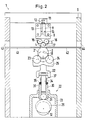
- eine Seitenansicht des Laminators, teilweise im Aufriß.
- Fig. 1
- a front view of a laminator, partly in elevation, and
- Fig. 2
- a side view of the laminator, partly in elevation.
Ein Laminator 1 weist eine Walze 2 und eine Gegenwalze 3 auf, die zusammen einen Walzenspalt 4 bilden. Walze 2 und Gegenwalze 3 sind innerhalb eines Rahmens 5 angeordnet, der Teil eines Gehäuses 6 ist. Die Walze 2 ist hierbei in Lagern 7 gelagert, die in Rahmen 5 in vertikaler Richtung verschiebbar angeordnet sind. Die Gegenwalze 3 ist in nicht naher dargestellter Weise unmittelbar im Rahmen 5 gelagert.A laminator 1 has a
Der Rahmen 5 weist eine Traverse 8 auf. Unterhalb der Traverse 8 ist ein Träger 9 angeordnet. Im Träger 9 ist eine Schraubspindel 10 drehbar gelagert, die eine Drehmomentangriffsfläche 11, beispielsweise einen Sechskant, aufweist. Die Schraubspindel 10 ist in einem mit der Traverse fest verbundenen Gewinde 12 geführt. Bei einem Verdrehen der Schraubspindel 11 verändert sich somit die Länge eines zwischen der Traverse 8 und dem Träger 9 frei liegenden Abschnitts 13 der Schraubspindel. Der Abschnitt 13 bildet somit eine Stütze mit veränderbarer Länge. Der Träger 9 hat eine wesentlich geringere Biegesteifigkeit als die Traverse 8. Eine Längenänderung des Abschnitts 13 der Schraubspindel 10 führt also dazu, daß sich der Träger 9 durchbiegt. Eine Durchbiegung der Traverse 8 kann dabei außer Betracht bleiben, da sie vernachlässigbar klein ist.The
An der Unterseite des Trägers 9 sind über die Länge der Gegenwalze 3 verteilt fünf Lagerelemente 14 angeordnet. Jedes Lagerelement ist aus einem Paar Lagerrollen 15, 16 gebildet. Die Rollen sind auf beiden Seiten einer durch die Achsen 17, 18 von Gegenwalze 3 und Walze 2 verlaufenden Ebene angeordnet. Die Lagerrollen sind in Nadellagern 19 gelagert, die in Lagerböcken 20 befestigt sind. Die Lagerböcke 20 sind unmittelbar mit dem Träger 9 verbunden.On the underside of the
Wenn nun der Träger 9 durch eine Änderung der Länge des Abschnitts 13 der Schraubspindel 10 eine Durchbiegung erfährt, folgen die Lagerelemente 14 im wesentlichen dieser Biegelinie. Sobald auf die Gegenwalze 3 eine Kraft ausgeübt wird, die zu einer Durchbiegung der Gegenwalze 3 führt, wird sich die Gegenwalze 3 solange durchbiegen, bis sie an allen Lagerelementen 14 anliegt Somit kann auch eine Biegelinie der Gegenwalze 3 definiert werden.If the
Die Kraft auf die Gegenwalze 3 wird durch die Walze 2 aufgebracht. Die Walze 2 wird wiederum über Stützelemente 21 von einer Krafterzeugungseinrichtung 22 mit Kraft beaufschlagt. Jedes Stützelement ist aus einem Paar von Stützrollen 23, 24 gebildet, die auf beiden Seiten der durch die Achsen 17, 18 der Gegenwalze 3 und der Walze 2 verlaufenden Ebene angeordnet sind. Die Stützelemente 21 sind paarweise auf einem Doppelhebel 25 angeordnet. Der Doppelhebel ist um einen Drehpunkt 26 nach Art eines Waagebalkens drehbar. Der Drehpunkt 26 ist in einer Ebene angeordnet, die sich zwischen den beiden das Paar bildenden Stützelementen 21 erstreckt. Er kann dabei unterhalb der Stützelemente 21 angeordnet sein. Wenn sich die Walze 2 aufgrund der durch die Krafterzeugungseinrichtung 22 aufgebrachten Kraft durchbiegt, können die Stützelemente 21 dieser Durchbiegung folgen. Die Kraft auf die Walze bleibt also gleichmäßig verteilt. Hierdurch wird verhindert, daß an den Stellen, an denen sich die Walze 2 weniger stark durchbiegt, ein erhöhter Druck im Walzenspalt erzeugt wird. Die Stützelemente 21 sind mit Hilfe von Kugellagern 39, die in Lagerböcken 40 befestigt sind, gelagert, wobei die Lagerböcke 40 auf den Doppelhebeln 25 befestigt sind.The force on the
Im vorliegenden Ausführungsbeispiel sind zwei Doppelhebel 25 vorgesehen, die gemeinsam auf einem als Basis für die Drehpunkte 26 dienenden Trägerhebel 27 angeordnet sind. Der Trägerhebel ist um einen Drehpunkt 28 ebenfalls nach Art eines Waagebalkens verschwenkbar. Der Drehpunkt 28 ist in der Krafterzeugungseinrichtung 22 angeordnet.In the present exemplary embodiment, two
Die Krafterzeugungseinrichtung 22 weist eine Exzenterscheibe 29 auf, auf deren Umfangsfläche sich ein Stößel 30 über ein Laufrad 31 abstützt. Die Exzenterscheibe 29 kann über ein Antriebsrad 32 angetrieben werden, das über einen nicht näher dargestellten Antrieb, beispielsweise einen Kettenantrieb, verdreht werden kann.The
Zur Bewegung ist der Stößel 30 in einem Lager 33 in Richtung auf den Walzenspalt zu oder von ihm weg verschiebbar gelagert.For movement, the
Im Stößel 30 ist eine Stößelstange 34 angeordnet, die im Stößel 30 gegen die Kraft einer aus zwei Tellerfedern 35, 36 bestehenden Federanordnung im Stößel 30 verschiebbar ist. Am aus dem Stößel 30 herausragenden Ende der Stößelstange 34 ist der Drehpunkt 28 angeordnet. Die Tellerfedern 35, 36 sind mit Hilfe einer aus Muttern 37, die auf ein auf der Außenseite der Stößelstange aufgebrachtes Gewinde aufgeschraubt sind, und einem Distanzstück bestehenden Vorspanneinrichtung vorspannbar. Die Vorspannung der Tellerfedern 35, 36 ist entscheidend für den mit Hilfe der Krafterzeugungseinrichtung 22 im Walzenspalt 4 erzeugbaren Druck.A
Zur Führung einer Trägerfolie und einer Farbfolie ist eine Folienführung 41, 42 vorgesehen, die sich von einer Eingangsöffnung 43 im Gehäuse 6 zum Walzenspalt 4 bzw. vom Walzenspalt 4 zu einer Ausgangsöffnung 44 im Gehäuse 6 erstrecken.For guiding a carrier film and a color film, a
Der Laminator arbeitet wie folgt:
Bevor eine aus einer Trägerfolie und einer Farbfolie bestehende Folienkombination in den Laminator 1 eingeführt wird, wird die Exzenterscheibe 29 verdreht. Hierdurch wird die Walze 2 in die gestrichelt dargestellte Position 2' abgesenkt. Der Walzenspalt 4 ist hierdurch geöffnet. Die Folienkombination kann eingeführt werden und gleitet auf der Papierführung 42 weiter. Natürlich ist es auch möglich, daß sich bereits die Farbfolie in dem Walzenspalt 4 befindet und lediglich die Trägerfolie zugeführt wird. Sobald sich die Folienkombination in dem Walzenspalt 4 befindet, wird durch Verdrehen der Exzenterscheibe 29 die Walze 2 angehoben und der Walzenspalt 4 geschlossen. Die Bedienungsperson, die die Folienkombination kennt und weiß, welcher Druck im Walzenspalt für eine zufriedenstellende Farbübertragung notwendig ist, hat zuvor mit Hilfe der Muttern 37 den im Walzenspalt 4 zu erzeugenden Druck eingestellt. Außerdem hat sie zuvor mit Hilfe der Schraubspindel 10 die Durchbiegung der Gegenwalze 3 und somit auch die sich ergebende Durchbiegung der Walze 2 eingestellt. Sobald der Walzenspalt 4 geschlossen ist, wird die Walze 2 und die Gegenwalze 3 in Drehung versetzt, beispielsweise durch einen Zahnradantrieb 45, 46, der über einen nicht näher dargestellten Motor und eine Kette 47 angetrieben wird. Die Folienkombination im Walzenspalt 4 wird durch die Bewegung der Walze 2 und der Gegenwalze 3 gleichzeitig transportiert und mit Druck beaufschlagt, so daß im Walzenspalt eine Farbübertragung von der Farbfolie auf die Trägerfolie stattfindet, und zwar nach und nach über die gesamte Länge des zu behandelnden Folienabschnitts.The laminator works as follows:
Before a film combination consisting of a carrier film and a color film is introduced into the laminator 1, the
Claims (11)
- A laminator (1) with a roller nip (4) formed by two rollers (2,3),
one of the rollers (2) being subjected to pressure produced by a force-generating device (22 ) comprising movable support elements (21) applying pressure in a direction perpendicular to a plane passing through the roller nip and distributed over the length of the roller,
the other roller (3) being supported by means of bearing elements (14) distributed over the length of the roller and attached to a bracket (9),
whereby the bracket is flexible and the curvature ajustable. - The laminator in accordance with claim 1, characterized in that, the supporting elements (21) and the bearing elements (14) are staggered with respect to each other.
- The laminator in accordance with claims 1 or 2, characterized in that, the supporting elements (21) and/or the bearing elements (14) are pairs of rolls (15, 16; 23, 24) with respectively one roll being positioned before and one roll being positioned beyond a plane running through the roller axis (17,18).
- The laminator in accordance with claims 1 to 3, characterized in that, the bracket (9) is supported in a frame (5) by a variable length strut (13) which is supported in a frame (5).
- The laminator in accordance with claim 4, characterized in that, the variable length strut (13) is a screw spindle (10) whis is rotatable in a threaded device (12) attached to the frame (5).
- The laminator in accordance with claim 4 or 5, characterized in that, the bracket (9) is supported in the frame (5) on a cross bar (8) that has many times flex resistance than the bracket.
- The laminator in accordance with claims 1 to 6, characterized in that, the supporting elements (21) are arranged in pairs of double-arms levers of a balance beam type (25), double arm lever being pivotable about an axis (26) lying in a plane running between the respective supporting elements, whereby the axis (26) is positioned on a base that can be subjected to pressure.
- The laminator in accordance with claim 7, characterized in that, the two double-arms levers (25) are spaced appart from each other on a support lever (27) forming the base, the support lever being pivotable about an axis lying in a plane between the two double-arm levers,whereby the axis (28) is joined with the force-generating device (22).
- The laminator in accordance with claims 1 to 8, characterized in that, the force-generating device (22) has a plunger (30) supported on the edge of an excentric rotatable disc (29).
- The laminator in accordance with claim 9 characterized in that, a spring system (35, 36) is located between the plunger (30) and the base.
- The laminator in accordance with claim 10, characterized in that, the spring system has two disk springs (35,36) with adjustable initial tension.
Applications Claiming Priority (2)
| Application Number | Priority Date | Filing Date | Title |
|---|---|---|---|
| DE4114313 | 1991-05-02 | ||
| DE4114313A DE4114313C2 (en) | 1991-05-02 | 1991-05-02 | Laminator |
Publications (3)
| Publication Number | Publication Date |
|---|---|
| EP0512267A2 EP0512267A2 (en) | 1992-11-11 |
| EP0512267A3 EP0512267A3 (en) | 1993-04-07 |
| EP0512267B1 true EP0512267B1 (en) | 1995-07-12 |
Family
ID=6430812
Family Applications (1)
| Application Number | Title | Priority Date | Filing Date |
|---|---|---|---|
| EP92105969A Expired - Lifetime EP0512267B1 (en) | 1991-05-02 | 1992-04-07 | Laminator |
Country Status (4)
| Country | Link |
|---|---|
| US (1) | US5259306A (en) |
| EP (1) | EP0512267B1 (en) |
| JP (1) | JP3267670B2 (en) |
| DE (2) | DE4114313C2 (en) |
Families Citing this family (12)
| Publication number | Priority date | Publication date | Assignee | Title |
|---|---|---|---|---|
| US5512126A (en) * | 1994-03-11 | 1996-04-30 | Polaroid Corporation | Optical laminator |
| US5552013A (en) * | 1994-06-29 | 1996-09-03 | Kimberly-Clark Corporation | Apparatus and method for rotary bonding |
| NL1003699C2 (en) * | 1996-07-29 | 1998-02-05 | Johannes Antonius Maria Reinde | Friction driven compression rolling system |
| DE19650297A1 (en) * | 1996-12-04 | 1998-06-18 | Achenbach Buschhuetten Gmbh | Laminator |
| US6287403B1 (en) | 2000-02-15 | 2001-09-11 | Kimberly-Clark Worldwide, Inc. | Support system for rotary function rolls |
| AU2002210133A1 (en) | 2000-05-31 | 2001-12-11 | Fogg Filler Company | Separator assembly for filler device and associated method |
| US20040163518A1 (en) * | 2001-04-26 | 2004-08-26 | Michael Resterhouse | Separator assembly for filler device and associated method |
| JP4261590B2 (en) * | 2007-01-31 | 2009-04-30 | 株式会社日立エンジニアリング・アンド・サービス | Adhesive-free aramid-polyester laminate, production method and production apparatus thereof |
| JP4402734B1 (en) * | 2008-07-30 | 2010-01-20 | 株式会社日立エンジニアリング・アンド・サービス | Adhesive-free aramid-polyphenylene sulfide laminate manufacturing method, rotating electrical machine insulating member and insulating structure |
| CN103786411B (en) * | 2014-02-19 | 2015-08-05 | 苏州博众精工科技有限公司 | A kind of Gun Mo mechanism automatically |
| JP6544661B2 (en) * | 2016-10-06 | 2019-07-17 | ユースエンジニアリング株式会社 | Roll press equipment |
| CN112221827B (en) * | 2020-09-29 | 2021-07-20 | 义乌市天天向上工艺品有限公司 | Colored ribbon processing equipment |
Family Cites Families (29)
| Publication number | Priority date | Publication date | Assignee | Title |
|---|---|---|---|---|
| US864660A (en) * | 1906-11-12 | 1907-08-27 | William Love | Pressure-roller. |
| US1670894A (en) * | 1925-06-17 | 1928-05-22 | Lorczak Viktor | Expressing machine |
| US1824211A (en) * | 1928-05-02 | 1931-09-22 | August F Jobke | Rolling mill |
| DE970383C (en) * | 1951-02-17 | 1958-09-18 | Kuesters Eduard | Device for squeezing off moisture from textiles |
| DE947065C (en) * | 1951-12-09 | 1956-08-09 | Kuesters Eduard | Device for the squeezing treatment of the textiles coming from the dyeing process |
| US2718827A (en) * | 1952-10-08 | 1955-09-27 | Farrel Birmingham Co Inc | Paper calender |
| US2800012A (en) * | 1954-12-08 | 1957-07-23 | John H Goetz | Carpet wringer |
| US2851869A (en) * | 1955-01-17 | 1958-09-16 | Quoos Kurt | Squeeze roll apparatus |
| DE1076611B (en) * | 1957-09-19 | 1960-03-03 | Benteler Werke Ag | Device for squeezing moisture out of textiles |
| DE1111003B (en) * | 1959-03-18 | 1961-07-13 | Ramisch & Co G M B H Dr | Device for compacting cardboard webs soaked with impregnating agents or the like. |
| BE624217A (en) * | 1961-12-21 | |||
| US3322586A (en) * | 1963-06-11 | 1967-05-30 | Weyerhaeuser Co | Method and apparatus for joining laminae at the point of convergence of their respective conveyors |
| US3736869A (en) * | 1971-03-16 | 1973-06-05 | Motter J Printing Press Co | Pressure roller device for a rotogravure printing press |
| US3991669A (en) * | 1973-01-17 | 1976-11-16 | Imperial Chemical Industries Limited | Calender presses |
| DE2653682A1 (en) * | 1976-11-26 | 1978-06-01 | Dokoupil Jiri | CONTINUOUS EMBOSSING AND IRONING MACHINE FOR LEATHER WITH EASILY AND QUICKLY EXCHANGEABLE EMBOSSING ELEMENTS |
| US4127066A (en) * | 1977-05-11 | 1978-11-28 | Melvin Sharkey | Adjustable compression roller apparatus |
| NO810897L (en) * | 1981-03-16 | 1982-09-17 | Thune Eureka As | DEVICE MOLDING DEVICE IN A TENSION MACHINE FOR TREATMENT OF WIRES AND FILTS |
| US4410122A (en) * | 1981-06-01 | 1983-10-18 | Beloit Corporation | Device for widthwise control of web material and method |
| JPS60196206A (en) * | 1984-03-16 | 1985-10-04 | Ishikawajima Harima Heavy Ind Co Ltd | Rolling mill |
| US4603569A (en) * | 1984-07-20 | 1986-08-05 | Tadeusz Sendzimir | Pressure controlled plate mill |
| US4843673A (en) * | 1987-06-22 | 1989-07-04 | T. Sendzimir, Inc. | Strip wiping system |
| DE3736509A1 (en) * | 1987-10-28 | 1989-05-11 | Hoechst Ag | DEVICE FOR LAMINATING AND CUTTING PHOTORIST RESISTANT FILMS |
| US5029310A (en) * | 1989-01-14 | 1991-07-02 | Brother Kogyo Kabushiki Kaisha | Pressure developing device |
| US5057860A (en) * | 1989-10-11 | 1991-10-15 | Brother Kogyo Kabushiki Kaisha | Pressure developing device provided in an image recording apparatus |
| DE3942816A1 (en) * | 1989-12-23 | 1991-06-27 | Du Pont Deutschland | LAYER TRANSFER METHOD FOR IMAGE GENERATION AND DEVICE FOR IMPLEMENTING THE METHOD |
| FR2657046B1 (en) * | 1990-01-16 | 1992-04-30 | Saint Gobain Vitrage Int | DEVICE FOR THE ASSEMBLY BY PRESSING OF SHEET GLASS. |
| DE4018295C2 (en) * | 1990-06-07 | 1998-12-03 | Du Pont Deutschland | Device for checking the color separations of a multicolor print |
| DE4023944A1 (en) * | 1990-07-27 | 1992-01-30 | Windmoeller & Hoelscher | DEVICE FOR SUPPORTING A PRESSURE-LOADED ROLLER |
| DE4202553C2 (en) * | 1992-01-30 | 1993-11-04 | Du Pont Deutschland | LAMINATOR |
-
1991
- 1991-05-02 DE DE4114313A patent/DE4114313C2/en not_active Expired - Fee Related
-
1992
- 1992-04-07 EP EP92105969A patent/EP0512267B1/en not_active Expired - Lifetime
- 1992-04-07 DE DE59202849T patent/DE59202849D1/en not_active Expired - Lifetime
- 1992-05-01 US US07/876,944 patent/US5259306A/en not_active Expired - Lifetime
- 1992-05-06 JP JP11382392A patent/JP3267670B2/en not_active Expired - Fee Related
Also Published As
| Publication number | Publication date |
|---|---|
| JP3267670B2 (en) | 2002-03-18 |
| EP0512267A2 (en) | 1992-11-11 |
| US5259306A (en) | 1993-11-09 |
| JPH05181254A (en) | 1993-07-23 |
| DE4114313C2 (en) | 1994-12-08 |
| DE4114313A1 (en) | 1992-11-05 |
| EP0512267A3 (en) | 1993-04-07 |
| DE59202849D1 (en) | 1995-08-17 |
Similar Documents
| Publication | Publication Date | Title |
|---|---|---|
| DE4224235C2 (en) | Width adjustment device for a paper web, as well as a rotary press equipped with it | |
| EP0512267B1 (en) | Laminator | |
| DE2913421C3 (en) | Method and device for stripping off excess coating material from a moving web | |
| DD232880A5 (en) | laminating | |
| DE4327646C2 (en) | Width adjustment method for a paper web as well as a lithographic rotary press equipped with it | |
| DE1510215B1 (en) | Press roll part with crossed rolls | |
| EP0418476B1 (en) | Apparatus for coating a webmaterial moving around a counter roll | |
| DE3042383C2 (en) | ||
| EP1843960B1 (en) | Method and device for applying a pressure roller to a goods guiding roller | |
| EP0617168A1 (en) | Dosing element for coating moving webs, especially paper or cardboard | |
| CH668922A5 (en) | METHOD AND DEVICE FOR COATING A MOVING MATERIAL. | |
| EP0144536A1 (en) | Single-faced corrugated cardboard machine | |
| DE4400563C2 (en) | Roller in an inking unit or dampening unit of a rotary printing press | |
| CH628285A5 (en) | Sheet-holding device of a sheet-fed rotary printing machine which is capable of slightly deforming the printing sheet | |
| DE19821603A1 (en) | Longitudinal folding device on the folder of rotary printing machines | |
| DE2427466B2 (en) | Braking device for adjusting the tension for a material web to be unwound from an unwinding machine in a cutting machine or the like | |
| DE2929535A1 (en) | ROTARY PRINTING MACHINE | |
| EP0175237A2 (en) | Tripping device for inking rollers in printing machines | |
| EP0741018A2 (en) | Device for bearing an applicator roll | |
| EP0803354A2 (en) | Cylinder of a rotary printing press having a changeable outside diameter | |
| DE2405859A1 (en) | PROCEDURE FOR ADJUSTING AND ON AND OFF ROLLERS IN PRINTING MACHINES AND EQUIPMENT FOR CARRYING OUT THE PROCEDURE | |
| DE19634947C1 (en) | Adjustment device for printing plates on printer plate cylinders, especially sheet-fed offset machines | |
| EP0845354B1 (en) | Ink fountain for rotary presses | |
| DE3938447C2 (en) | ||
| DE69924466T2 (en) | SCREENING DEVICE FOR LIQUIDS |
Legal Events
| Date | Code | Title | Description |
|---|---|---|---|
| PUAI | Public reference made under article 153(3) epc to a published international application that has entered the european phase |
Free format text: ORIGINAL CODE: 0009012 |
|
| 17P | Request for examination filed |
Effective date: 19920824 |
|
| AK | Designated contracting states |
Kind code of ref document: A2 Designated state(s): DE ES FR GB IT |
|
| PUAL | Search report despatched |
Free format text: ORIGINAL CODE: 0009013 |
|
| AK | Designated contracting states |
Kind code of ref document: A3 Designated state(s): DE ES FR GB IT |
|
| 17Q | First examination report despatched |
Effective date: 19941014 |
|
| RAP1 | Party data changed (applicant data changed or rights of an application transferred) |
Owner name: E.I. DU PONT DE NEMOURS AND COMPANY Owner name: DU PONT DE NEMOURS (DEUTSCHLAND) GMBH |
|
| GRAA | (expected) grant |
Free format text: ORIGINAL CODE: 0009210 |
|
| AK | Designated contracting states |
Kind code of ref document: B1 Designated state(s): DE ES FR GB IT |
|
| PG25 | Lapsed in a contracting state [announced via postgrant information from national office to epo] |
Ref country code: ES Free format text: THE PATENT HAS BEEN ANNULLED BY A DECISION OF A NATIONAL AUTHORITY Effective date: 19950712 |
|
| ET | Fr: translation filed | ||
| REF | Corresponds to: |
Ref document number: 59202849 Country of ref document: DE Date of ref document: 19950817 |
|
| ITF | It: translation for a ep patent filed |
Owner name: ING. C. GREGORJ S.P.A. |
|
| GBT | Gb: translation of ep patent filed (gb section 77(6)(a)/1977) |
Effective date: 19951024 |
|
| PLBE | No opposition filed within time limit |
Free format text: ORIGINAL CODE: 0009261 |
|
| STAA | Information on the status of an ep patent application or granted ep patent |
Free format text: STATUS: NO OPPOSITION FILED WITHIN TIME LIMIT |
|
| 26N | No opposition filed | ||
| REG | Reference to a national code |
Ref country code: GB Ref legal event code: IF02 |
|
| PGFP | Annual fee paid to national office [announced via postgrant information from national office to epo] |
Ref country code: IT Payment date: 20090424 Year of fee payment: 18 Ref country code: FR Payment date: 20090417 Year of fee payment: 18 |
|
| PGFP | Annual fee paid to national office [announced via postgrant information from national office to epo] |
Ref country code: GB Payment date: 20090401 Year of fee payment: 18 |
|
| GBPC | Gb: european patent ceased through non-payment of renewal fee |
Effective date: 20100407 |
|
| REG | Reference to a national code |
Ref country code: FR Ref legal event code: ST Effective date: 20101230 |
|
| PG25 | Lapsed in a contracting state [announced via postgrant information from national office to epo] |
Ref country code: IT Free format text: LAPSE BECAUSE OF NON-PAYMENT OF DUE FEES Effective date: 20100407 Ref country code: GB Free format text: LAPSE BECAUSE OF NON-PAYMENT OF DUE FEES Effective date: 20100407 |
|
| PGFP | Annual fee paid to national office [announced via postgrant information from national office to epo] |
Ref country code: DE Payment date: 20110330 Year of fee payment: 20 |
|
| REG | Reference to a national code |
Ref country code: DE Ref legal event code: R071 Ref document number: 59202849 Country of ref document: DE |
|
| REG | Reference to a national code |
Ref country code: DE Ref legal event code: R071 Ref document number: 59202849 Country of ref document: DE |
|
| PG25 | Lapsed in a contracting state [announced via postgrant information from national office to epo] |
Ref country code: DE Free format text: LAPSE BECAUSE OF EXPIRATION OF PROTECTION Effective date: 20120408 Ref country code: FR Free format text: LAPSE BECAUSE OF NON-PAYMENT OF DUE FEES Effective date: 20100430 |