EP0508397B1 - Boîte dépliable - Google Patents
Boîte dépliable Download PDFInfo
- Publication number
- EP0508397B1 EP0508397B1 EP92106061A EP92106061A EP0508397B1 EP 0508397 B1 EP0508397 B1 EP 0508397B1 EP 92106061 A EP92106061 A EP 92106061A EP 92106061 A EP92106061 A EP 92106061A EP 0508397 B1 EP0508397 B1 EP 0508397B1
- Authority
- EP
- European Patent Office
- Prior art keywords
- side walls
- box
- wall
- wall portion
- walls
- Prior art date
- Legal status (The legal status is an assumption and is not a legal conclusion. Google has not performed a legal analysis and makes no representation as to the accuracy of the status listed.)
- Expired - Lifetime
Links
- 238000010276 construction Methods 0.000 abstract 1
- 239000000463 material Substances 0.000 description 4
- 238000005452 bending Methods 0.000 description 3
- 210000002105 tongue Anatomy 0.000 description 3
- 230000001771 impaired effect Effects 0.000 description 2
- 238000004806 packaging method and process Methods 0.000 description 2
- 238000003825 pressing Methods 0.000 description 2
- 238000011161 development Methods 0.000 description 1
- 230000018109 developmental process Effects 0.000 description 1
- 230000000694 effects Effects 0.000 description 1
- 210000004905 finger nail Anatomy 0.000 description 1
- 238000004519 manufacturing process Methods 0.000 description 1
- 238000000034 method Methods 0.000 description 1
Images
Classifications
-
- B—PERFORMING OPERATIONS; TRANSPORTING
- B65—CONVEYING; PACKING; STORING; HANDLING THIN OR FILAMENTARY MATERIAL
- B65D—CONTAINERS FOR STORAGE OR TRANSPORT OF ARTICLES OR MATERIALS, e.g. BAGS, BARRELS, BOTTLES, BOXES, CANS, CARTONS, CRATES, DRUMS, JARS, TANKS, HOPPERS, FORWARDING CONTAINERS; ACCESSORIES, CLOSURES, OR FITTINGS THEREFOR; PACKAGING ELEMENTS; PACKAGES
- B65D5/00—Rigid or semi-rigid containers of polygonal cross-section, e.g. boxes, cartons or trays, formed by folding or erecting one or more blanks made of paper
- B65D5/20—Rigid or semi-rigid containers of polygonal cross-section, e.g. boxes, cartons or trays, formed by folding or erecting one or more blanks made of paper by folding-up portions connected to a central panel from all sides to form a container body, e.g. of tray-like form
- B65D5/24—Rigid or semi-rigid containers of polygonal cross-section, e.g. boxes, cartons or trays, formed by folding or erecting one or more blanks made of paper by folding-up portions connected to a central panel from all sides to form a container body, e.g. of tray-like form with adjacent sides interconnected by gusset folds
- B65D5/248—Rigid or semi-rigid containers of polygonal cross-section, e.g. boxes, cartons or trays, formed by folding or erecting one or more blanks made of paper by folding-up portions connected to a central panel from all sides to form a container body, e.g. of tray-like form with adjacent sides interconnected by gusset folds and at least one side being extended and doubled-over to enclose the adjacent gusset flaps
Definitions
- the invention relates to an erection box according to the preamble of claim 1.
- An erection box is known for example from DE 33 02 972 C2. This is designed as an open, stackable crate, in which tongues protruding from the end of the side walls engage in corresponding recesses at the end of the end walls and thus hold the box in an erect state.
- the known erection box is therefore unsuitable for repeated use if, for transport reasons, it requires folding and re-erecting the box.
- the tongues are also subjected to additional pressure when pressure is exerted against the side walls, which can also lead to a rapid loss of rigidity and thus the stability of the box.
- a righting box according to the preamble features of claim 1 is known from GB-A-965 590, the end walls of the righting box being double-walled and being symmetrically foldable around a diagonal fold starting from the bottom corner.
- the side walls are also designed in duplicate, with recesses being provided in the area of the floor corners, into which locking tabs integrally formed on the outer corner of the cut of the end walls engage, so that a relatively stable erecting box results.
- the invention has for its object to provide an erecting box that can be folded and re-erected in many ways without affecting its stability, and the folding and re-erection can also be carried out easily by inexperienced persons.
- the proposed design with the features of claim 1 gives a dimensionally stable box, in which the recesses or recesses are only exposed to the load caused by the slight prestressing of the inner wall part of the end walls. External loads, however, do not act on the recesses and wall parts engaging therein, so that they remain dimensionally stable and their function is not impaired.
- locking tabs are provided in the corner area of the inner wall part of the end walls, which snap into correspondingly shaped recesses on the side walls. The locking tab is not subjected to bending, but only to pressure in the direction of the material, which results in greater stability due to the higher resilience of cardboard or cardboard in this direction of stress.
- the side walls are also double-walled, the inner wall part containing the recesses for receiving the inner wall part or the locking tabs, so that they fold and rest on the outer wall part of the side walls, and are thereby securely fixed in position.
- the outer wall part of the side walls now contains through-holes in the area of the cutouts for pressing the locking tabs out of the cutouts, as a result of which the collapsing of the erected box is very simplified. If a large number of collapsed boxes are stacked on top of one another, bolts, rods, wires, strips or the like clamping means can be passed through the through holes, so that a compact, easily transportable package is obtained.
- the erection box Since the erection box has an opening that is limited only by the narrow upper edges of the side and end walls, it can be used both as a bottom part and on the other hand as a lid part for a closed box.
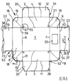
- the bottom 1 of the erecting box 50 is connected via folds 2 and 3 to the outer parts 4 and 5 of the side walls 51, 52 and via folds 6 and 7 to the outer parts 8 and 9 of the end walls 53, 54.
- the outer parts 4 and 5 are connected via folds 10 and 11 to inner parts 12 and 13 of the side walls 51, 52;
- the outer parts 8 and 9 are connected via folds 14 and 15 to inner parts 16 and 17 of the end walls 53, 54.
- the connection of the end and side walls 51, 52, 53, 54 to one another takes place by means of connecting lugs 18, which are each connected to the adjacent end of an outer part of the end and side wall to be connected via a fold 55, 56.
- Each connecting strap 18 contains a diagonal fold 19, which starts from the assigned corner 57 of the base 1 and divides the connecting strap 18 symmetrically. The folds are drawn in thinner lines than the outline.
- the inner parts 12 and 13 of the side walls 51, 52 have cutouts 20 at their outer corners.
- the outer parts 4 and 5 of the side walls 51, 52 are in the vicinity of the folds 2 and 3 and the provided with through holes 21 at the ends adjoining the connecting straps 18.
- the inner parts 16 and 17 of the end walls 53, 54 carry two locking tabs 22 on each side of their outer edge 58 via a short bending fold 24; this outer edge 58 also contains a punched-out portion 23 in its center, which serves to engage the fingers when folded after use.
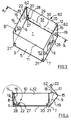
- the shape of the locking tabs 22 corresponds to the cutouts 20, in which they engage in the folded and erected state of the erecting box 50 (cf. FIG. 3).
- the wall part 9 has a punched-out viewing window 25, through which, in the erected state (FIG. 3), an inscription 26, which is printed on the wall part 17 or fastened in some other way, z. B. is visible as a label.
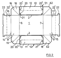
- the inner parts 12 and 13 of the side walls 51, 52 are bent inwards about the folds 10 and 11 and placed on the associated outer parts 4 and 5 and glued to them , so that the blank has the shape shown in FIG. 2.
- the cutouts 20 lie in the inner parts 12 and 13 over the regions of the outer parts 4 and 5 which contain the through holes 21.
- the inwardly folded wall parts 12, 13, 16, 17 extend only over part of the height of the wall parts 4, 5, 8, 9 extend z. B. only over half, as indicated in dashed lines and the reference numerals 20 'and 22'.
- the interlocking parts 20 'and 22' in contrast to FIG. 3, are not arranged in the region of the base part 1, but rather approximately half the height of the end or side walls 51, 52, 53, 54.
- the box is erected in such a way that the double-walled side walls 51, 52 around the folds 2 and 3 and the End walls 53, 54 are bent upwards about the folds 6 and 7 perpendicular to the bottom 1 (FIG. 4).
- the connecting flaps 18 are bent along the diagonal fold 19 towards the inside of the box (right half of FIG. 4), their two mirror-image halves abutting one another.
- the kinked connecting straps 18 are then pressed in the direction of the respective outer part 8 or 9 of the end walls, and the corresponding inner part 16 or 17 is bent inwards about the fold 14 or 15 which then lies above, so that the side walls 51, 52 are vertical are erected and the connecting straps 18 are clamped between the outer part 8 and 9 and the inner part 16 and 17, respectively.
- the side walls 51, 52 are also fixed in their vertical position.
- the locking tabs 22 they carry, preferably provided, are bent at a right angle such that they point parallel to the side walls 51, 52 into the interior of the box.
- the erection box shown in FIG. 3 is thus obtained, which is provided with the reference symbol 60 in the erected state is and has a high stability.
- the degree of prestress can be varied. If, for example, the offset m of its outer edge 62 relative to the fold 14 is chosen to be larger, as shown in broken lines in FIG. 1 is shown, the wall part 16 can be folded more easily over the wall part 8 and the clamping tab 18 clamped in between, so that the pretension is less.
- the support edge 28 on the recess 20 in the corner region of the erecting box can also be realized in that instead of the double-walled design of the side walls 51, 52 one or more support strips 29, 30 are glued to the inside of the side wall 4, 5 with the omission of the wall part 12, 13 as shown in dash-dot lines in Fig. 3.
- the locking tabs 22 are slightly bent inwards through the through holes 21 from the outside by finger pressure, so that they are moved out of the cutouts 20.
- the bias of the inner parts 16 and 17 also moves them parallel to the side walls 51, 52, so that they no longer coincide with the recesses 20 and can no longer spring back into them after being released by the finger.
- the inner parts 16 and 17 are now gripped behind in the area of the punched-outs 23 and bent outwards, so that the box 50 folded flat is obtained again as shown in FIG. 2.
- a closed box can be formed from two erection boxes 60 serving as the bottom part and the lid part according to FIG. 3, the lid part being slightly larger than the bottom part in order to be able to be put over it.
- the boxes can be used in such a way that their intended contents are transported from the supplier to the customer, that after the contents have been removed, the customer folds the boxes together and, preferably in large numbers, sends them back to the supplier, who sets them up again and can provide new content. In this way, a reusable use of the erecting boxes z. B. possible as a shoe box.
- the box can also be erected mechanically by folding up the end walls 53, 54 and pressing together the inner and outer parts 8, 9, 16, 17 until the snap connection snaps into the recess 20.
- the half of the connecting bracket 18 facing the wall part 8, 9 is preferably attached to the wall part 8, 9, preferably glued or clipped, as shown in dotted lines.
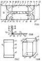
- a simplified embodiment is shown in the lower half of FIG. 5, which has no locking tabs 22 compared to the embodiment described above.
- the snap-in connection in the erected state is achieved by engaging the outer edge 27 of the wall part 16, 17 in the recess 20, which are formed here by cut edges of the wall part 13 offset by the dimension 31 relative to the fold 31. These cut edges also form the support edges 28 on which the outer edges 27 of the wall parts 16, 17 are supported in the erected state, as is shown in plan view in FIG. 6.
- the through holes 21 are no longer provided in the side walls, but in the outer wall part 8 of the end wall, as indicated by the arrow 21 '(see FIG. 5, lower half). By pushing through the through holes 21 ', the inner wall part 16 is bent so that its two outer edges 27 slide out of the recess 20 and then the erecting box can be folded flat again.
- FIG. 7 shows a packaging formed from two erection boxes described above, an intermediate piece 42 being inserted between a bottom part 40 erected according to FIG. 3 and a cover part 41.
- the intermediate piece 42 is preferably formed in one piece, which can be folded flat by folding over the four edges 43, 44, 45, 46, as is indicated in FIG. 8 by dashed lines with corresponding reference symbols 44 ', 45'.
- the intermediate piece 42 can also be in several parts, for. B. be composed of two overlapping U-shaped sections.
- end wall and side wall are not limited to the shorter or longer boundary wall of the erection box.
- recess 20 on the longer side wall 51, 52 and the wall parts 16, 17 engaging therein are preferably provided with locking tabs 22 on the shorter end wall 53, 54, the arrangement can also be reversed.
Landscapes
- Engineering & Computer Science (AREA)
- Mechanical Engineering (AREA)
- Cartons (AREA)
- Making Paper Articles (AREA)
- Passenger Equipment (AREA)
Claims (8)
- Boîte à ériger, avec des parois frontales et latérales, reliées à un fond (1) par des pliages (2, 3, 6, 7), dans laquelle :
des pattes de liaison (18) latérales, repliables vers l'intérieur, sont raccordées aux parois frontales et/ou latérales par des pliages;
les parois frontales (8, 9, 16, 17, 53, 54) sont doubles;
les pattes de liaison (18) sont chacune reliées aux extrémités (55, 56,) limitrophes les unes des autres tant de la partie de paroi extérieure (8, 9) d'une paroi frontale (53, 54) que d'une paroi latérale (4,5,51,52)et sont repliables symétriquement autour d'un pliage en diagonale (19) partant de l'angle de fond (57);
les pattes de liaison (18), à l'état érigé, sont rabattues chacune entre la partie paroi intérieure (16, 17) et extérieure (8, 9) des parois frontales (53, 54) et sont fixées au moyen de celles-ci; et
la partie de paroi intérieure (16, 17) d'une paroi frontale (53,54) étant précontrainte élastiquement par rapport à sa partie de paroi extérieure (8,9), en direction de l'intérieur de la boîte, et s'engage, avec effet d'encliquetage, tout en conservant la précontrainte agissant vers l'intérieur, dans des évidements (20) prévus sur les parois latérales (4, 5, 12, 13, 51, 52); et
chaque paroi intérieure (16, 17) d'une paroi frontale (53, 54) porte sur les arêtes, tournées chacune vers les parois latérales (51, 52) contiguës, des pattes de fixation (22) courant parallèlement aux parois latérales (51, 52) et s'engageant dans les évidements (20) réalisés en correspondance; et
les parois latérales (51, 52) sont au moins en partie doubles;
la partie de paroi intérieure (12, 13) présentant les évidements (20) destinés à recevoir la partie de paroi intérieure (16, 17) respectivement les pattes de fixation (22), caractérisée en ce que la partie extérieure (4, 5) des parois latérales (51, 52) présente, dans la zone des évidements (20), des trous d'engagement (21) destinés à la sortie par pression des pattes de fixation (22) hors des évidements (20). - Boîte à ériger selon la revendication 1, caractérisée en ce que des bandes d'appui (29, 30) sont collées sur la face intérieure des parois latérales (51, 52) pour constituer les évidements (20).
- Boîte à ériger selon la revendication 1 ou 2, caractérisée en ce que la partie de paroi intérieure (16, 17) des parois frontales (53, 54) est pourvue sur l'arête inférieure d'un estampage (23) facilitant la saisie par l'arrière.
- Boîte à ériger selon l'une des revendications 1 à 3, caractérisée en ce qu'elle est réalisée tant sous forme de partie de fond (40) que sous forme de partie de couvercle (41) d'une boîte fermée.
- Boîte à ériger selon la revendication 4, caractérisée en ce qu'entre la partie de fond (40) et la partie de couvercle (41) est insérée une pièce intermédiaire (42), pouvant être repliée à plat et réalisée en une ou plusieurs parties.
- Boîte à ériger selon l'une des revendications 1 à 5, caractérisée en ce que la partie de paroi intérieure (16, 17) de la paroi frontale (53, 54) ne prend qu'une partie de la hauteur de la partie de paroi extérieure (8, 9) et les évidements (20) prévus sur les parois latérales (51, 52) sont prévus à une hauteur identique correspondante.
- Boîte à ériger selon l'une des revendications 1 à 6, caractérisée en ce que la moitié de la patte de liaison (18), tournée vers la partie de paroi extérieure (8, 9) des parois frontales (53, 54), est fixée à la partie de paroi extérieure de préférence par collage.
- Boîte à ériger selon l'une des revendications 1 à 7, caractérisée en ce que dans au moins l'une des parties de paroi extérieure (8, 9) des parois frontales (53, 54) est découpée par estampage une fenêtre d'observation (25).
Priority Applications (1)
| Application Number | Priority Date | Filing Date | Title |
|---|---|---|---|
| DE9305614U DE9305614U1 (de) | 1992-04-08 | 1993-04-08 | Aufrichteschachtel |
Applications Claiming Priority (2)
| Application Number | Priority Date | Filing Date | Title |
|---|---|---|---|
| DE9104391U DE9104391U1 (de) | 1991-04-08 | 1991-04-08 | Aufrichteschachtel |
| DE9104391U | 1991-04-08 |
Publications (2)
| Publication Number | Publication Date |
|---|---|
| EP0508397A1 EP0508397A1 (fr) | 1992-10-14 |
| EP0508397B1 true EP0508397B1 (fr) | 1996-01-10 |
Family
ID=6866187
Family Applications (1)
| Application Number | Title | Priority Date | Filing Date |
|---|---|---|---|
| EP92106061A Expired - Lifetime EP0508397B1 (fr) | 1991-04-08 | 1992-04-08 | Boîte dépliable |
Country Status (5)
| Country | Link |
|---|---|
| US (1) | US5211330A (fr) |
| EP (1) | EP0508397B1 (fr) |
| AT (1) | ATE132824T1 (fr) |
| CA (1) | CA2065132A1 (fr) |
| DE (2) | DE9104391U1 (fr) |
Families Citing this family (29)
| Publication number | Priority date | Publication date | Assignee | Title |
|---|---|---|---|---|
| US5364015A (en) * | 1993-09-01 | 1994-11-15 | Climax Manufacturing Company | Box with simulated loose wrap |
| DE29620886U1 (de) * | 1996-11-12 | 1997-02-20 | HCH Sieger GmbH Wellpappenwerke, 50321 Brühl | Behälter |
| US6793071B2 (en) | 2001-12-18 | 2004-09-21 | World Kitchen, Inc. | Cover/pan packaging |
| US7062414B2 (en) * | 2003-07-18 | 2006-06-13 | Metrotech Corporation | Method and apparatus for digital detection of electromagnetic signal strength and signal direction in metallic pipes and cables |
| CA2601585A1 (fr) | 2005-03-17 | 2006-09-28 | Industrial Origami, Llc | Structures pliees de precision a haute resistance mecanique et resistant a la fatigue et feuille a cet effet |
| US20080098787A1 (en) | 2006-10-26 | 2008-05-01 | Industrial Origami, Inc. | Method of forming two-dimensional sheet material into three-dimensional structure |
| EP2118553A4 (fr) | 2007-02-09 | 2014-04-16 | Ind Origami Inc | Structure tridimensionnelle portant une charge |
| US20090194089A1 (en) * | 2007-12-21 | 2009-08-06 | Industrial Origami, Inc. | High-strength three-dimensional structure and method of manufacture |
| US9676511B2 (en) | 2009-09-25 | 2017-06-13 | Multi Packaging Solutions, Inc. | Foldable packaging container |
| US7959061B2 (en) | 2009-09-25 | 2011-06-14 | Multi Packaging Solutions, Inc. | Folded pot cover |
| US8550331B2 (en) | 2011-05-20 | 2013-10-08 | Multi Packaging Solutions, Inc. | Foldable container and attachments |
| US8936164B2 (en) | 2012-07-06 | 2015-01-20 | Industrial Origami, Inc. | Solar panel rack |
| USD675107S1 (en) | 2012-07-20 | 2013-01-29 | Multi Packaging Solutions, Inc. | Wrap packaging |
| USD676337S1 (en) | 2012-07-20 | 2013-02-19 | Multi Packaging Solutions, Inc. | Wrap packaging |
| WO2016073676A1 (fr) * | 2014-11-07 | 2016-05-12 | Graphic Packaging International, Inc. | Barquette pour produit alimentaire |
| US10232973B2 (en) | 2014-11-07 | 2019-03-19 | Graphic Packaging International, Llc | Tray for holding a food product |
| US10208961B2 (en) | 2015-07-16 | 2019-02-19 | Pennant Moldings, Inc. | One-piece sheet-metal structure formed with clench locked corners |
| CN208915652U (zh) * | 2018-08-13 | 2019-05-31 | 厦门市金玺彩印有限公司 | 免折快速成型盒体 |
| JP2022508228A (ja) * | 2018-11-26 | 2022-01-19 | ガンマ-ウォプラ エス アー | 折り畳み式容器 |
| WO2022098865A1 (fr) | 2020-11-06 | 2022-05-12 | Graphic Packaging International, Llc | Plateau pour produits alimentaires |
| USD1042120S1 (en) | 2021-05-27 | 2024-09-17 | Graphic Packaging International, Llc | Tray |
| USD1042117S1 (en) | 2021-05-27 | 2024-09-17 | Graphic Packaging International, Llc | Tray |
| USD1042121S1 (en) | 2021-05-27 | 2024-09-17 | Graphic Packaging International, Llc | Tray |
| USD1042122S1 (en) | 2021-05-27 | 2024-09-17 | Graphic Packaging International, Llc | Tray |
| USD1044494S1 (en) | 2021-05-27 | 2024-10-01 | Graphic Packaging International, Llc | Tray |
| USD1042118S1 (en) | 2021-05-27 | 2024-09-17 | Graphic Packaging International, Llc | Tray |
| USD1062459S1 (en) | 2021-05-27 | 2025-02-18 | Graphic Packaging International, Llc | Tray |
| USD1042119S1 (en) | 2021-05-27 | 2024-09-17 | Graphic Pachaging International, LLC | Tray |
| USD1042116S1 (en) | 2021-05-27 | 2024-09-17 | Graphic Packaging International, Llc | Carton |
Family Cites Families (19)
| Publication number | Priority date | Publication date | Assignee | Title |
|---|---|---|---|---|
| US695205A (en) * | 1901-12-20 | 1902-03-11 | J W Sefton Mfg Company | Paper box. |
| US1144746A (en) * | 1915-02-05 | 1915-06-29 | Stecher Lithographic Company | Folding box. |
| US1778462A (en) * | 1928-01-16 | 1930-10-14 | Ralph C C Nourse | Foldable box |
| US1755694A (en) * | 1928-04-09 | 1930-04-22 | Brown & Bailey Company | Packing and display box |
| US1726682A (en) * | 1928-09-15 | 1929-09-03 | Howard S Scholes | Foldable box |
| US2143308A (en) * | 1934-03-29 | 1939-01-10 | Flach Paul | Folded box |
| US2179421A (en) * | 1938-05-27 | 1939-11-07 | John J Murray | Paper box, carton, or tray |
| US2453614A (en) * | 1946-05-15 | 1948-11-09 | Belsinger Inc | Easy packing container |
| US2702663A (en) * | 1952-04-16 | 1955-02-22 | Empire Box Corp | Nested carton blank |
| US2859906A (en) * | 1955-03-07 | 1958-11-11 | Waldorf Paper Prod Co | Telescoping carton |
| US2915235A (en) * | 1956-10-29 | 1959-12-01 | Swift & Co | Container for frozen foods |
| GB959208A (en) * | 1961-01-20 | 1964-05-27 | Smith & Young Ltd | Improvements in or relating to box-like envelopes and blanks therefor |
| US3137434A (en) * | 1961-04-19 | 1964-06-16 | Weyerhaeuser Co | Carton |
| US3910483A (en) * | 1974-11-07 | 1975-10-07 | Int Paper Co | Two-piece, paperboard container construction |
| US4037777A (en) * | 1976-06-15 | 1977-07-26 | Westvaco Corporation | Handhole closure for containers |
| US4055293A (en) * | 1977-02-04 | 1977-10-25 | Container Corporation Of America | Tray with reinforced walls |
| US4127228A (en) * | 1977-08-04 | 1978-11-28 | Willamette Industries, Inc. | Asparagus box |
| DE3302972A1 (de) * | 1982-03-13 | 1983-09-22 | Allgäuer Holzspanschachtelfabrik und Kartonagenwerk Albert Frey, 8949 Dirlewang | Stapelbare aufrichteschachtel |
| US4762226A (en) * | 1983-10-12 | 1988-08-09 | White Consolidated Industries, Inc. | Shipping container for major appliances |
-
1991
- 1991-04-08 DE DE9104391U patent/DE9104391U1/de not_active Expired - Lifetime
-
1992
- 1992-04-03 CA CA002065132A patent/CA2065132A1/fr not_active Abandoned
- 1992-04-06 US US07/864,294 patent/US5211330A/en not_active Expired - Fee Related
- 1992-04-08 EP EP92106061A patent/EP0508397B1/fr not_active Expired - Lifetime
- 1992-04-08 AT AT92106061T patent/ATE132824T1/de not_active IP Right Cessation
- 1992-04-08 DE DE59204970T patent/DE59204970D1/de not_active Expired - Fee Related
Also Published As
| Publication number | Publication date |
|---|---|
| EP0508397A1 (fr) | 1992-10-14 |
| DE59204970D1 (de) | 1996-02-22 |
| DE9104391U1 (de) | 1991-08-01 |
| ATE132824T1 (de) | 1996-01-15 |
| CA2065132A1 (fr) | 1992-10-09 |
| US5211330A (en) | 1993-05-18 |
Similar Documents
| Publication | Publication Date | Title |
|---|---|---|
| EP0508397B1 (fr) | Boîte dépliable | |
| DE69702930T2 (de) | Kartonschachtel mit zentrierlaschen und zuschnitt für ihre herstellung | |
| DE2842988A1 (de) | Schutzverpackung | |
| DE2643720C2 (de) | Stapelbarer Transportbehälter | |
| EP0491399B1 (fr) | Boîte avec couvercle perforé | |
| DE69314588T2 (de) | Kartonschale | |
| DE68920872T2 (de) | Verpackungsbehälter. | |
| DE4204075C2 (de) | Transportverpackung | |
| DE19709969C2 (de) | Verpackung für Bilderhalter, insbesondere rahmenlose Bilderhalter | |
| EP1341698B1 (fr) | Boite pliante | |
| DE2914882A1 (de) | Faltbehaelter | |
| DE7536839U (de) | Aufrichteschachtel | |
| DE9012424U1 (de) | Tray-Einsatz mit Umkarton | |
| DE2941230A1 (de) | Steige | |
| CH591369A5 (en) | Corner reinforced folded cardboard box - has end walls doubled over and inclined inwards to form stacking supports at corners (OE 15.6.77) | |
| DE9305614U1 (de) | Aufrichteschachtel | |
| DE202024102489U1 (de) | Kartonzuschnitt zur Herstellung einer Gebindeverstärkung und Gebindeverstärkung | |
| DE9216430U1 (de) | Aus einem Zuschnitt aus Verpackungskarton aufgerichtete stapelbare Verpackung | |
| DE9205177U1 (de) | Obst- oder Gemüsekiste | |
| DE29820547U1 (de) | Vielseitig verwendbare Faltschachtel | |
| EP1522498A1 (fr) | Conteneur pour le transport et le stockage | |
| DE1134330B (de) | Faltschachtel, insbesondere fuer Flaschenreihen | |
| DE9420580U1 (de) | Einstückiger Karton-Zuschnitt für eine Verpackung sowie hieraus hergestellte Verpackung | |
| DE9312950U1 (de) | Faltschachtel | |
| DE20112752U1 (de) | Verpackungseinheit mit achteckigem Querschnitt |
Legal Events
| Date | Code | Title | Description |
|---|---|---|---|
| PUAI | Public reference made under article 153(3) epc to a published international application that has entered the european phase |
Free format text: ORIGINAL CODE: 0009012 |
|
| AK | Designated contracting states |
Kind code of ref document: A1 Designated state(s): AT BE CH DE DK ES FR GB IT LI LU NL SE |
|
| 17P | Request for examination filed |
Effective date: 19930409 |
|
| 17Q | First examination report despatched |
Effective date: 19940715 |
|
| GRAA | (expected) grant |
Free format text: ORIGINAL CODE: 0009210 |
|
| AK | Designated contracting states |
Kind code of ref document: B1 Designated state(s): AT BE CH DE DK ES FR GB IT LI LU NL SE |
|
| PG25 | Lapsed in a contracting state [announced via postgrant information from national office to epo] |
Ref country code: IT Free format text: LAPSE BECAUSE OF FAILURE TO SUBMIT A TRANSLATION OF THE DESCRIPTION OR TO PAY THE FEE WITHIN THE PRE;WARNING: LAPSES OF ITALIAN PATENTS WITH EFFECTIVE DATE BEFORE 2007 MAY HAVE OCCURRED AT ANY TIME BEFORE 2007. THE CORRECT EFFECTIVE DATE MAY BE DIFFERENT FROM THE ONE RECORDED.SCRIBED TIME-LIMIT Effective date: 19960110 Ref country code: ES Free format text: THE PATENT HAS BEEN ANNULLED BY A DECISION OF A NATIONAL AUTHORITY Effective date: 19960110 Ref country code: FR Effective date: 19960110 Ref country code: DK Effective date: 19960110 Ref country code: BE Effective date: 19960110 Ref country code: GB Effective date: 19960110 Ref country code: NL Free format text: LAPSE BECAUSE OF FAILURE TO SUBMIT A TRANSLATION OF THE DESCRIPTION OR TO PAY THE FEE WITHIN THE PRESCRIBED TIME-LIMIT Effective date: 19960110 |
|
| REF | Corresponds to: |
Ref document number: 132824 Country of ref document: AT Date of ref document: 19960115 Kind code of ref document: T |
|
| REF | Corresponds to: |
Ref document number: 59204970 Country of ref document: DE Date of ref document: 19960222 |
|
| PG25 | Lapsed in a contracting state [announced via postgrant information from national office to epo] |
Ref country code: AT Effective date: 19960408 |
|
| PG25 | Lapsed in a contracting state [announced via postgrant information from national office to epo] |
Ref country code: SE Effective date: 19960410 |
|
| PG25 | Lapsed in a contracting state [announced via postgrant information from national office to epo] |
Ref country code: LI Effective date: 19960430 Ref country code: LU Free format text: LAPSE BECAUSE OF NON-PAYMENT OF DUE FEES Effective date: 19960430 Ref country code: CH Effective date: 19960430 |
|
| NLV1 | Nl: lapsed or annulled due to failure to fulfill the requirements of art. 29p and 29m of the patents act | ||
| EN | Fr: translation not filed | ||
| GBV | Gb: ep patent (uk) treated as always having been void in accordance with gb section 77(7)/1977 [no translation filed] |
Effective date: 19960110 |
|
| PLBE | No opposition filed within time limit |
Free format text: ORIGINAL CODE: 0009261 |
|
| STAA | Information on the status of an ep patent application or granted ep patent |
Free format text: STATUS: NO OPPOSITION FILED WITHIN TIME LIMIT |
|
| REG | Reference to a national code |
Ref country code: CH Ref legal event code: PL |
|
| PG25 | Lapsed in a contracting state [announced via postgrant information from national office to epo] |
Ref country code: DE Effective date: 19970101 |
|
| 26N | No opposition filed |