EP0508397B1 - Collapsible box - Google Patents
Collapsible box Download PDFInfo
- Publication number
- EP0508397B1 EP0508397B1 EP92106061A EP92106061A EP0508397B1 EP 0508397 B1 EP0508397 B1 EP 0508397B1 EP 92106061 A EP92106061 A EP 92106061A EP 92106061 A EP92106061 A EP 92106061A EP 0508397 B1 EP0508397 B1 EP 0508397B1
- Authority
- EP
- European Patent Office
- Prior art keywords
- side walls
- box
- wall
- wall portion
- walls
- Prior art date
- Legal status (The legal status is an assumption and is not a legal conclusion. Google has not performed a legal analysis and makes no representation as to the accuracy of the status listed.)
- Expired - Lifetime
Links
- 238000010276 construction Methods 0.000 abstract 1
- 239000000463 material Substances 0.000 description 4
- 238000005452 bending Methods 0.000 description 3
- 210000002105 tongue Anatomy 0.000 description 3
- 230000001771 impaired effect Effects 0.000 description 2
- 238000004806 packaging method and process Methods 0.000 description 2
- 238000003825 pressing Methods 0.000 description 2
- 238000011161 development Methods 0.000 description 1
- 230000018109 developmental process Effects 0.000 description 1
- 230000000694 effects Effects 0.000 description 1
- 210000004905 finger nail Anatomy 0.000 description 1
- 238000004519 manufacturing process Methods 0.000 description 1
- 238000000034 method Methods 0.000 description 1
Images
Classifications
-
- B—PERFORMING OPERATIONS; TRANSPORTING
- B65—CONVEYING; PACKING; STORING; HANDLING THIN OR FILAMENTARY MATERIAL
- B65D—CONTAINERS FOR STORAGE OR TRANSPORT OF ARTICLES OR MATERIALS, e.g. BAGS, BARRELS, BOTTLES, BOXES, CANS, CARTONS, CRATES, DRUMS, JARS, TANKS, HOPPERS, FORWARDING CONTAINERS; ACCESSORIES, CLOSURES, OR FITTINGS THEREFOR; PACKAGING ELEMENTS; PACKAGES
- B65D5/00—Rigid or semi-rigid containers of polygonal cross-section, e.g. boxes, cartons or trays, formed by folding or erecting one or more blanks made of paper
- B65D5/20—Rigid or semi-rigid containers of polygonal cross-section, e.g. boxes, cartons or trays, formed by folding or erecting one or more blanks made of paper by folding-up portions connected to a central panel from all sides to form a container body, e.g. of tray-like form
- B65D5/24—Rigid or semi-rigid containers of polygonal cross-section, e.g. boxes, cartons or trays, formed by folding or erecting one or more blanks made of paper by folding-up portions connected to a central panel from all sides to form a container body, e.g. of tray-like form with adjacent sides interconnected by gusset folds
- B65D5/248—Rigid or semi-rigid containers of polygonal cross-section, e.g. boxes, cartons or trays, formed by folding or erecting one or more blanks made of paper by folding-up portions connected to a central panel from all sides to form a container body, e.g. of tray-like form with adjacent sides interconnected by gusset folds and at least one side being extended and doubled-over to enclose the adjacent gusset flaps
Definitions
- the invention relates to an erection box according to the preamble of claim 1.
- An erection box is known for example from DE 33 02 972 C2. This is designed as an open, stackable crate, in which tongues protruding from the end of the side walls engage in corresponding recesses at the end of the end walls and thus hold the box in an erect state.
- the known erection box is therefore unsuitable for repeated use if, for transport reasons, it requires folding and re-erecting the box.
- the tongues are also subjected to additional pressure when pressure is exerted against the side walls, which can also lead to a rapid loss of rigidity and thus the stability of the box.
- a righting box according to the preamble features of claim 1 is known from GB-A-965 590, the end walls of the righting box being double-walled and being symmetrically foldable around a diagonal fold starting from the bottom corner.
- the side walls are also designed in duplicate, with recesses being provided in the area of the floor corners, into which locking tabs integrally formed on the outer corner of the cut of the end walls engage, so that a relatively stable erecting box results.
- the invention has for its object to provide an erecting box that can be folded and re-erected in many ways without affecting its stability, and the folding and re-erection can also be carried out easily by inexperienced persons.
- the proposed design with the features of claim 1 gives a dimensionally stable box, in which the recesses or recesses are only exposed to the load caused by the slight prestressing of the inner wall part of the end walls. External loads, however, do not act on the recesses and wall parts engaging therein, so that they remain dimensionally stable and their function is not impaired.
- locking tabs are provided in the corner area of the inner wall part of the end walls, which snap into correspondingly shaped recesses on the side walls. The locking tab is not subjected to bending, but only to pressure in the direction of the material, which results in greater stability due to the higher resilience of cardboard or cardboard in this direction of stress.
- the side walls are also double-walled, the inner wall part containing the recesses for receiving the inner wall part or the locking tabs, so that they fold and rest on the outer wall part of the side walls, and are thereby securely fixed in position.
- the outer wall part of the side walls now contains through-holes in the area of the cutouts for pressing the locking tabs out of the cutouts, as a result of which the collapsing of the erected box is very simplified. If a large number of collapsed boxes are stacked on top of one another, bolts, rods, wires, strips or the like clamping means can be passed through the through holes, so that a compact, easily transportable package is obtained.
- the erection box Since the erection box has an opening that is limited only by the narrow upper edges of the side and end walls, it can be used both as a bottom part and on the other hand as a lid part for a closed box.
- the bottom 1 of the erecting box 50 is connected via folds 2 and 3 to the outer parts 4 and 5 of the side walls 51, 52 and via folds 6 and 7 to the outer parts 8 and 9 of the end walls 53, 54.
- the outer parts 4 and 5 are connected via folds 10 and 11 to inner parts 12 and 13 of the side walls 51, 52;
- the outer parts 8 and 9 are connected via folds 14 and 15 to inner parts 16 and 17 of the end walls 53, 54.
- the connection of the end and side walls 51, 52, 53, 54 to one another takes place by means of connecting lugs 18, which are each connected to the adjacent end of an outer part of the end and side wall to be connected via a fold 55, 56.
- Each connecting strap 18 contains a diagonal fold 19, which starts from the assigned corner 57 of the base 1 and divides the connecting strap 18 symmetrically. The folds are drawn in thinner lines than the outline.
- the inner parts 12 and 13 of the side walls 51, 52 have cutouts 20 at their outer corners.
- the outer parts 4 and 5 of the side walls 51, 52 are in the vicinity of the folds 2 and 3 and the provided with through holes 21 at the ends adjoining the connecting straps 18.
- the inner parts 16 and 17 of the end walls 53, 54 carry two locking tabs 22 on each side of their outer edge 58 via a short bending fold 24; this outer edge 58 also contains a punched-out portion 23 in its center, which serves to engage the fingers when folded after use.
- the shape of the locking tabs 22 corresponds to the cutouts 20, in which they engage in the folded and erected state of the erecting box 50 (cf. FIG. 3).
- the wall part 9 has a punched-out viewing window 25, through which, in the erected state (FIG. 3), an inscription 26, which is printed on the wall part 17 or fastened in some other way, z. B. is visible as a label.
- the inner parts 12 and 13 of the side walls 51, 52 are bent inwards about the folds 10 and 11 and placed on the associated outer parts 4 and 5 and glued to them , so that the blank has the shape shown in FIG. 2.
- the cutouts 20 lie in the inner parts 12 and 13 over the regions of the outer parts 4 and 5 which contain the through holes 21.
- the inwardly folded wall parts 12, 13, 16, 17 extend only over part of the height of the wall parts 4, 5, 8, 9 extend z. B. only over half, as indicated in dashed lines and the reference numerals 20 'and 22'.
- the interlocking parts 20 'and 22' in contrast to FIG. 3, are not arranged in the region of the base part 1, but rather approximately half the height of the end or side walls 51, 52, 53, 54.
- the box is erected in such a way that the double-walled side walls 51, 52 around the folds 2 and 3 and the End walls 53, 54 are bent upwards about the folds 6 and 7 perpendicular to the bottom 1 (FIG. 4).
- the connecting flaps 18 are bent along the diagonal fold 19 towards the inside of the box (right half of FIG. 4), their two mirror-image halves abutting one another.
- the kinked connecting straps 18 are then pressed in the direction of the respective outer part 8 or 9 of the end walls, and the corresponding inner part 16 or 17 is bent inwards about the fold 14 or 15 which then lies above, so that the side walls 51, 52 are vertical are erected and the connecting straps 18 are clamped between the outer part 8 and 9 and the inner part 16 and 17, respectively.
- the side walls 51, 52 are also fixed in their vertical position.
- the locking tabs 22 they carry, preferably provided, are bent at a right angle such that they point parallel to the side walls 51, 52 into the interior of the box.
- the erection box shown in FIG. 3 is thus obtained, which is provided with the reference symbol 60 in the erected state is and has a high stability.
- the degree of prestress can be varied. If, for example, the offset m of its outer edge 62 relative to the fold 14 is chosen to be larger, as shown in broken lines in FIG. 1 is shown, the wall part 16 can be folded more easily over the wall part 8 and the clamping tab 18 clamped in between, so that the pretension is less.
- the support edge 28 on the recess 20 in the corner region of the erecting box can also be realized in that instead of the double-walled design of the side walls 51, 52 one or more support strips 29, 30 are glued to the inside of the side wall 4, 5 with the omission of the wall part 12, 13 as shown in dash-dot lines in Fig. 3.
- the locking tabs 22 are slightly bent inwards through the through holes 21 from the outside by finger pressure, so that they are moved out of the cutouts 20.
- the bias of the inner parts 16 and 17 also moves them parallel to the side walls 51, 52, so that they no longer coincide with the recesses 20 and can no longer spring back into them after being released by the finger.
- the inner parts 16 and 17 are now gripped behind in the area of the punched-outs 23 and bent outwards, so that the box 50 folded flat is obtained again as shown in FIG. 2.
- a closed box can be formed from two erection boxes 60 serving as the bottom part and the lid part according to FIG. 3, the lid part being slightly larger than the bottom part in order to be able to be put over it.
- the boxes can be used in such a way that their intended contents are transported from the supplier to the customer, that after the contents have been removed, the customer folds the boxes together and, preferably in large numbers, sends them back to the supplier, who sets them up again and can provide new content. In this way, a reusable use of the erecting boxes z. B. possible as a shoe box.
- the box can also be erected mechanically by folding up the end walls 53, 54 and pressing together the inner and outer parts 8, 9, 16, 17 until the snap connection snaps into the recess 20.
- the half of the connecting bracket 18 facing the wall part 8, 9 is preferably attached to the wall part 8, 9, preferably glued or clipped, as shown in dotted lines.
- a simplified embodiment is shown in the lower half of FIG. 5, which has no locking tabs 22 compared to the embodiment described above.
- the snap-in connection in the erected state is achieved by engaging the outer edge 27 of the wall part 16, 17 in the recess 20, which are formed here by cut edges of the wall part 13 offset by the dimension 31 relative to the fold 31. These cut edges also form the support edges 28 on which the outer edges 27 of the wall parts 16, 17 are supported in the erected state, as is shown in plan view in FIG. 6.
- the through holes 21 are no longer provided in the side walls, but in the outer wall part 8 of the end wall, as indicated by the arrow 21 '(see FIG. 5, lower half). By pushing through the through holes 21 ', the inner wall part 16 is bent so that its two outer edges 27 slide out of the recess 20 and then the erecting box can be folded flat again.
- FIG. 7 shows a packaging formed from two erection boxes described above, an intermediate piece 42 being inserted between a bottom part 40 erected according to FIG. 3 and a cover part 41.
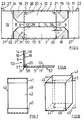
- the intermediate piece 42 is preferably formed in one piece, which can be folded flat by folding over the four edges 43, 44, 45, 46, as is indicated in FIG. 8 by dashed lines with corresponding reference symbols 44 ', 45'.
- the intermediate piece 42 can also be in several parts, for. B. be composed of two overlapping U-shaped sections.
- end wall and side wall are not limited to the shorter or longer boundary wall of the erection box.
- recess 20 on the longer side wall 51, 52 and the wall parts 16, 17 engaging therein are preferably provided with locking tabs 22 on the shorter end wall 53, 54, the arrangement can also be reversed.
Landscapes
- Engineering & Computer Science (AREA)
- Mechanical Engineering (AREA)
- Cartons (AREA)
- Making Paper Articles (AREA)
- Passenger Equipment (AREA)
Abstract
Description
Die Erfindung betrifft eine Aufrichteschachtel nach dem Oberbegriff des Anspruchs 1.The invention relates to an erection box according to the preamble of
Eine Aufrichteschachtel ist beispielsweise aus der DE 33 02 972 C2 bekannt. Diese ist als offene, stapelbare Steige ausgebildet, bei der vom Ende der Seitenwände vorstehende Zungen in entsprechende Aussparungen am Ende der Stirnwände greifen und so die Schachtel im aufgerichteten Zustand halten. Bei mehrmaligem Aufrichten und Zusammenlegen der Schachtel verlieren die Zungen jedoch ihre Steifigkeit, so daß die Stabilität der Schachtel beeinträchtigt ist. Die bekannte Aufrichteschachtel ist daher für einen mehrmaligen Gebrauch ungeeignet, wenn dieser aus Transportgründen jeweils ein Zusammenlegen und Wiederaufrichten der Schachtel erfordert. Auch werden die Zungen bei einem gegen die Seitenwände wirkenden Druck zusätzlich belastet, was ebenfalls zu einem raschen Verlust der Steifigkeit und damit der Stabilität der Schachtel führen kann.An erection box is known for example from DE 33 02 972 C2. This is designed as an open, stackable crate, in which tongues protruding from the end of the side walls engage in corresponding recesses at the end of the end walls and thus hold the box in an erect state. However, when the box is erected and folded several times, the tongues lose their rigidity, so that the stability of the box is impaired. The known erection box is therefore unsuitable for repeated use if, for transport reasons, it requires folding and re-erecting the box. The tongues are also subjected to additional pressure when pressure is exerted against the side walls, which can also lead to a rapid loss of rigidity and thus the stability of the box.
Eine Aufrichteschachtel gemäß den oberbegrifflichen Merkmalen des Anspruches 1 ist aus der GB-A-965 590 bekannt, wobei die Stirnwände der Aufrichteschachtel doppelwandig ausgebildet sind und um einen von der Bodenecke ausgehenden Diagonalfalz symmetrisch faltbar sind. Auch die Seitenwände sind hierbei doppelt ausgeführt, wobei im Bereich der Bodenecken Aussparungen vorgesehen sind, in die an der äußeren Ecke des Zuschnittes der Stirnwände einstückig angeformte Arretierungslaschen eingreifen, so daß sich eine relativ stabile Aufrichteschachtel ergibt.A righting box according to the preamble features of
Obwohl hiermit ein relativ rasches Aufrichten des Zuschnittes der Aufrichteschachtel ermöglicht wird, gestaltet sich jedoch das Wieder-Zusammenlegen der Aufrichteschachtel als relativ kompliziert, da die insgesamt vier Arretierungslaschen im Eckbereich der Aufrichteschachtel auf aufwendige Weise mit dem Fingernagel oder einem Werkzeug aus dem federnden Eingriff mit der Aussparung gelöst werden müssen.Although this enables a relatively quick erection of the blank of the erecting box, the reassembly of the erecting box is relatively complicated, since the four locking tabs in the corner region of the erecting box are laboriously removed with a fingernail or a tool from the resilient engagement with the Recess must be solved.
Demzufolge liegt der Erfindung die Aufgabe zugrunde, eine Aufrichteschachtel zu schaffen, die vielfach zusammenlegbar und wiederaufrichtbar ist, ohne daß ihre Stabilität beeinträchtigt wird, wobei das Zusammenlegen und Wiederaufrichten auch von ungeübten Personen auf einfache Weise vorgenommen werden kann.Accordingly, the invention has for its object to provide an erecting box that can be folded and re-erected in many ways without affecting its stability, and the folding and re-erection can also be carried out easily by inexperienced persons.
Diese Aufgabe wird erfindungsgemäß gelöst durch eine Aufrichteschachtel mit den Merkmalen des Anspruchs 1.This object is achieved according to the invention by an erection box with the features of
Durch die vorgeschlagene Ausbildung mit den Merkmalen des Anspruchs 1 erhält man eine formstabile Schachtel, bei der die Aussparungen oder Ausnehmungen nur der Belastung durch die geringe Vorspannung des inneren Wandteils der Stirnwände ausgesetzt sind. Äußere Belastungen dagegen wirken nicht auf die Aussparungen und darin eingreifenden Wandteile ein, so daß sie formstabil bleiben und in ihrer Funktion nicht beeinträchtigt werden. Dabei sind im Eckbereich des inneren Wandteils der Stirnwände Arretierungslaschen vorgesehen, die in entsprechend flächengleich ausgebildete Aussparungen an den Seitenwänden einrasten. Dabei ist die Arretierungslasche nicht auf Biegung, sondern in Materialrichtung lediglich auf Druck belastet, wodurch sich aufgrund der höheren Belastbarkeit von Pappe oder Karton in dieser Beanspruchungsrichtung eine höhere Stabilität ergibt. Die Seitenwände sind dabei ebenfalls doppelwandig ausgebildet, wobei der innere Wandteil die Aussparungen zur Aufnahme des inneren Wandteils bzw. der Arretierungslaschen enthält, so daß diese am äußeren Wandteil der Seitenwände einklappen und anliegen, und dadurch sicher in ihrer Lage fixiert sind.The proposed design with the features of
Der äußere Wandteil der Seitenwände enthält nunmehr im Bereich der Aussparungen Durchgriffslöcher für das Herausdrücken der Arretierungslaschen aus den Aussparungen, wodurch das Zusammenlegen der aufgerichteten Schachtel sehr vereinfacht wird. Wenn eine größere Anzahl von zusammengelegten Schachteln übereinandergestapelt wird, können Schraubbolzen, Stangen, Drähte, Bänder oder dergleichen Spannmittel durch die Durchgriffslöcher geführt werden, so daß man ein kompaktes, leicht transportfähiges Paket erhält.The outer wall part of the side walls now contains through-holes in the area of the cutouts for pressing the locking tabs out of the cutouts, as a result of which the collapsing of the erected box is very simplified. If a large number of collapsed boxes are stacked on top of one another, bolts, rods, wires, strips or the like clamping means can be passed through the through holes, so that a compact, easily transportable package is obtained.
Da die Aufrichteschachtel eine Öffnung besitzt, die nur durch die schmalen Oberkanten der Seiten- und Stirnwände begrenzt ist, kann sie sowohl einerseits als Bodenteil als auch andererseits als Deckelteil für eine geschlossene Schachtel verwendet werden.Since the erection box has an opening that is limited only by the narrow upper edges of the side and end walls, it can be used both as a bottom part and on the other hand as a lid part for a closed box.
Weitere vorteilhafte Weiterbildungen der Aufrichteschachtel ergeben sich aus den Unteransprüchen.Further advantageous developments of the erecting box result from the subclaims.
Die Erfindung wird im folgenden anhand von in den Figuren dargestellten Ausführungsbeispielen näher erläutert. Es zeigen:
- Fig. 1
- den ausgestanzten Zuschnitt einer Aufrichteschachtel in der Draufsicht;
- Fig. 2
- die Aufrichteschachtel gemäß Fig. 1 in teilweise zusammengelegten Zustand in der Draufsicht;
- Fig. 3
- die Aufrichteschachtel im aufgerichteten Zustand in perspektivischer Darstellung;
- Fig. 4
- einen Längsschnitt entlang der Linie A-A durch die Aufrichteschachtel zur Verdeutlichung des Aufrichtevorgangs;
- Fig. 5
- eine abgewandelte Ausführungsform der Aufrichteschachtel;
- Fig. 6
- eine Draufsicht (gemäß Pfeil B in Fig. 3) auf den Eckbereich einer aufgestellten Aufrichteschachtel gemäß Fig. 5;
- Fig. 7
- eine Großverpackung mit Zwischenstück in Seitenansicht;
- Fig. 8
- das Zwischenstück gemäß Fig. 7 in Perspektivansicht.
- Fig. 1
- the punched blank of an erection box in plan view;
- Fig. 2
- the erection box of Figure 1 in a partially folded state in plan view.
- Fig. 3
- the erection box in the erected state in a perspective view;
- Fig. 4
- a longitudinal section along the line AA through the erection box to illustrate the erection process;
- Fig. 5
- a modified embodiment of the erection box;
- Fig. 6
- a plan view (according to arrow B in FIG. 3) of the corner area of an erected erection box according to FIG. 5;
- Fig. 7
- a large packaging with intermediate piece in side view;
- Fig. 8
- 7 in perspective view.
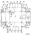
Der Boden 1 der Aufrichteschachtel 50 ist über Falze 2 und 3 mit den Außenteilen 4 und 5 der Seitenwände 51, 52 sowie über Falze 6 und 7 mit den Außenteilen 8 und 9 der Stirnwände 53, 54 verbunden. Die Außenteile 4 und 5 sind über Falze 10 und 11 mit Innenteilen 12 und 13 der Seitenwände 51, 52 verbunden; entsprechend sind die Außenteile 8 und 9 über Falze 14 und 15 mit Innenteilen 16 und 17 der Stirnwände 53, 54 verbunden. Die Verbindung der Stirn- und Seitenwände 51, 52, 53, 54 untereinander erfolgt durch Verbindungslaschen 18, die jeweils mit dem angrenzenden Ende eines Außenteils der zu verbindenen Stirn- und Seitenwand über einen Falz 55, 56 verbunden sind. Jede Verbindungslasche 18 enthält einen Diagonalfalz 19, der von der zugeordneten Ecke 57 des Bodens 1 ausgeht und die Verbindungslasche 18 symmetrisch teilt. Die Falze sind gegenüber den Umrißlinien in dünneren Linien gezeichnet.The
Die Innenteile 12 und 13 der Seitenwände 51, 52 weisen an ihren äußeren Ecken Aussparungen 20 auf. Die Außenteile 4 und 5 der Seitenwände 51, 52 sind in der Nähe der Falze 2 und 3 sowie der an die Verbindungslaschen 18 angrenzenden Enden mit Durchgriffslöchern 21 versehen. Weiterhin tragen die Innenteile 16 und 17 der Stirnwände 53, 54 zu beiden Seiten ihrer Außenkante 58 über einen kurzen Biegefalz 24 jeweils zwei Arretierungslaschen 22; diese Außenkante 58 enthält in ihrer Mitte außerdem eine Ausstanzung 23, die beim Zusammenlegen nach Gebrauch zum Eingriff der Finger dient. Die Arretierungslaschen 22 entsprechen in ihrer Form den Aussparungen 20, in die sie in zusammengefaltetem und aufgerichtetem Zustand der Aufrichteschachtel 50 eingreifen (vgl. Fig. 3).The
Der Wandteil 9 weist in bevorzugter Ausführung ein ausgestanztes Sichtfenster 25 auf, durch das in aufgerichtetem Zustand (Fig. 3) eine auf dem Wandteil 17 aufgedruckte oder auf sonstige Weise befestigte Beschriftung 26 z. B. als Etikett sichtbar ist.In a preferred embodiment, the
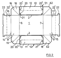
Der vorbeschriebene Zuschnitt der Aufrichteschachtel 50 gemäß Fig. 1 wird in der Weise weiterverarbeitet, daß die Innenteile 12 und 13 der Seitenwände 51, 52 um die Falze 10 und 11 nach innen gebogen und auf die zugehörigen Außenteile 4 und 5 gelegt und mit diesen verklebt werden, so daß der Zuschnitt die Form gemäß Fig. 2 aufweist. Hierbei liegen die Aussparungen 20 in den Innenteilen 12 und 13 über den die Durchgriffslöcher 21 enthaltenden Bereichen der Außenteile 4 und 5.1 is further processed in such a way that the
Um Material (z. B. Pappe, Karton oder Kunststoff) für die Herstellung der Aufrichteschachtel 50 zu sparen, genügt es auch, daß sich die nach innen geklappten Wandteile 12, 13, 16, 17 nur über einen Teil der Höhe der Wandteile 4, 5, 8, 9 erstrecken z. B. nur über die Hälfte, wie dies in Strichlinien und den Bezugszeichen 20' und 22' angedeutet ist. In diesem Fall sind im aufgerichteten Zustand der Schachtel die ineinandergreifenden Teile 20' und 22' im Gegensatz zu Fig. 3 nicht im Bereich des Bodenteils 1 angeordnet, sondern etwa in halber Höhe der Stirn- bzw. Seitenwände 51, 52, 53, 54.In order to save material (e.g. cardboard, cardboard or plastic) for the production of the erecting
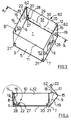
Das Aufrichten der Schachtel erfolgt derart, daß die doppelwandigen Seitenwände 51, 52 um die Falze 2 und 3 und die Stirnwände 53, 54 um die Falze 6 und 7 senkrecht zum Boden 1 nach oben gebogen werden (Fig. 4). Die Verbindungslaschen 18 werden entlang der Diagonalfalze 19 zum Schachtelinneren hin eingeknickt (rechte Hälfte von Fig. 4), wobei sich ihre beiden spiegelbildlichen Hälften aneinanderlegen. Die geknickten Verbindungslaschen 18 werden dann in Richtung des jeweiligen Außenteils 8 bzw. 9 der Stirnwände angedrückt, und der entsprechende Innenteil 16 bzw. 17 wird um den dann oben liegenden Falz 14 bzw. 15 nach innen gebogen, so daß die Seitenwände 51, 52 senkrecht aufgerichtet werden und die Verbindungslaschen 18 jeweils zwischen dem Außenteil 8 bzw. 9 und dem Innenteil 16 bzw. 17 eingeklemmt werden. Hierdurch sind auch die Seitenwände 51, 52 in ihrer senkrechten Position fixiert. Beim Umbiegen der Innenteile 16 und 17 werden auch die von ihnen getragenen, bevorzugt vorgesehenen Arretierungslaschen 22 rechtwinklig umgebogen, derart, daß sie parallel zu den Seitenwänden 51, 52 verlaufend in das Schachtelinnere weisen. Wenn die Innenteile 16 und 17 vollständig umgebogen sind, decken sich die Arretierungslaschen 22 und die Aussparungen 20, so daß die Arretierungslaschen 22 durch die noch in ihrem Biegefalz 24 vorhandene, nach außen gerichtete Vorspannung und/oder durch Fingerdruck in die jeweils zugehörige Aussparung 20 einrasten bzw. hörbar einschnappen. Diese Rastwirkung wird durch die nach innen gerichtete Vorspannung der Innenteile 16, 17 der Stirnwände 53, 54 erhalten. Hierbei stehen sich dann die Außenkante 27 (vgl. auch Fig. 1) der Arretierungslasche 22 am Wandteil 16, 17 und eine Abstützkante 28 an der Aussparung 20 gegenüber bzw. berühren sich und stützen sich gegeneinander ab. Diese Vorspannung ergibt sich zum einen aus der Elastizität der Falze 14, 15 und zum anderen aus der Elastizität der Falze 55, 56 der eingeklemmten Verbindungslaschen 18. Man erhält somit die in Fig. 3 gezeigte Aufrichteschachtel, die im aufgerichteten Zustand mit dem Bezugszeichen 60 versehen ist und eine hohe Stabilität besitzt. Durch die Außenform der Verbindungslasche 18 läßt sich hierdurch der Vorspannungsgrad variieren. Wird beispielsweise der Versatz m ihrer Außenkante 62 gegenüber dem Falz 14 größer gewählt, wie dies in Fig. 1 in Strichlinien dargestellt ist, läßt sich das Wandteil 16 leichter über das Wandteil 8 und die dazwischen eingeklemmte Verbindungslasche 18 klappen, so daß die Vorspannung geringer wird. Die Abstützkante 28 an der Aussparung 20 im Eckbereich der Aufrichteschachtel läßt sich auch dadurch verwirklichen, daß anstatt der doppelwandigen Ausführung der Seitenwände 51, 52 unter Wegfall des Wandteils 12, 13 ein oder mehrere Abstützstreifen 29, 30 auf die Innenseite der Seitenwand 4, 5 aufgeklebt werden, wie dies in Strichpunktlinien in Fig. 3 dargestellt ist.The box is erected in such a way that the double-
Zum Zusammenlegen der Schachtel 60 werden die Arretierungslaschen 22 durch die Durchgriffslöcher 21 von außen mittels Fingerdruck leicht nach innen gebogen, so daß sie aus den Aussparungen 20 herausbewegt werden. Durch die Vorspannung der Innenteile 16 und 17 werden sie außerdem parallel zu den Seitenwänden 51, 52 bewegt, so daß sie sich nicht mehr mit den Aussparungen 20 decken und nach Freigabe durch den Finger nicht mehr in diese zurückfedern können. Die Innenteile 16 und 17 werden nun im Bereich der Ausstanzungen 23 hintergriffen und nach außen umgebogen, so daß man wieder die flach zusammengelegte Schachtel 50 gemäß Fig. 2 erhält.To fold the
Es ist sinnvoll, im zusammengelegten flachen Zustand die Innenteile 16 und 17 um die Falze 14 und 15 nach innen umzubiegen und auf die Außenteile 8 und 9 aufzulegen, wodurch die Arretierungslaschen 22 besser geschützt sind.It makes sense to fold the
Es können daher eine Vielzahl derartiger flach zusammengelegter Schachteln so übereinandergestapelt werden, daß sich ihre jeweiligen Durchgriffslöcher 21 decken. Mit Hilfe von durch die Durchgriffslöcher 21 gesteckter Schrauben, Stangen, Bänder oder ähnlicher Spannmittel erhält man ein kompaktes Paket, das mühelos transportiert werden kann.It is therefore possible to stack a large number of such flat-folded boxes on top of one another in such a way that their respective through
Eine geschlossene Schachtel kann aus zwei als Bodenteil und Deckelteil dienenden Aufrichteschachteln 60 gemäß Fig. 3 gebildet werden, wobei das Deckelteil geringfügig größer ist als das Bodenteil, um über dieses gestülpt werden zu können.A closed box can be formed from two
Die Verwendung der Schachteln kann derart erfolgen, daß diese mit ihrem bestimmungsgemäßen Inhalt vom Lieferanten zum Abnehmer transportiert werden, daß der Abnehmer nach Entnahme des Inhalts die Schachteln zusammengelegt und diese vorzugsweise in größerer Anzahl als Paket wieder an den Lieferanten zurückschickt, der sie wieder aufrichtet und mit neuem Inhalt versehen kann. Auf diese Weise ist eine Mehrwegverwendung der Aufrichteschachteln z. B. als Schuhkarton möglich.The boxes can be used in such a way that their intended contents are transported from the supplier to the customer, that after the contents have been removed, the customer folds the boxes together and, preferably in large numbers, sends them back to the supplier, who sets them up again and can provide new content. In this way, a reusable use of the erecting boxes z. B. possible as a shoe box.
Es sei darauf hingewiesen, daß das Aufrichten der Schachtel auch maschinell durch Hochklappen der Stirnwände 53, 54 und Zusammenpressen der Innen- und Außenteile 8, 9, 16, 17 bis zum Einrasten der Schnappverbindung in der Aussparung 20 erfolgen kann. Hierzu ist bevorzugt, wie in Fig. 5 dargestellt, die jeweils dem Wandteil 8, 9 zugewandte Hälfte der Verbindungslasche 18 an dem Wandteil 8, 9 befestigt, bevorzugt verklebt oder verklammert, wie dies punktiert dargestellt ist. Hierdurch wird das Einknicken der Verbindungslasche 18 nach innen beim Einklappen der Stirnwände 53, 54 selbsttätig erreicht, so daß kein gesonderter Arbeitsschritt hierfür mehr nötig ist.It should be noted that the box can also be erected mechanically by folding up the
In der unteren Hälfte von Fig. 5 ist eine vereinfachte Ausführungsform dargestellt, die gegenüber der vorstehend beschriebenen Ausführung keine Arretierungslaschen 22 aufweist. Die Rastverbindung im aufgerichteten Zustand wird hierbei durch Eingreifen der Außenkante 27 des Wandteils 16, 17 in die Aussparung 20 erreicht, die hierbei durch gegenüber dem Falz 31 um das Maß n versetzte Schnittkanten des Wandteils 13 gebildet sind. Diese Schnittkanten bilden zugleich die Abstützkanten 28, an denen sich die Außenkanten 27 des Wandteils 16, 17 im aufgerichteten Zustand abstützen, wie dies in Fig. 6 in Draufsicht dargestellt ist. Durch die um das Maß n (wobei n etwa der einfachen Materialstärke entspricht) zurückgesetzte Abstützkante 28 am Wandteil 13 ergibt sich eine nutförmige Aussparung 20, in die die Außenkante 27 des Wandteils 16 eingreift. Je größer dabei die Materialstärke der bevorzugt aus Karton hergestellten Aufrichteschachtel ist, um so größer ist die Tiefe der Aussparung 20 und damit die Breite der Abstützkante 28. Diese Ausführung eignet sich somit insbesondere für dickwandige Aufrichteschachteln. Zum Zusammenlegen dieser Ausführung sind die Durchgriffslöcher 21 nicht mehr in den Seitenwänden vorgesehen, sondern in dem äußeren Wandteil 8 der Stirnwand, wie dies mit dem Pfeil 21' (vgl. Fig. 5, untere Hälfte) angedeutet ist. Durch Eindrücken durch die Durchgriffslöcher 21' wird der innere Wandteil 16 durchgebogen, so daß seine beiden Außenkanten 27 aus der Aussparung 20 herausgleiten und dann die Aufrichteschachtel wieder flach zusammengelegt werden kann.A simplified embodiment is shown in the lower half of FIG. 5, which has no locking
Fig. 7 zeigt eine aus zwei vorstehend beschriebenen Aufrichteschachteln gebildete Verpackung, wobei zwischen einem gemäß Fig. 3 aufgerichteten Bodenteil 40 und einem Deckelteil 41 ein Zwischenstück 42 eingefügt ist. Das Zwischenstück 42 ist hierbei bevorzugt einstückig ausgebildet, das sich durch Umklappen an den vier Kanten 43, 44, 45, 46 flach zusammenlegen läßt, wie dies in Fig. 8 in Strichlinien mit entsprechenden Bezugszeichen 44', 45' angedeutet ist. Das Zwischenstück 42 kann jedoch auch mehrteilig, z. B. aus zwei sich überlappenden U-förmigen Teilstücken zusammengesetzt sein.FIG. 7 shows a packaging formed from two erection boxes described above, an
Es sei darauf hingewiesen, daß die Bezeichnung Stirnwand und Seitenwand sich nicht auf die kürzere bzw. längere Begrenzungswand der Aufrichteschachtel beschränkt. Obwohl bevorzugt die Aussparung 20 an der längeren Seitenwand 51, 52 und die darin eingreifenden Wandteile 16, 17 ggf. mit Arretierungslaschen 22 an der kürzeren Stirnwand 53, 54 vorgesehen sind, kann die Anordnung auch umgekehrt getroffen werden.It should be noted that the designation end wall and side wall are not limited to the shorter or longer boundary wall of the erection box. Although the
Claims (8)
- A collapsible box comprising end and side walls connected to a bottom (1) via folds (2, 3, 6, 7), wherein:
lateral connecting flaps (18) are connected to the end and/or side walls, said connecting flaps (18) being foldable in an inward direction;
the end walls (8, 9, 16, 17, 53, 54) are formed as double walls;
said connecting flaps (18) are respectively connected to the adjacent ends (55, 56) of both the outer wall portions (8, 9) of an end wall (53, 54) and a side wall (4, 5, 51, 52) and are symmetrically foldable about a diagonal fold line (19) extending from bottom corner (57);
in an erected state, said connecting flaps (18) are respectively folded between and fixed by the inner (16, 17) and outer (8, 9) wall portions of said end walls (53, 54);
and
each inner wall portion (16, 17) of an end wall (53, 54), opposing its outer wall portion (8, 9), is resiliently prestressed toward the interior of the box and lockably engages in recesses (20) provided in said side walls (4, 5, 12, 13, 51, 52), while maintaining the prestressing which is acting to the interior; and
each inner wall portion (16, 17) of an end wall (53, 54) has arresting flaps (22) secured to the edges facing said respectively adjacing side walls (51, 52) and extending in parallel to said side walls (51, 52), said arresting flaps (22) engaging in said correspondingly formed recesses (20); and
said side walls (51, 52) are at least partially formed in the form of double walls, wherein the inner wall portion (12, 13) includes said recesses (20) to receive said inner wall portion (16, 17) or said arresting flaps (22), respectively;
characterized in that
the outer wall portion (4, 5) of said side walls (51, 52) provides through-holes (21) in the area of recesses (20) for the purpose of pushing out said arresting flaps (22) from said recesses (20). - The collapsible box of claim 1, characterized in that support strips (29, 30) are pasted on the inner surfaces of said side walls (51, 52) to form said recesses (20).
- The collapsible box of claim 1 or 2, characterized in that the bottom edge of said inner wall portion (16, 17) of said end walls (53, 54) is provided with a notch (23) to facilitate getting hold thereof.
- The collapsible box of any of claims 1 to 3, characterized in that it is formed both as a bottom element (40) and as a cover element (41) of a closed box.
- The collapsible box of claim 4, characterized in that a flat foldable, one- or multipart intermediate element (42) is fitted between said bottom element (40) and said cover element (41).
- The collapsible box of any of claims 1 to 5, characterized in that said inner wall portion (16, 17) of said end wall (53, 54) only occupies part of the height of said outer wall portion (8, 9), and said recesses (20) in said side walls (51, 52) are located at a corresponding level to comply therewith.
- The collapsible box of any of claims 1 to 6, characterized in that the half of said connecting flap (18) facing said outer wall portion (8, 9) of said end walls (53, 54) is attached thereto, preferably glued thereon.
- The collapsible box of any of claims 1 to 7, characterized in that a viewing window (25) is blanked out of at least one of said outer wall portions (8, 9) of said end walls (53, 54).
Priority Applications (1)
| Application Number | Priority Date | Filing Date | Title |
|---|---|---|---|
| DE9305614U DE9305614U1 (en) | 1992-04-08 | 1993-04-08 | Erection box |
Applications Claiming Priority (2)
| Application Number | Priority Date | Filing Date | Title |
|---|---|---|---|
| DE9104391U DE9104391U1 (en) | 1991-04-08 | 1991-04-08 | Erection box |
| DE9104391U | 1991-04-08 |
Publications (2)
| Publication Number | Publication Date |
|---|---|
| EP0508397A1 EP0508397A1 (en) | 1992-10-14 |
| EP0508397B1 true EP0508397B1 (en) | 1996-01-10 |
Family
ID=6866187
Family Applications (1)
| Application Number | Title | Priority Date | Filing Date |
|---|---|---|---|
| EP92106061A Expired - Lifetime EP0508397B1 (en) | 1991-04-08 | 1992-04-08 | Collapsible box |
Country Status (5)
| Country | Link |
|---|---|
| US (1) | US5211330A (en) |
| EP (1) | EP0508397B1 (en) |
| AT (1) | ATE132824T1 (en) |
| CA (1) | CA2065132A1 (en) |
| DE (2) | DE9104391U1 (en) |
Families Citing this family (29)
| Publication number | Priority date | Publication date | Assignee | Title |
|---|---|---|---|---|
| US5364015A (en) * | 1993-09-01 | 1994-11-15 | Climax Manufacturing Company | Box with simulated loose wrap |
| DE29620886U1 (en) * | 1996-11-12 | 1997-02-20 | HCH Sieger GmbH Wellpappenwerke, 50321 Brühl | container |
| US6793071B2 (en) | 2001-12-18 | 2004-09-21 | World Kitchen, Inc. | Cover/pan packaging |
| US7062414B2 (en) * | 2003-07-18 | 2006-06-13 | Metrotech Corporation | Method and apparatus for digital detection of electromagnetic signal strength and signal direction in metallic pipes and cables |
| CA2601585A1 (en) | 2005-03-17 | 2006-09-28 | Industrial Origami, Llc | Precision-folded, high strength, fatigue-resistant structures and sheet therefor |
| US20080098787A1 (en) | 2006-10-26 | 2008-05-01 | Industrial Origami, Inc. | Method of forming two-dimensional sheet material into three-dimensional structure |
| EP2118553A4 (en) | 2007-02-09 | 2014-04-16 | Ind Origami Inc | THREE DIMENSIONAL STRUCTURE CARRYING A LOAD |
| US20090194089A1 (en) * | 2007-12-21 | 2009-08-06 | Industrial Origami, Inc. | High-strength three-dimensional structure and method of manufacture |
| US9676511B2 (en) | 2009-09-25 | 2017-06-13 | Multi Packaging Solutions, Inc. | Foldable packaging container |
| US7959061B2 (en) | 2009-09-25 | 2011-06-14 | Multi Packaging Solutions, Inc. | Folded pot cover |
| US8550331B2 (en) | 2011-05-20 | 2013-10-08 | Multi Packaging Solutions, Inc. | Foldable container and attachments |
| US8936164B2 (en) | 2012-07-06 | 2015-01-20 | Industrial Origami, Inc. | Solar panel rack |
| USD675107S1 (en) | 2012-07-20 | 2013-01-29 | Multi Packaging Solutions, Inc. | Wrap packaging |
| USD676337S1 (en) | 2012-07-20 | 2013-02-19 | Multi Packaging Solutions, Inc. | Wrap packaging |
| WO2016073676A1 (en) * | 2014-11-07 | 2016-05-12 | Graphic Packaging International, Inc. | Tray for holding a food product |
| US10232973B2 (en) | 2014-11-07 | 2019-03-19 | Graphic Packaging International, Llc | Tray for holding a food product |
| US10208961B2 (en) | 2015-07-16 | 2019-02-19 | Pennant Moldings, Inc. | One-piece sheet-metal structure formed with clench locked corners |
| CN208915652U (en) * | 2018-08-13 | 2019-05-31 | 厦门市金玺彩印有限公司 | Exempt to roll over rapid shaping box body |
| JP2022508228A (en) * | 2018-11-26 | 2022-01-19 | ガンマ-ウォプラ エス アー | Folding container |
| WO2022098865A1 (en) | 2020-11-06 | 2022-05-12 | Graphic Packaging International, Llc | Tray for food products |
| USD1042120S1 (en) | 2021-05-27 | 2024-09-17 | Graphic Packaging International, Llc | Tray |
| USD1042117S1 (en) | 2021-05-27 | 2024-09-17 | Graphic Packaging International, Llc | Tray |
| USD1042121S1 (en) | 2021-05-27 | 2024-09-17 | Graphic Packaging International, Llc | Tray |
| USD1042122S1 (en) | 2021-05-27 | 2024-09-17 | Graphic Packaging International, Llc | Tray |
| USD1044494S1 (en) | 2021-05-27 | 2024-10-01 | Graphic Packaging International, Llc | Tray |
| USD1042118S1 (en) | 2021-05-27 | 2024-09-17 | Graphic Packaging International, Llc | Tray |
| USD1062459S1 (en) | 2021-05-27 | 2025-02-18 | Graphic Packaging International, Llc | Tray |
| USD1042119S1 (en) | 2021-05-27 | 2024-09-17 | Graphic Pachaging International, LLC | Tray |
| USD1042116S1 (en) | 2021-05-27 | 2024-09-17 | Graphic Packaging International, Llc | Carton |
Family Cites Families (19)
| Publication number | Priority date | Publication date | Assignee | Title |
|---|---|---|---|---|
| US695205A (en) * | 1901-12-20 | 1902-03-11 | J W Sefton Mfg Company | Paper box. |
| US1144746A (en) * | 1915-02-05 | 1915-06-29 | Stecher Lithographic Company | Folding box. |
| US1778462A (en) * | 1928-01-16 | 1930-10-14 | Ralph C C Nourse | Foldable box |
| US1755694A (en) * | 1928-04-09 | 1930-04-22 | Brown & Bailey Company | Packing and display box |
| US1726682A (en) * | 1928-09-15 | 1929-09-03 | Howard S Scholes | Foldable box |
| US2143308A (en) * | 1934-03-29 | 1939-01-10 | Flach Paul | Folded box |
| US2179421A (en) * | 1938-05-27 | 1939-11-07 | John J Murray | Paper box, carton, or tray |
| US2453614A (en) * | 1946-05-15 | 1948-11-09 | Belsinger Inc | Easy packing container |
| US2702663A (en) * | 1952-04-16 | 1955-02-22 | Empire Box Corp | Nested carton blank |
| US2859906A (en) * | 1955-03-07 | 1958-11-11 | Waldorf Paper Prod Co | Telescoping carton |
| US2915235A (en) * | 1956-10-29 | 1959-12-01 | Swift & Co | Container for frozen foods |
| GB959208A (en) * | 1961-01-20 | 1964-05-27 | Smith & Young Ltd | Improvements in or relating to box-like envelopes and blanks therefor |
| US3137434A (en) * | 1961-04-19 | 1964-06-16 | Weyerhaeuser Co | Carton |
| US3910483A (en) * | 1974-11-07 | 1975-10-07 | Int Paper Co | Two-piece, paperboard container construction |
| US4037777A (en) * | 1976-06-15 | 1977-07-26 | Westvaco Corporation | Handhole closure for containers |
| US4055293A (en) * | 1977-02-04 | 1977-10-25 | Container Corporation Of America | Tray with reinforced walls |
| US4127228A (en) * | 1977-08-04 | 1978-11-28 | Willamette Industries, Inc. | Asparagus box |
| DE3302972A1 (en) * | 1982-03-13 | 1983-09-22 | Allgäuer Holzspanschachtelfabrik und Kartonagenwerk Albert Frey, 8949 Dirlewang | Stackable set-up folding box |
| US4762226A (en) * | 1983-10-12 | 1988-08-09 | White Consolidated Industries, Inc. | Shipping container for major appliances |
-
1991
- 1991-04-08 DE DE9104391U patent/DE9104391U1/en not_active Expired - Lifetime
-
1992
- 1992-04-03 CA CA002065132A patent/CA2065132A1/en not_active Abandoned
- 1992-04-06 US US07/864,294 patent/US5211330A/en not_active Expired - Fee Related
- 1992-04-08 EP EP92106061A patent/EP0508397B1/en not_active Expired - Lifetime
- 1992-04-08 AT AT92106061T patent/ATE132824T1/en not_active IP Right Cessation
- 1992-04-08 DE DE59204970T patent/DE59204970D1/en not_active Expired - Fee Related
Also Published As
| Publication number | Publication date |
|---|---|
| EP0508397A1 (en) | 1992-10-14 |
| DE59204970D1 (en) | 1996-02-22 |
| DE9104391U1 (en) | 1991-08-01 |
| ATE132824T1 (en) | 1996-01-15 |
| CA2065132A1 (en) | 1992-10-09 |
| US5211330A (en) | 1993-05-18 |
Similar Documents
| Publication | Publication Date | Title |
|---|---|---|
| EP0508397B1 (en) | Collapsible box | |
| DE69702930T2 (en) | CARDBOARD BOX WITH CENTERING LINGS AND CUTTING FOR YOUR PRODUCTION | |
| DE2842988A1 (en) | PROTECTIVE PACKAGING | |
| DE2643720C2 (en) | Stackable transport container | |
| EP0491399B1 (en) | Box with perforated cover | |
| DE69314588T2 (en) | Cardboard tray | |
| DE68920872T2 (en) | PACKAGING CONTAINER. | |
| DE4204075C2 (en) | Transport packaging | |
| DE19709969C2 (en) | Packaging for picture holders, especially frameless picture holders | |
| EP1341698B1 (en) | Folding box | |
| DE2914882A1 (en) | Rectangular container made of folded cardboard - has diagonal opposite flaps to permit collapse when not in use | |
| DE7536839U (en) | Topping box | |
| DE9012424U1 (en) | Tray insert with outer box | |
| DE2941230A1 (en) | Beaker carrying tray formed sheet folding - has flanges joined in centre of top panel forming strip with cut=outs for beakers | |
| CH591369A5 (en) | Corner reinforced folded cardboard box - has end walls doubled over and inclined inwards to form stacking supports at corners (OE 15.6.77) | |
| DE9305614U1 (en) | Erection box | |
| DE202024102489U1 (en) | Cardboard blank for producing a container reinforcement and container reinforcement | |
| DE9216430U1 (en) | Stackable packaging erected from a blank of packaging cardboard | |
| DE9205177U1 (en) | Fruit or vegetable box | |
| DE29820547U1 (en) | Versatile folding box | |
| EP1522498A1 (en) | Transport and storage container | |
| DE1134330B (en) | Folding box, especially for rows of bottles | |
| DE9420580U1 (en) | One-piece cardboard blank for packaging and packaging made from it | |
| DE9312950U1 (en) | Folding box | |
| DE20112752U1 (en) | Packing unit with an octagonal cross-section |
Legal Events
| Date | Code | Title | Description |
|---|---|---|---|
| PUAI | Public reference made under article 153(3) epc to a published international application that has entered the european phase |
Free format text: ORIGINAL CODE: 0009012 |
|
| AK | Designated contracting states |
Kind code of ref document: A1 Designated state(s): AT BE CH DE DK ES FR GB IT LI LU NL SE |
|
| 17P | Request for examination filed |
Effective date: 19930409 |
|
| 17Q | First examination report despatched |
Effective date: 19940715 |
|
| GRAA | (expected) grant |
Free format text: ORIGINAL CODE: 0009210 |
|
| AK | Designated contracting states |
Kind code of ref document: B1 Designated state(s): AT BE CH DE DK ES FR GB IT LI LU NL SE |
|
| PG25 | Lapsed in a contracting state [announced via postgrant information from national office to epo] |
Ref country code: IT Free format text: LAPSE BECAUSE OF FAILURE TO SUBMIT A TRANSLATION OF THE DESCRIPTION OR TO PAY THE FEE WITHIN THE PRE;WARNING: LAPSES OF ITALIAN PATENTS WITH EFFECTIVE DATE BEFORE 2007 MAY HAVE OCCURRED AT ANY TIME BEFORE 2007. THE CORRECT EFFECTIVE DATE MAY BE DIFFERENT FROM THE ONE RECORDED.SCRIBED TIME-LIMIT Effective date: 19960110 Ref country code: ES Free format text: THE PATENT HAS BEEN ANNULLED BY A DECISION OF A NATIONAL AUTHORITY Effective date: 19960110 Ref country code: FR Effective date: 19960110 Ref country code: DK Effective date: 19960110 Ref country code: BE Effective date: 19960110 Ref country code: GB Effective date: 19960110 Ref country code: NL Free format text: LAPSE BECAUSE OF FAILURE TO SUBMIT A TRANSLATION OF THE DESCRIPTION OR TO PAY THE FEE WITHIN THE PRESCRIBED TIME-LIMIT Effective date: 19960110 |
|
| REF | Corresponds to: |
Ref document number: 132824 Country of ref document: AT Date of ref document: 19960115 Kind code of ref document: T |
|
| REF | Corresponds to: |
Ref document number: 59204970 Country of ref document: DE Date of ref document: 19960222 |
|
| PG25 | Lapsed in a contracting state [announced via postgrant information from national office to epo] |
Ref country code: AT Effective date: 19960408 |
|
| PG25 | Lapsed in a contracting state [announced via postgrant information from national office to epo] |
Ref country code: SE Effective date: 19960410 |
|
| PG25 | Lapsed in a contracting state [announced via postgrant information from national office to epo] |
Ref country code: LI Effective date: 19960430 Ref country code: LU Free format text: LAPSE BECAUSE OF NON-PAYMENT OF DUE FEES Effective date: 19960430 Ref country code: CH Effective date: 19960430 |
|
| NLV1 | Nl: lapsed or annulled due to failure to fulfill the requirements of art. 29p and 29m of the patents act | ||
| EN | Fr: translation not filed | ||
| GBV | Gb: ep patent (uk) treated as always having been void in accordance with gb section 77(7)/1977 [no translation filed] |
Effective date: 19960110 |
|
| PLBE | No opposition filed within time limit |
Free format text: ORIGINAL CODE: 0009261 |
|
| STAA | Information on the status of an ep patent application or granted ep patent |
Free format text: STATUS: NO OPPOSITION FILED WITHIN TIME LIMIT |
|
| REG | Reference to a national code |
Ref country code: CH Ref legal event code: PL |
|
| PG25 | Lapsed in a contracting state [announced via postgrant information from national office to epo] |
Ref country code: DE Effective date: 19970101 |
|
| 26N | No opposition filed |