EP0507299A2 - Apparat und Verfahren zum Steuern eines lose gekoppelten Multiplexers - Google Patents
Apparat und Verfahren zum Steuern eines lose gekoppelten Multiplexers Download PDFInfo
- Publication number
- EP0507299A2 EP0507299A2 EP92105695A EP92105695A EP0507299A2 EP 0507299 A2 EP0507299 A2 EP 0507299A2 EP 92105695 A EP92105695 A EP 92105695A EP 92105695 A EP92105695 A EP 92105695A EP 0507299 A2 EP0507299 A2 EP 0507299A2
- Authority
- EP
- European Patent Office
- Prior art keywords
- control
- data
- output
- diagnosis
- computer
- Prior art date
- Legal status (The legal status is an assumption and is not a legal conclusion. Google has not performed a legal analysis and makes no representation as to the accuracy of the status listed.)
- Granted
Links
Images






Classifications
-
- G—PHYSICS
- G06—COMPUTING OR CALCULATING; COUNTING
- G06F—ELECTRIC DIGITAL DATA PROCESSING
- G06F11/00—Error detection; Error correction; Monitoring
- G06F11/07—Responding to the occurrence of a fault, e.g. fault tolerance
- G06F11/16—Error detection or correction of the data by redundancy in hardware
- G06F11/18—Error detection or correction of the data by redundancy in hardware using passive fault-masking of the redundant circuits
- G06F11/181—Eliminating the failing redundant component
-
- G—PHYSICS
- G06—COMPUTING OR CALCULATING; COUNTING
- G06F—ELECTRIC DIGITAL DATA PROCESSING
- G06F11/00—Error detection; Error correction; Monitoring
- G06F11/07—Responding to the occurrence of a fault, e.g. fault tolerance
- G06F11/16—Error detection or correction of the data by redundancy in hardware
- G06F11/18—Error detection or correction of the data by redundancy in hardware using passive fault-masking of the redundant circuits
- G06F11/182—Error detection or correction of the data by redundancy in hardware using passive fault-masking of the redundant circuits based on mutual exchange of the output between redundant processing components
-
- G—PHYSICS
- G06—COMPUTING OR CALCULATING; COUNTING
- G06F—ELECTRIC DIGITAL DATA PROCESSING
- G06F15/00—Digital computers in general; Data processing equipment in general
- G06F15/16—Combinations of two or more digital computers each having at least an arithmetic unit, a program unit and a register, e.g. for a simultaneous processing of several programs
- G06F15/163—Interprocessor communication
- G06F15/17—Interprocessor communication using an input/output type connection, e.g. channel, I/O port
Definitions
- the present invention relates to a loosely coupled multiplexing control apparatus and method in a computer control system, which maintain independency of respective computers to enhance its reliability and safety.
- the above object can be attained by performing majority decision collation and diagnosis over the processing data within the computers on a software basis for each control cycle. Furthermore, one system among majorities is selected as a control output system to a control object, and a selecting means is equipped for outputting the main system data only to the control object and cuts off sending any data to the control object when the main system becomes out of order.
- the multiplexing control apparatus as a multiplexing computer control system can be improved in reliability and a part of the system can be maintained without stopping the entire system.
- data exchange between the computers can be realized without any provision of a special means commonly used to the computers for majority decision collation of output data, and the majority decision collation of input and output data within the computers can be carried out under control of programs built in the respective computers.
- reliability of the system is improved.
- a fail-safe control apparatus is realized in which main system is selected based on the result of majority decision, and a selecting means is equipped for outputting main system data only and cuts off sending any data to the control object upon malfunction of the main system. Whether or not the majority decision collation forming the important part of the multiplexing configuration is normally effected is carried out alternately with the majority decision collation of the plural computer, and the diagnosis results are monitored by the respective diagnosis means of the computers.
- each of the computers to be multiplexed may comprises a general-purpose computer which is not necessarily to be specialized, a reliable multiplexing computer system of low cost with high reliability and fail-safe is realized.
- the plurality of computers are operated synchronously to perform cyclical control of data input, control processing and data output over its control object in each control cycle, and thus the respective computers perform their data input to the control object concurrently in synchronism with the control cycle as its processing unit.
- the respective computers are coupled by communication means which are provided in the computers for mutual exchange of the internal control states of the computers.
- the respective computers can exchange input data and perform its identity operation thereover based on majority decision logic to obtain an identity data.
- the conversion of the input data into the identity data causes the computers to perform their control operation and generate control output data.
- control output data are also subjected to a mutual exchange between the computers to be converted into an identity data based on the majority decision logic.
- the majority decision collation of each computer which forms the core of the arrangement of the present invention, is supposed to be normally carried out in each computer.
- the diagnosis of the majority decision collation is carried out by synchronizing the computers, exchanging diagnosis data for the majority decision collation, and checking the positive detection of satisfaction and non-satisfaction of the majority decision collation.
- Diagnosis results of the majority decision collation in the computers are input to the respective diagnosis means of the computers.
- the diagnosis means performs fail-safe majority decision over the received diagnosis result to diagnose the state of the computer connected thereto.
- the diagnosis means receives, together with the diagnosis result of the majority decision collation, a selection control result from the control output computer.
- the diagnosis means carries out the majority decision on control result of the majority decision collation of the plural computer, and also on selection result of the control output computer based on the majority decision collation of the plural computer.
- the diagnosis means control the control output circuits so as the computer which is determined above two majority decision to be the computer for carrying out control output.
- the overall computer system can be made in a fail-safe form by making only the diagnosis means in a fail-safe form.
- FIG. 1 there is shown an arrangement of a roughly coupled multiplexing control apparatus which comprises three computer controllers 1, 2 and 3 in accordance with an embodiment of the present invention.
- a control object 4 to be controlled by the computer controllers 1, 2 and 3
- a communication line 5 connected between the computer controllers 1, 2 and 3 each other to data exchange
- a synchronization interrupt line 6 for performing between the computer controllers
- a control input/output line 7 connected between the computer controllers and the control object 4
- a controller control line 8 for controllably selecting one of the control outputs of the computer controllers.
- the computer controllers 1, 2 and 3 which have the same configuration and mutually electrically isolated from each other, are interconnected by the communication line 5, synchronization interrupt line 6, control input/output line 7 and controller control line 8.
- the communication line 5 is based upon the International Standard IEEE (Institute of Electrical and Electronics Engineers) 8023 or IEEE 802.4. These lines, which comprise each a coaxial cable as a transmission medium, are coupled to the computer controllers respectively through a transformer, that is, are electrically isolated therefrom.
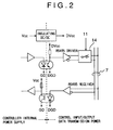
- the control input/output line 7 is based on the International Standard EIARS485. As shown in Fig. 2, the control input/output line 7, which electrically separates a control input/output transmission power source from an internal power source within each computer controller, whereby the computer controllers are electrically isolated from each other.
- interruption control line 6 and the controller control line 8 are based on a current drive system, and isolation between the lines 6 and 8 and the computer controllers are achieved by means of photocoupler.
- Reference numerals 10, 20 and 30 denote control units which control mainly the calculating operation of the controllers; 11, 21 and 31 denote diagnosers for detecting the associated control states of the control units; 12, 22 and 32 output units of control output data; 13, 23 and 33 input units of control input data; 14, 24 and 34 control output switches; 15, 25 and 35 synchronous interruption control units for the computer controllers; 16, 26 and 36 communication units for control data exchange between the computer controllers, respectively. Further, input lines 17, 27 and 37 are used to set priority orders for the control units 10, 20 and 30 to determine the order in which the computer controllers issue control outputs to the control object 4.
- the three computer controllers 1, 2 and 3 will be sometimes called the A system, the B system and the C system.
- the priority is set on the aforementioned priority input lines 17, 27 and 37 in an order of the A system, the B system and the C system in such a manner that one of the systems having the highest priority based on the majority decision always cyclically controls the control object 4 through a series of processes of data input, control processing and data output.
- the start timing of control cycle of each computer controller is started by an inter-system synchronous interrupt.
- Control clocks for the computer controllers are independent of each other.
- the inter-system synchronous interrupt is carried out under control of the synchronous interrupt control units 15, 25 and 35.
- Fig. 3 shows an internal structure of one of the synchronous interrupt control units
- Fig. 4 shows its synchronous interrupt generation timing.
- the illustrated synchronous interrupt control unit comprises a counter 151, a majority decision circuit 152 and an inter-system interface circuit 153 having photocouplers.
- the counter 151 receives a count start command from the control unit 10 and starts its counting operation.
- the counter 151 when completing its counting operation, sends a signal of logical level "1" to the majority decision circuit 152 and also externally outputs an its own system synchronizing signal 154.
- the other synchronous interrupt control units 25 and 35 are operated independently of each other, that is, when finishing the counting operation of the associated internal counter, externally outputs an its own system synchronizing signal as a signal of logical level "1".
- a synchronous interrupt to the associated controller is generated at such timing as shown by 1 in Fig. 4.
- the generation of the synchronization interrupt causes the respective counters to be updated at the same time, after which the counting operation of the counters of the three synchronous interrupt control units is completed at the same time, during which the generation of the synchronous interrupt is continued.
- the computer controller handles the inter-system synchronous interrupt as a trigger signal and starts its control cycle with one cycle of from 1 "synchronous interrupt” to 3 "synchronous interrupt".
- the respective computer controllers perform control data exchange therebetween by means of the communication units 16, 26 and 36.
- the respective computer control units 10, 20 and 30 independently parallelly execute such processing as shown in Fig. 5.
- control phase for data input and control of each control unit
- diagnosis phase for majority decision diagnosis between the control units and for output of control output data from any one of the control units.
- control phase refers to a phase in which the respective control units 10, 20 and 30 perform their calculating operation for control of the control object 4, whereas, the word “diagnosis phase” refers to a phase in which the control states of the three computer controllers are diagnosed.
- the diagnosis phase the self/mutual diagnosis of the computer controllers and the diagnosis of the inter-system data majority deciding processing on software basis are carried out.
- control units 10, 20 and 30 are connected to the control object 4 as follows.
- control units 10, 20 and 30 are always connected to the control input/output line 7 through the control data input units 13, 24 and 33 disposed therebetween. Accordingly, each control unit can always input the data state on the control input/output line 7. Meanwhile, the control data output units 12, 22 and 32 are connected to the control input/output line 7 through the control output switches 14, 24 and 34.
- the diagnosers 11, 21 and 31 of the control units 10, 20 and 30 decide, by majority decision, one of the control units 10, 20 and 30 to perform its control output and to controllably close associated one of the control output switches 14, 24 and 34 on the basis of the control states of the control units, whereby any one of the output units 12, 22 and 32 is connected to the control input/output line 7. How the diagnosers 11, 21 and 31 select one of the control units to perform its control output will be detailed below. single one of the output units to be determined by majority decision to perform its control output over the control object 4 will be called the main system and the other control units will be called the sub system, hereinafter.
- the inter-system synchronous interrupt processing is carried out (step 501 in Fig.
- control unit 10, 20 and 30 receive the same control status data from the control object 4 at the same time (step 502 in Fig. 5).
- the reception of the control status data in the control units is carried out in such a manner that the control unit as the then main system (which has the highest priority in the first control cycle or which was selected in the previous control cycle to issue the control output data) outputs an output request of the control status data to the control object and the respective control units receive the control status data from the control object.
- control over the control object is carried out on the basis of the identity input data (step 505), the control output data is exchanged among the control units (step 506) and ascertained through majority decision processing as the control output data (step 507).
- control input/output data of the control units 10, 20 and 30 are exchanged through their communication units 16, 26 and 36 and subjected to a majority decision operation in accordance with the software built in the control units 10, 20 and 20. Accordingly, if the majority decision operation based on the software is not normally carried out, then the triple multiplexing operation becomes meaningless.
- the respective control units 10, 20 and 30 are synchronized to generate and mutually exchange majority decision diagnosis data which are positively not satisfied in the triple system majority decision in accordance with the previously stored program (steps 509 and 510) and to confirm the detection ability of an abnormal data (step 511).
- control units 10, 20 and 30 When the control statuses of the control units 10, 20 and 30 are normal, the control units outputs 10, 20 and 30 output a signal indicative of satisfied majority decision as a control unit diagnosis signal to the diagnoser 11 in the control phase and output a signal indicative of not satisfied majority decision in the diagnosis phase, alternately.
- the control unit diagnosis signal which contains not only the diagnosis result of the majority decision operation but also a data indicative of one of the control units (including its own control unit) selected as the main system, is to the diagnoser of the control unit.
- Shown in Fig. 6 is how the control unit diagnosis signal varies in the control cycle.
- a frequency signal is employed for the purpose of reducing the number of interconnection signal lines between the control units 10, 20 and 30 and the diagnosers 11, 21 and 31 and also setting the internal circuit configurations of the diagnosers 11, 21 and 31 to be of a fail-safe logic.
- the control unit diagnosis signal is subjected to a frequency modulation when the majority decision operation is carried out and when one of the control units is selected as the main system in the control and diagnosis phases.
- Fig. 7 is a table showing an example of frequency allocation in the control unit diagnosis signal.
- reference symbol A denotes a state in which the A system is in the diagnosis phase and its own system is selected as the main system, in which case the diagnosis signal has a frequency of 515 ⁇ 135Hz.
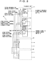
- Fig. 8 shows a schematic internal structure of the diagnoser 11 connected to the control unit 10 as well as interconnections between the diagnoser 11 and the other diagnosers 21 and 22.
- interconnections between the diagnosers 11, 21 and 31 of the respective system are effected by means of the system control line 8.
- the diagnoser 11 comprises a frequency discrimination circuit 111 for receiving the diagnosis frequency signal from the control unit 10, a diagnosis circuit 112 for making a decision of a majority decision operation result, and an output system selection circuit 113 for controllably selecting the main system for control output.
- a frequency separation circuit 1111 which is a frequency logic circuit (refer to JP-A-59-28725) based on a ring operation circuit, separates the diagnosis frequency signal received from the control unit 10 for fail-safe and outputs only one of seven signals ((Ai/Bi/Ci to (Acn/Bcn/Ccn)) associated with the diagnosis frequency signal allocations of Fig. 7.
- the output of the frequency separation circuit 1111 is subjected to a frequency operation to generate triple system control signals.
- the system control signals ((Ai/Bi/Ci) to (Ac/Bc/Cc) shown at the right side of Fig. 9) as outputs of the frequency discriminator 111 has the following functions.
- An initialization signal (Ai, Bi, Ci) is a start control signal for initializing the triple system configuration control.
- a control signal (An, Bn, Cn) is a signal indicative of the control unit being in the control phase.
- a diagnosis signal (At, Bt, Ct) is a signal indicative of the control unit being in the diagnosis phase.
- a self system selection signal (Aa, Ba, Ca) is a signal indicative of the each control unit 10, 20 or 30 judging its own system (as viewed from the A system) as the main system.
- An other-system 1 selection signal (Ab, Bb, Cb) is a signal indicative of the control unit 10, 20 or 30 deciding one (B system in this case) of the other systems as the main system.
- An other-system 2 selection signal (Ac, Bc, Cc) is a signal indicative of the control unit 10, 20 or 30 deciding the remainder (C system in this case) of the other systems as the main system.
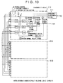
- Fig. 10 a schematic internal structure of the diagnosis circuit 112 in the diagnoser 11 as well as interconnections between the diagnosis circuit 112 and the other diagnosis circuits 212 and 312 of the other systems.
- the diagnosis circuit is used to confirm that the control units 10, 20 and 30 of the three systems normally perform their majority decision operation synchronously on the basis of the majority decision of the control and diagnosis signals of the systems and the continuity of its resultant frequency OR signal.
- the diagnosis circuit as a fault holding circuit is provided so that, when an abnormality is detected in the diagnosis of the majority decision operation, the abnormality detected control unit cannot be operated as one of the triple systems so long as the faulty control unit is not repaired and restarted.
- the fail-safe diagnosis of the triple system (A, B and C systems) and the start of the output system selection circuit are carried out by sending initialization frequency signals synchronously to the control units 10, 20 and 30 of the triple system.
- the control units of the triple system send the frequency signals indicative of the diagnosis and control as control unit diagnosis signals in synchronism with the control cycle, it is judged as normal.
- control units 10, 20 and 30 sends the initialization frequency signals to the diagnosers as the control unit diagnosis signals until synchronism is established, thereby setting the system configuration in the tentative normal condition.
- the reception of the initialization frequency signals of the other systems to the diagnosers 11, 21 and 31 as the fail-safe circuits are designed to be effected by the frequency OR signals of the other 2 systems and so that when its own system and at least one of the other systems send the initialization frequency signals, the initialization control is started.
- the initialization control when inter-system synchronism is established under the dummy normal condition of the output of the initialization frequency signals, switching is carried out to the computer diagnosis signals corresponding to the control phases of the diagnosis and gang or interlocking process of the control cycle to enter the control condition of the interlocked system.
- a switching time from the initialization frequency signal to the computer diagnosis signal for diagnosis and control corresponds to a delay in the operational time of the frequency logic.
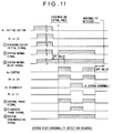
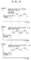
- Fig. 12 shows transitions in the control unit diagnosis signals in the initialization control of the triple system.
- a 3-system normal delay signal has a function of holding the fault condition of the diagnosis circuit.
- the 3-system normal delay signal changes to its frequency logic level of "0"
- a 1-system synchronous initial signal is changed to its frequency logical level of "1" by the frequency logic majority decision of the initialization signal (Ai, Bi, Ci). This causes a 2-system normal signal and a 3-system normal delay signal to be changed to their frequency logical level of "1".
- the 2-system normal signal is temporarily turned OFF.
- the off delay using frequency domain in that the frequency logic majority decision of the control signal (An, Bn, Cn) is satisfied during the presence of the remaining 3-system normal delay signal
- the 2-system normal signal is restored and the 3-system normal delay signal is continuously output.
- the respective control units are shifted to the diagnosis phases synchronously, the 2 -system normal signal is continuously output.
- the 3-system normal delay signal is changed to its frequency logic level of "0" so that the control unit 10 having the diagnosis circuit 112 cannot be returned to the triple system until it is restarted.
- each of the computers when self diagnosis in its own computer is normal, alternately executes the majority decision for the diagnosis of majority decision control necessary for system control processing and the majority decision for the real control of interlocked logic control. On the basis of these majority decision results, each computer outputs a computer diagnosis signal having a frequency of computer diagnosis status and a frequency of interlocking process status based on time division.
- the system diagnosis control is used to decide whether or not the frequency signal indicative of the state of the computer varies synchronously with the other systems.
- the system which decides the majority decision to be satisfied in the majority decision for the diagnosis of the majority decision control though the all-systems majority decision should be not satisfied, or the system, which decides the majority decision to be not satisfied in the majority decision for the real control of the interlocked logic control though the majority decision should be satisfied, outputs the diagnosis signal with its frequency signal not varied.
- an out-of-synchronism condition takes place and thus the associated system is separated from the triple system. That is, the system is not selected as an output system and thereafter will not be a control output system.
- the system which detects an abnormality through its self diagnosis, stops the output of the diagnosis signal to thereby separate itself from the triple system.
- the system in which an abnormality is detected through the mutual diagnosis, is specified as abnormal at the same time by the other two systems based on the majority decision for the real control of the interlocked logic control, whereby the system generates a majority decision non-coincidence to be separated from the triple system.
- the frequency logic causes the system to maintain its state as an abnormal system. Once the system is decided to be an abnormal system, it cannot be restored to the triple system so long as it does not perform its restarting operation in cooperation with the other systems.
- the output system selection circuit 113 comprises a majority decision circuit which preferentially selects an own-system selection signal over other system selection signals. This circuit selects the self system as the main system, that is, does not select any one or more of the other systems as the main system.
- the diagnosers 11, 21 and 31 are independently provided in the respective control units 10, 20 and 30 for diagnosis and output system selection.
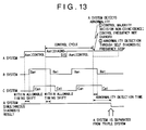
- the diagnoser and the output system selection circuit comprise each a fail-safe circuit based on the frequency logic, double selection in the output system selection will be positively avoided as shown in Figs. 10 to 13.
- Fig. 15 shows a structure of, in particular, one 14 of the control output switches 14, 24 and 34.
- the control output is carried out through a serial transmission line based on the Standard RS 485.
- the control output switch functions to connect and disconnect the control output to and from the transmission line by means of a relay. More in detail, the control output switches 14, 24 and 34 receives the frequency signals from the diagnosers 11, 21 and 31 and when the frequency logic level is "1", i.e., when one of the systems is selected as the output system, an AC amplifier in the associated control output switch drives the associated relay for fail-safe.
- Each of the computers of the triple system providing the fail-safe configuration control and the interlocked system contains a serial data transmission circuit for control output, but the serial data transmission circuit based on the Standard Specifications is not a fail-safe circuit.
- the interlocked system since one system selected as the control output system performs the control output, the multiplexing of the serial data transmission circuits for the control output becomes meaningless. A failure rate in the output processing is equivalent to that when the single serial data transmission circuit becomes faulty.
- fail-safe as the output processing device is realized by monitoring the control outputs of the systems other than the control output system of the multiplexed computers, by controllably separating the erroneous control output system from the signal system connection line at the time of detecting an erroneous control output in the control output systems, and by employing such a transmission control protocol that an interruption in the course of output of the control output signal results in stoppage of an erroneous control output.
- the computer of the control output system can monitor its control output condition and the other computers can monitor their control output conditions.
- the two systems When the two systems detects an abnormality in the control output, i.e., that a data other than the data decided on the majority decision of the interlocked logic control is output through the monitoring operation, the two systems, which detected the abnormality, can cooperate to disconnect the control output system from the signal system through the connection line.
- the monitoring of the control input and output and the disconnection of the connection line at the occurrence of an abnormality are illustrated in Fig. 16.
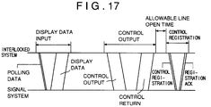
- Fig.17 Shown in Fig.17 is a protocol for data transmission control between the interlocked and signal systems. According to this protocol, one control output is completed by:
- the computers of the systems other than the control output system can detect the erroneous control output.
- the computers of the systems other than the control output system can set the abnormality-detected computer to be an abnormal system and prior to the output of a control registration, can cut off the connection line between the interlocked and signal systems, whereby any erroneous control output can be avoided.
Landscapes
- Engineering & Computer Science (AREA)
- Theoretical Computer Science (AREA)
- Physics & Mathematics (AREA)
- General Engineering & Computer Science (AREA)
- General Physics & Mathematics (AREA)
- Quality & Reliability (AREA)
- Computer Hardware Design (AREA)
- Software Systems (AREA)
- Safety Devices In Control Systems (AREA)
- Hardware Redundancy (AREA)
- Multi Processors (AREA)
Applications Claiming Priority (2)
| Application Number | Priority Date | Filing Date | Title |
|---|---|---|---|
| JP3072774A JP2682251B2 (ja) | 1991-04-05 | 1991-04-05 | 多重化制御装置 |
| JP72774/91 | 1991-04-05 |
Publications (3)
| Publication Number | Publication Date |
|---|---|
| EP0507299A2 true EP0507299A2 (de) | 1992-10-07 |
| EP0507299A3 EP0507299A3 (en) | 1994-08-17 |
| EP0507299B1 EP0507299B1 (de) | 1998-07-15 |
Family
ID=13499060
Family Applications (1)
| Application Number | Title | Priority Date | Filing Date |
|---|---|---|---|
| EP19920105695 Expired - Lifetime EP0507299B1 (de) | 1991-04-05 | 1992-04-02 | Lose gekoppelte Multiplex-Steuervorrichtung |
Country Status (3)
| Country | Link |
|---|---|
| EP (1) | EP0507299B1 (de) |
| JP (1) | JP2682251B2 (de) |
| DE (1) | DE69226214T2 (de) |
Cited By (1)
| Publication number | Priority date | Publication date | Assignee | Title |
|---|---|---|---|---|
| EP3273352A1 (de) * | 2016-07-21 | 2018-01-24 | Supercomputing Systems AG | Computerisiertes system |
Families Citing this family (8)
| Publication number | Priority date | Publication date | Assignee | Title |
|---|---|---|---|---|
| JP3348146B2 (ja) | 1997-12-05 | 2002-11-20 | 株式会社日立製作所 | 通信制御装置 |
| US6654648B2 (en) | 2000-04-03 | 2003-11-25 | Toyota Jidosha Kabushiki Kaisha | Technique of monitoring abnormality in plurality of CPUs or controllers |
| JP4491479B2 (ja) * | 2007-09-27 | 2010-06-30 | 株式会社日立製作所 | 分散制御システム |
| JP4818349B2 (ja) * | 2008-12-24 | 2011-11-16 | 株式会社東芝 | 分散システムおよび同システムの多重化制御方法 |
| JP4818379B2 (ja) * | 2009-02-26 | 2011-11-16 | 株式会社東芝 | フェイルオーバ機能を持つ分散システムおよび同システムにおけるフェイルオーバ方法 |
| JP4806044B2 (ja) * | 2009-03-06 | 2011-11-02 | 株式会社東芝 | フェイルオーバ機能を持つ分散システムおよび同システムにおけるフェイルオーバ方法 |
| JP5140121B2 (ja) * | 2010-08-26 | 2013-02-06 | 三菱電機株式会社 | 制御システム |
| JP6748460B2 (ja) * | 2016-03-22 | 2020-09-02 | Kyb株式会社 | 制御装置 |
Family Cites Families (5)
| Publication number | Priority date | Publication date | Assignee | Title |
|---|---|---|---|---|
| DE2647367C3 (de) * | 1976-10-20 | 1982-12-09 | Siemens AG, 1000 Berlin und 8000 München | Redundante Prozeßsteueranordnung |
| JPS5588429A (en) * | 1978-12-26 | 1980-07-04 | Nec Corp | Tripled circuit |
| JPS59212902A (ja) * | 1983-05-18 | 1984-12-01 | Hitachi Ltd | 多重化制御装置 |
| JPH0619641B2 (ja) * | 1983-07-15 | 1994-03-16 | 株式会社日立製作所 | 多重系制御システムのデータ管理方式 |
| WO1987007793A1 (en) * | 1986-06-13 | 1987-12-17 | Valtion Teknillinen Tutkimuskeskus | Method for realizing a fault-tolerant electronic system and a corresponding system |
-
1991
- 1991-04-05 JP JP3072774A patent/JP2682251B2/ja not_active Expired - Lifetime
-
1992
- 1992-04-02 DE DE1992626214 patent/DE69226214T2/de not_active Expired - Lifetime
- 1992-04-02 EP EP19920105695 patent/EP0507299B1/de not_active Expired - Lifetime
Cited By (3)
| Publication number | Priority date | Publication date | Assignee | Title |
|---|---|---|---|---|
| EP3273352A1 (de) * | 2016-07-21 | 2018-01-24 | Supercomputing Systems AG | Computerisiertes system |
| CH712732A1 (de) * | 2016-07-21 | 2018-01-31 | Supercomputing Systems Ag | Computerisiertes System. |
| US10691080B2 (en) | 2016-07-21 | 2020-06-23 | Supercomputing Systems Ag | Computerised system |
Also Published As
| Publication number | Publication date |
|---|---|
| JPH04307633A (ja) | 1992-10-29 |
| DE69226214T2 (de) | 1999-04-08 |
| EP0507299A3 (en) | 1994-08-17 |
| EP0507299B1 (de) | 1998-07-15 |
| DE69226214D1 (de) | 1998-08-20 |
| JP2682251B2 (ja) | 1997-11-26 |
Similar Documents
| Publication | Publication Date | Title |
|---|---|---|
| EP0507299B1 (de) | Lose gekoppelte Multiplex-Steuervorrichtung | |
| EP0494695B1 (de) | Ringübertragungssystem mit einem Bussicherungssystem und Verfahren | |
| CN113682348A (zh) | 一种基于通信的联锁新型双机切换方法 | |
| US7492706B1 (en) | Frame synchronization and fault protection for a telecommunications device | |
| HK1006053B (en) | Loop mode transmission system with bus mode backup and a method of maintaining continuity thereof | |
| CN113835337B (zh) | 一种列车网络冗余控制的方法与系统 | |
| JPH11112389A (ja) | 無瞬断回線切替システム及び伝送装置 | |
| WO2006080433A1 (ja) | 情報処理装置および情報処理方法 | |
| CN109306875A (zh) | 一种汽轮机deh双控制器同步热备冗余切换装置及方法 | |
| CN118337559B (zh) | 高可靠拓扑结构的列车组网系统及方法 | |
| CN115664174B (zh) | 一种结合同步与通信状态筛选共享同步信号的方法 | |
| JPH06348524A (ja) | 多重化制御装置 | |
| JPH1132449A (ja) | 分散形監視制御システム | |
| JP3302499B2 (ja) | 2重系装置 | |
| CN117950300A (zh) | 一种基于控制器的冗余控制方法、系统及存储介质 | |
| JPH11168502A (ja) | 通信障害処理装置及び方法 | |
| JP3261014B2 (ja) | データ処理システムにおけるモジュール交換方法および自己診断方法 | |
| US6763021B1 (en) | Monitoring switching method and apparatus for redundant part of transmission apparatus | |
| JP2776417B2 (ja) | 多重化クロック分配方式 | |
| CN120068052A (zh) | 一种基于多核的2×2002安全计算机平台无缝切系的系统及方法 | |
| CN115037674B (zh) | 一种中央控制系统单机及多设备冗余备份方法 | |
| JPH085380B2 (ja) | 並列多重電子連動装置 | |
| CN116799756A (zh) | 一种多端输电线路差动保护系统及方法 | |
| JPH0454747A (ja) | データ転送システム | |
| JPH011350A (ja) | ゲ−トウェイのバックアップ方式 |
Legal Events
| Date | Code | Title | Description |
|---|---|---|---|
| PUAI | Public reference made under article 153(3) epc to a published international application that has entered the european phase |
Free format text: ORIGINAL CODE: 0009012 |
|
| AK | Designated contracting states |
Kind code of ref document: A2 Designated state(s): DE GB SE |
|
| PUAL | Search report despatched |
Free format text: ORIGINAL CODE: 0009013 |
|
| AK | Designated contracting states |
Kind code of ref document: A3 Designated state(s): DE GB SE |
|
| 17P | Request for examination filed |
Effective date: 19940923 |
|
| 17Q | First examination report despatched |
Effective date: 19941117 |
|
| GRAG | Despatch of communication of intention to grant |
Free format text: ORIGINAL CODE: EPIDOS AGRA |
|
| GRAG | Despatch of communication of intention to grant |
Free format text: ORIGINAL CODE: EPIDOS AGRA |
|
| GRAH | Despatch of communication of intention to grant a patent |
Free format text: ORIGINAL CODE: EPIDOS IGRA |
|
| GRAH | Despatch of communication of intention to grant a patent |
Free format text: ORIGINAL CODE: EPIDOS IGRA |
|
| GRAA | (expected) grant |
Free format text: ORIGINAL CODE: 0009210 |
|
| AK | Designated contracting states |
Kind code of ref document: B1 Designated state(s): DE GB SE |
|
| REF | Corresponds to: |
Ref document number: 69226214 Country of ref document: DE Date of ref document: 19980820 |
|
| PLBE | No opposition filed within time limit |
Free format text: ORIGINAL CODE: 0009261 |
|
| STAA | Information on the status of an ep patent application or granted ep patent |
Free format text: STATUS: NO OPPOSITION FILED WITHIN TIME LIMIT |
|
| 26N | No opposition filed | ||
| REG | Reference to a national code |
Ref country code: GB Ref legal event code: IF02 |
|
| PGFP | Annual fee paid to national office [announced via postgrant information from national office to epo] |
Ref country code: DE Payment date: 20110330 Year of fee payment: 20 Ref country code: SE Payment date: 20110412 Year of fee payment: 20 Ref country code: GB Payment date: 20110330 Year of fee payment: 20 |
|
| REG | Reference to a national code |
Ref country code: DE Ref legal event code: R071 Ref document number: 69226214 Country of ref document: DE |
|
| REG | Reference to a national code |
Ref country code: DE Ref legal event code: R071 Ref document number: 69226214 Country of ref document: DE |
|
| REG | Reference to a national code |
Ref country code: GB Ref legal event code: PE20 Expiry date: 20120401 |
|
| PG25 | Lapsed in a contracting state [announced via postgrant information from national office to epo] |
Ref country code: GB Free format text: LAPSE BECAUSE OF EXPIRATION OF PROTECTION Effective date: 20120401 |
|
| REG | Reference to a national code |
Ref country code: SE Ref legal event code: EUG |
|
| PG25 | Lapsed in a contracting state [announced via postgrant information from national office to epo] |
Ref country code: DE Free format text: LAPSE BECAUSE OF EXPIRATION OF PROTECTION Effective date: 20120403 |