EP0504484A1 - Elément pour revêtement de murs - Google Patents
Elément pour revêtement de murs Download PDFInfo
- Publication number
- EP0504484A1 EP0504484A1 EP91121002A EP91121002A EP0504484A1 EP 0504484 A1 EP0504484 A1 EP 0504484A1 EP 91121002 A EP91121002 A EP 91121002A EP 91121002 A EP91121002 A EP 91121002A EP 0504484 A1 EP0504484 A1 EP 0504484A1
- Authority
- EP
- European Patent Office
- Prior art keywords
- wall
- plates
- covering element
- element according
- sound
- Prior art date
- Legal status (The legal status is an assumption and is not a legal conclusion. Google has not performed a legal analysis and makes no representation as to the accuracy of the status listed.)
- Withdrawn
Links
- 239000011358 absorbing material Substances 0.000 claims abstract description 10
- 238000005253 cladding Methods 0.000 claims description 11
- 239000000463 material Substances 0.000 claims description 8
- 239000002023 wood Substances 0.000 claims description 6
- 230000001154 acute effect Effects 0.000 claims description 5
- 230000000694 effects Effects 0.000 abstract description 9
- 238000004026 adhesive bonding Methods 0.000 description 3
- 239000011888 foil Substances 0.000 description 1
Images
Classifications
-
- E—FIXED CONSTRUCTIONS
- E04—BUILDING
- E04B—GENERAL BUILDING CONSTRUCTIONS; WALLS, e.g. PARTITIONS; ROOFS; FLOORS; CEILINGS; INSULATION OR OTHER PROTECTION OF BUILDINGS
- E04B1/00—Constructions in general; Structures which are not restricted either to walls, e.g. partitions, or floors or ceilings or roofs
- E04B1/62—Insulation or other protection; Elements or use of specified material therefor
- E04B1/74—Heat, sound or noise insulation, absorption, or reflection; Other building methods affording favourable thermal or acoustical conditions, e.g. accumulating of heat within walls
- E04B1/82—Heat, sound or noise insulation, absorption, or reflection; Other building methods affording favourable thermal or acoustical conditions, e.g. accumulating of heat within walls specifically with respect to sound only
-
- E—FIXED CONSTRUCTIONS
- E04—BUILDING
- E04F—FINISHING WORK ON BUILDINGS, e.g. STAIRS, FLOORS
- E04F13/00—Coverings or linings, e.g. for walls or ceilings
- E04F13/07—Coverings or linings, e.g. for walls or ceilings composed of covering or lining elements; Sub-structures therefor; Fastening means therefor
- E04F13/08—Coverings or linings, e.g. for walls or ceilings composed of covering or lining elements; Sub-structures therefor; Fastening means therefor composed of a plurality of similar covering or lining elements
- E04F13/0864—Coverings or linings, e.g. for walls or ceilings composed of covering or lining elements; Sub-structures therefor; Fastening means therefor composed of a plurality of similar covering or lining elements composed of superposed elements which overlap each other and of which the flat outer surface includes an acute angle with the surface to cover
Definitions
- the invention relates to a wall cladding element, in particular for interior walls, consisting of at least two overlapping panels which are attached to a wall e.g. can be attached by means of a slatted frame.
- the object of the invention is to achieve a sound-absorbing effect in such wall cladding elements.
- the plates are arranged at a distance from one another in the overlap region, so that a sound-absorbing pocket-shaped space is formed between them.
- the lower surface of the overlapping upper plate facing the wall is preferably covered with a sound-absorbing material in the overlap region.
- the panels can be kept at a predetermined distance from one another, for example by means of strips, the bottom side surfaces of the strips expediently also being coated with a sound-absorbing material.
- the plates are preferably arranged parallel to one another and at an acute angle to the wall, which can be approximately 2-20 °.
- the distance between the plates in the overlap area is approximately 5-40 mm and the length of the overlap of two plates is approximately in the range of 5% to 50% of the length of a plate.
- the plates preferably consist of wood, a wood-based material or a plastic material.
- An advantage of the wall covering elements according to the invention is that they have a sound-absorbing effect without the absorbing means being visible from the outside, that is to say from the room.
- the upper surface of the panels facing the room can therefore be kept in any desired decor without impairing the sound-absorbing effect.
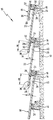
- the wall covering element 10 shown consists of at least two plates, which are generally designated 18. A large number of such wall cladding elements 10 together form a complete cladding of a wall 12 of any room, the wall cladding according to the invention preferably being intended for lecture halls, congress halls, exhibition halls etc.
- Slats 14 or a complete slatted frame are fastened to the wall 12 at horizontal intervals, and the wall cladding elements 10 or the plates 18 are attached to this slatted frame 14.
- any other suitable substructure can also be used to hold the plates 18.
- the slats 14 have on their side facing the room side a bevelled extending end surface 16 of the wall 12 with an acute angle of for example 2 - 20 o forms.
- the plates 18 are fastened on these end faces 16.
- the plates can be connected to the slats 14 by means of any suitable fastening elements, for example Screws, nails, staples or even by gluing. Since the panels overlap, the fasteners are never visible.
- the overlapping of two panels and their sound-absorbing effect will now be described with reference to the two panels 20, 22, which together form a cladding element.
- the upper region 40 of each plate, for example plate 22 is overlapped by the lower region 36 of the next higher plate, for example plate 20.
- the lower region 36 of plate 20 overlaps the upper region 40 of the plate 22, the length of the overlap being designated B.
- a bar 24 is arranged between the upper area 40 of the plate 22 and the lower area 36 of the plate 20, which advantageously runs parallel to the slats 14 and practically horizontally.
- the thickness of the strip 24 determines the clear distance A between the two plates 20, 22, that is to say in particular between the lower region 36 of the upper plate 20 and the upper region 40 of the lower plate 22.
- a pocket-shaped space 26 is formed in the overlap region between the two plates 20 and 22, which is defined by the lower region 36 of the upper plate 20, the upper region 40 of the lower plate 22 and Bar 24 is limited.
- a good sound-absorbing effect of the wall cladding elements 10 is already achieved through this pocket-shaped space 26 between two panels.
- the strip 24 (instead of which individual blocks can also be used) is suitably connected to the underlying plate, for example the plate 22, for example by means of screws, pins, clips or by gluing. Since the strip 24 is covered by the overlying plate 20, the fastening means are not visible from the room.
- the upper plate 20 can be placed loosely on the strip 24, but fasteners can also be used here, but are expediently not visible from the outside, that is to say from the room.
- the lower surface 30 of the upper plate 20 is now covered over the entire overlap region B with a suitable sound-absorbing material 28, which can be attached to the respective plate in any suitable manner, for example by nails, pens , Brackets or by gluing.
- a suitable sound-absorbing material 28 can be attached to the respective plate in any suitable manner, for example by nails, pens , Brackets or by gluing.
- a large selection of soundproofing materials suitable for this purpose in the form of foils or mats are commercially available.
- the lower longitudinal side surface 32 of the strips 24 is expediently also coated with such a sound-absorbing material 28, as a result of which the sound-absorbing effect is increased.
- each plate 18, 20, 22 can be designed in any way, for example obliquely cut off, rounded or corrugated or the like.
- the upper surfaces of the panels facing the room can be given any desired decor, since the sound-absorbing materials 28 are only arranged inside the pockets 26 and therefore from the room are not visible here.
- the plates are parallel among themselves and constitute, as already explained above, with the wall 12 forms an acute angle of eg 2-20 o.
- the clear distance A between two plates in the overlap region, that is to say the height of the pockets 26 is approximately 5-40 mm and the length of the overlap B is preferably approximately 5% to approximately 50% of the total length of a plate, measured practically in the vertical direction .
- Wood, a wood-based material or any suitable plastic can preferably be used as the material for the panels. Furthermore, lighting devices can advantageously be accommodated within the pockets 26, as a result of which pleasant indirect lighting of the wall cladding is achieved.
- the plates 18, 20, 22 can optionally also be arranged parallel to the wall 12. If desired, the overlap area B of the plates 18, 20, 22 can only be partially coated with the sound-absorbing material 28, but if necessary the entire rear side 30 of the plates can also be covered with this material 28.
Landscapes
- Engineering & Computer Science (AREA)
- Architecture (AREA)
- Physics & Mathematics (AREA)
- Civil Engineering (AREA)
- Structural Engineering (AREA)
- Acoustics & Sound (AREA)
- Electromagnetism (AREA)
- Building Environments (AREA)
- Finishing Walls (AREA)
Applications Claiming Priority (2)
| Application Number | Priority Date | Filing Date | Title |
|---|---|---|---|
| DE9103370U | 1991-03-19 | ||
| DE9103370U DE9103370U1 (de) | 1991-03-19 | 1991-03-19 | Wandverkleidungselement |
Publications (1)
| Publication Number | Publication Date |
|---|---|
| EP0504484A1 true EP0504484A1 (fr) | 1992-09-23 |
Family
ID=6865457
Family Applications (1)
| Application Number | Title | Priority Date | Filing Date |
|---|---|---|---|
| EP91121002A Withdrawn EP0504484A1 (fr) | 1991-03-19 | 1991-12-06 | Elément pour revêtement de murs |
Country Status (2)
| Country | Link |
|---|---|
| EP (1) | EP0504484A1 (fr) |
| DE (1) | DE9103370U1 (fr) |
Families Citing this family (1)
| Publication number | Priority date | Publication date | Assignee | Title |
|---|---|---|---|---|
| DE102020112974A1 (de) * | 2020-05-13 | 2020-07-23 | Dachkeramik Meyer-Holsen GmbH | Verkleidungselement für eine Fassaden- oder Dachverkleidung sowie Fassaden- oder Dachverkleidung mit mehreren Verkleidungselementen |
Citations (4)
| Publication number | Priority date | Publication date | Assignee | Title |
|---|---|---|---|---|
| GB1142698A (en) * | 1966-12-01 | 1969-02-12 | Kins Developments Ltd | Sound absorbent walls |
| DE2936776A1 (de) * | 1979-09-12 | 1981-03-19 | G.A. Pfleiderer GmbH & Co KG, 8430 Neumarkt | Laermschutzwand |
| DE3032947A1 (de) * | 1980-09-02 | 1982-04-15 | Siebel, Lothar, 5100 Aachen | Schallabsorbierend angebrachte fassadenplatten |
| FR2630762A1 (fr) * | 1988-04-28 | 1989-11-03 | Tuyaux Bonna | Structure d'ecran absorbant pour mur et revetement de paroi anti-bruit |
-
1991
- 1991-03-19 DE DE9103370U patent/DE9103370U1/de not_active Expired - Lifetime
- 1991-12-06 EP EP91121002A patent/EP0504484A1/fr not_active Withdrawn
Patent Citations (4)
| Publication number | Priority date | Publication date | Assignee | Title |
|---|---|---|---|---|
| GB1142698A (en) * | 1966-12-01 | 1969-02-12 | Kins Developments Ltd | Sound absorbent walls |
| DE2936776A1 (de) * | 1979-09-12 | 1981-03-19 | G.A. Pfleiderer GmbH & Co KG, 8430 Neumarkt | Laermschutzwand |
| DE3032947A1 (de) * | 1980-09-02 | 1982-04-15 | Siebel, Lothar, 5100 Aachen | Schallabsorbierend angebrachte fassadenplatten |
| FR2630762A1 (fr) * | 1988-04-28 | 1989-11-03 | Tuyaux Bonna | Structure d'ecran absorbant pour mur et revetement de paroi anti-bruit |
Also Published As
| Publication number | Publication date |
|---|---|
| DE9103370U1 (de) | 1991-06-20 |
Similar Documents
| Publication | Publication Date | Title |
|---|---|---|
| EP0504629A2 (fr) | Elément absorbant le son en forme de panneau, et dispositif absorbant le son | |
| DE1609784B2 (fr) | ||
| CH619283A5 (fr) | ||
| EP0551307A1 (fr) | Battant de porte et son procede de fabrication. | |
| DE2043784B2 (de) | Schalldämmende Schale für mehrschalige Raumwandungen | |
| AT402959B (de) | Türblatt | |
| EP0504484A1 (fr) | Elément pour revêtement de murs | |
| DE29722941U1 (de) | Holzwerkstoffplatte | |
| CH683855A5 (de) | Schallabsorptionsplatte. | |
| DE29812919U1 (de) | Leimbinderelement zur Herstellung von Möbeln, Türen, Fußboden-, Wandbelägen u.dgl. | |
| DE2623355A1 (de) | Fassadenplatte | |
| DE2112625A1 (de) | Fussbodenplatte | |
| DE2730087C2 (fr) | ||
| DE2911646C2 (de) | Eckverbindung von Wänden für Schallschluck-Kabinen | |
| DE3733778C2 (fr) | ||
| DE3909529A1 (de) | Keramisches trennwandelement fuer trennwaende und raumteiler | |
| DE2223217C3 (de) | Versetzbare Trennwand | |
| DE9102819U1 (de) | Türblatt | |
| DE2305642A1 (de) | Wandelement fuer selbst tragende trennwaende | |
| DE3520066C2 (fr) | ||
| DE1254327B (de) | Anordnung und Ausbildung von versetzbaren Trennwaenden in einem nach oben von einer Unterdecke begrenzten Raum | |
| AT395890B (de) | Bogenfoermig verschiebbares schiebetor | |
| DE10052070A1 (de) | Mobile Trennwand | |
| DE3345965A1 (de) | Trennwand in wohn- und wirtschaftsraeumen, insbesondere an bord von schiffen | |
| DE3811064C2 (fr) |
Legal Events
| Date | Code | Title | Description |
|---|---|---|---|
| PUAI | Public reference made under article 153(3) epc to a published international application that has entered the european phase |
Free format text: ORIGINAL CODE: 0009012 |
|
| AK | Designated contracting states |
Kind code of ref document: A1 Designated state(s): AT BE CH DE DK ES FR GB IT LI NL SE |
|
| STAA | Information on the status of an ep patent application or granted ep patent |
Free format text: STATUS: THE APPLICATION IS DEEMED TO BE WITHDRAWN |
|
| 18D | Application deemed to be withdrawn |
Effective date: 19930324 |