EP0503754A1 - Zwei-stufiger verjüngte Blattfeder-Aufbau - Google Patents
Zwei-stufiger verjüngte Blattfeder-Aufbau Download PDFInfo
- Publication number
- EP0503754A1 EP0503754A1 EP92300263A EP92300263A EP0503754A1 EP 0503754 A1 EP0503754 A1 EP 0503754A1 EP 92300263 A EP92300263 A EP 92300263A EP 92300263 A EP92300263 A EP 92300263A EP 0503754 A1 EP0503754 A1 EP 0503754A1
- Authority
- EP
- European Patent Office
- Prior art keywords
- leaf
- end surfaces
- trailer
- leaf spring
- tapered
- Prior art date
- Legal status (The legal status is an assumption and is not a legal conclusion. Google has not performed a legal analysis and makes no representation as to the accuracy of the status listed.)
- Granted
Links
Images


Classifications
-
- B—PERFORMING OPERATIONS; TRANSPORTING
- B60—VEHICLES IN GENERAL
- B60G—VEHICLE SUSPENSION ARRANGEMENTS
- B60G11/00—Resilient suspensions characterised by arrangement, location or kind of springs
- B60G11/02—Resilient suspensions characterised by arrangement, location or kind of springs having leaf springs only
-
- B—PERFORMING OPERATIONS; TRANSPORTING
- B60—VEHICLES IN GENERAL
- B60G—VEHICLE SUSPENSION ARRANGEMENTS
- B60G5/00—Resilient suspensions for a set of tandem wheels or axles having interrelated movements
- B60G5/04—Resilient suspensions for a set of tandem wheels or axles having interrelated movements with two or more pivoted arms, the movements of which are resiliently interrelated, e.g. the arms being rigid
- B60G5/047—Resilient suspensions for a set of tandem wheels or axles having interrelated movements with two or more pivoted arms, the movements of which are resiliently interrelated, e.g. the arms being rigid at least one arm being resilient, e.g. a leafspring
-
- B—PERFORMING OPERATIONS; TRANSPORTING
- B60—VEHICLES IN GENERAL
- B60G—VEHICLE SUSPENSION ARRANGEMENTS
- B60G11/00—Resilient suspensions characterised by arrangement, location or kind of springs
- B60G11/02—Resilient suspensions characterised by arrangement, location or kind of springs having leaf springs only
- B60G11/04—Resilient suspensions characterised by arrangement, location or kind of springs having leaf springs only arranged substantially parallel to the longitudinal axis of the vehicle
-
- B—PERFORMING OPERATIONS; TRANSPORTING
- B60—VEHICLES IN GENERAL
- B60G—VEHICLE SUSPENSION ARRANGEMENTS
- B60G11/00—Resilient suspensions characterised by arrangement, location or kind of springs
- B60G11/02—Resilient suspensions characterised by arrangement, location or kind of springs having leaf springs only
- B60G11/10—Resilient suspensions characterised by arrangement, location or kind of springs having leaf springs only characterised by means specially adapted for attaching the spring to axle or sprung part of the vehicle
- B60G11/107—Sliding or rolling mountings
-
- B—PERFORMING OPERATIONS; TRANSPORTING
- B60—VEHICLES IN GENERAL
- B60G—VEHICLE SUSPENSION ARRANGEMENTS
- B60G2206/00—Indexing codes related to the manufacturing of suspensions: constructional features, the materials used, procedures or tools
- B60G2206/01—Constructional features of suspension elements, e.g. arms, dampers, springs
- B60G2206/40—Constructional features of dampers and/or springs
- B60G2206/42—Springs
- B60G2206/428—Leaf springs
-
- B—PERFORMING OPERATIONS; TRANSPORTING
- B60—VEHICLES IN GENERAL
- B60G—VEHICLE SUSPENSION ARRANGEMENTS
- B60G2206/00—Indexing codes related to the manufacturing of suspensions: constructional features, the materials used, procedures or tools
- B60G2206/01—Constructional features of suspension elements, e.g. arms, dampers, springs
- B60G2206/80—Manufacturing procedures
- B60G2206/81—Shaping
- B60G2206/8109—Shaping by rolling
Definitions
- the present invention relates to commercial vehicle suspensions and, more particularly, to a dual-stage tapered leaf spring for use in a tractor-trailer suspension assembly.
- Multi-leaf springs are a class of leaf springs having a plurality of three or more constant thickness stepped-length leafs which are stacked to form a constant rate leaf spring assembly.
- single-stage multi-leaf springs are not designed to differentiate between "loaded” and “unloaded” trailer operation and thus normally provide a firm or “stiff' ride during loaded operation.
- this "stiff" ride causes excessive suspension vibration and reduced wheel control during "unloaded” trailer operation which detrimentally impacts the useful service life of the trailer while causing an undesirably harsh ride for the vehicle operator.
- trailer suspension applications equipped with dual-stage leaf springs for providing a variable or progressive rate have been extremely limited due to the availability of pneumatic systems.
- dual-stage leaf springs have been used it is common to employ a massive and in-efficient first stage multi-leaf spring having an additional second stage leaf mounted thereto.
- the first stage multi-leaf spring is sized to provide the low rate "soft" ride when the trailer is unloaded (i.e. curb load) with the second stage leaf being inactive.
- the second stage leaf becomes actively loaded for causing the overall rate to increase so as to produce a firmer ride.
- a "helper" spring is mounted above the main spring of the first-stage multi-leaf spring and does not support any load until it engages camming pads for resisting further deflection of the multi-leaf first stage.
- the change in rate and, in turn, the ride stiffness is necessarily abrupt and harsh.
- dual-stage leaf springs may have one or more relatively thick second stages leafs mounted below and adjacent to the shortest leaf of the "first stage" portion of the multi-leaf leaf spring. Upon deflection, rolling contact is made between the second stage leafs and the first stage for producing the increased rate. Again however, the rate transition is typically abrupt.
- dual-stage leaf springs have been used in various light-duty truck applications, such springs have not been used in the heavy-duty trailer industry. This is primarily due to the fact that heavy-duty trailer suspensions must be designed to function for a significantly larger load-carrying range than is required of modern light-duty vehicles. As such, dual-stage multi-leaf springs are heavy and require a significant range of deflection to provide the desired rate transition. These design constraints have made utilization of conventional multi-leaf dual-stage springs impractical for many trailer suspension applications.
- pneumatic suspension systems are being installed in trailers to provide means for variably adjusting the rate in response to changes in the load carried by the trailer.
- pneumatic suspension systems are typically quite expensive and require additional structural components for providing sufficient roll and wind-up stiffness in most commercial heavy-duty trailer applications.
- the present invention is directed to an improved dual-leaf tapered leaf spring assembly having a main or first tapered leaf defining a first stage rate and a second tapered leaf operable to define a second stage rate.
- the first and second leafs are formed to include a tapered thickness profile which closely approximates a true modified parabolic taper.
- the remote ends of the main leaf operably engage hanger cams suspended from the trailer frame.
- the second leaf is operably mounted below the main leaf and is adapted to move between positions of non-engagement and engagement with the main leaf in response to deflection of the leaf spring assembly.
- the "approximated" modified parabolic profiles for each of the main and second leafs are adapted to provide a smooth non-linear transition between the first and second stage rates (i.e. between "curb" and "design” loads) as compared to the excessively abrupt linear transition associated with conventional dual-stage multi-leaf springs. More specifically, the smooth non-linear rate transition is generally parabolic and includes first and second arcuate transition regions.
- the first arcuate transition region is relatively large and occurs upon the cranked ends of the second tapered leaf engaging and rolling in on the main leaf upon continued axle displacement for effectively shortening the second leaf moment arm.
- the second arcuate transition region occurs upon continued leaf spring deflection in response to the main leaf rolling in on the hanger cams for effectively shortening the main leaf moment arm.
- the first and second arcuate regions of the transition curve are interconnected by a fairly linear load deflection region which occurs following second leaf engagement and prior to the shortening of the main leaf.
- the main tapered leaf of the dual-stage dual-leaf spring of the present invention is designed to have a higher working (i.e. bending) stress level than the second tapered leaf.
- the working stresses for each of the tapered leafs are uniformly distributed over their entire length due to the "approximated" modified parabolic tapered thickness profile of each of the leafs.
- the service life and ride characteristics associated with the lightweight high-stress tapered leaf spring assembly of the present invention are superior to conventional non-tapered and linearly tapered multi-leaf springs while causing uniform stress distribution in a manner heretobefore only associated with true parabolical tapered profile.
- the present invention is material efficient and designed to maintain sufficient interleaf clearance for permitting smooth second leaf to main leaf engagement without causing excessive interleaf contact or friction upon the full range of axle deflection. Elimination of interleaf friction lends itself to substantially lower frictional losses whereby the available potential energy (i.e. damping) is substantially increased.
- the tapered thickness profile for each the first and second leafs incorporates a series of successive linearly tapered increments which approximate a true modified parabolic taper profile. More particularly, the successive linearly tapered increments define a plurality of sequential transition points which each define a different amount of thickness taper per unit of length measure for effectively minimizing the mass of material used while concurrently achieving uniform stress levels. As such, the "approximated" modified parabolic taper effectively replicates a true parabolic tapered spring in configuration and function so as to provide maximized spring efficiency at a realistic production cost.
- the present invention is directed to a variable or progressive rate leaf spring assembly for use in tractor-trailer vehicle suspension systems.
- the lightweight high-stress tapered leaf spring assembly of the present invention is readily adapted for installation in virtually all single, tandem and/or multi-axle trailer suspension systems for supporting and damping relative movement between the trailer frame and each of the axles.
- a dual-stage dual-leaf spring assembly which incorporates a tapered thickness profile adapted to approximate a "modified parabolic" taper.
- the rate is the leaf spring's change in load per unit of deflection (lbs/inch).
- Static deflection (inches) is derived by dividing the rate at a static load position by the static load for determining the "stiffness" of the suspension and the ride frequency of the vehicle.
- a “soft” ride requires a relatively large static deflection of the vehicle's suspension system while a “firm” ride generally requires a smaller amount of static deflection.
- the tapered dual-leaf spring assembly of the present invention is primarily adapted for incorporation into heavy-duty trailer suspension application which operate within a large variation in load carrying capacity to provide desireable ride and load handling characteristics under the entire range of loaded conditions.
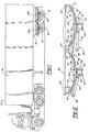
- tractor-trailer 10 is shown. More particularly, tractor 12 is operatively coupled to trailer 14 in a known manner for transporting a cargo (i.e. gas, building supplies, machinery, cement, etc.).
- Tractor-trailer 10 is exemplary in nature and is merely intended to illustrate one type of heavy-duty commercial transport vehicle to which the present invention is directed.
- Trailer 14 is shown to be of the tandem axle type, that is, the end of trailer 14 remote from tractor cab 12 is supported by one or more sets of front and rear wheels 16 and 18, respectively, which are rotatably mounted to front and rear axles 20 and 22, respectively, arranged one behind the other in a tandem relationship.
- a mechanical suspension system 24 is provided for damping relative movement between trailer 14 and axles 20 and 22.
- Figure 1 shows trailer 14 with its driver side suspension and wheels removed for providing a better view of mechanical suspension system 24.
- the present invention is directed to a unique dual-leaf tapered leaf spring assembly which is adapted for use with virtually any conventional trailer suspension system or axle arrangement of the type incorporating multi-leaf spring assemblies.
- Suspension system 24 is shown to include a pair of front leaf springs 26A (one on each side of trailer 14) and a pair of rear leaf springs 26B (one of each side of trailer 14) aligned in tandem relationship.
- front and rear springs 26A and 26B, respectively are substantial identical in configuration and operational characteristics.
- front and rear pairs of leaf springs 26A and 26B, respectively are adapted to be operably mounted between frame stringers 30 (frame stringers 30 are located on both sides of trailer 14) and their respective front and rear axles 20 and 22 for supporting and damping the relative movement therebetween.
- leaf springs 26A and 26B are shown as being connected at their mid-points to front and rear axes 20 and 22 in an "overslung” manner using conventional clamping means 32. More specifically, the connections are preferably identical for both front and rear springs 26A and 26B, respectively, with clamping means 32 comprised of a top clamp member 34 configured to embrace an inactive portion of the upper "tension" surface of main leaf 36 for leaf springs 26A and 26B.
- clamping means 32 comprised of a top clamp member 34 configured to embrace an inactive portion of the upper "tension" surface of main leaf 36 for leaf springs 26A and 26B.
- An upper face of a lower axle seat 38 engages a generally flat inactive portion of the lower "compression” surface 39 of a second leaf 40.
- the lower face of lower axle seat 38 is shaped complimentary to and engageable with its respective axle.
- a lower saddle clamp 42 is disposed below and matingly engages its respective axle.
- U-bolts 44 and torque nuts 45 are adapted to securely mount front and rear axles 20 and 22, respectively, to front and rear pairs of leaf springs 26A and 26B, respectively, in a known matter such that any movement of the axes causes a corresponding deflection or movement of leaf springs 26.
- Each front leaf spring 26A is supported between a front hanger bracket 46 and a center hanger bracket 48 which are both mounted to frame stringers 30.
- each rear leaf spring 26B is supported between central hanger bracket 48 and a rear hanger bracket 50.
- Front and rear hanger brackets 46 and 50 respectively, include bearing or cam pads 52 against which the outer non-adjacent ends of main leaf 36 for each of front and rear leaf springs 26A and 26B, respectively, are adapted to engage.
- front hanger brackets 46 and rear hanger brackets 50 are secured to the trailer's chassis frame stringers 30 at locations corresponding to the remote ends of leaf springs 26.
- An equalizer member 56 is supported within center hanger bracket 48 and includes a pair of similarly angled bearing pads 58 which are adapted for normal engagement with the inner adjacent ends of front and rear pairs of leaf springs 26A and 26B, respectively.
- Front, center and rear hanger brackets 46, 48 and 50, respectively, are generally inverted U-shaped structural members having downwardly extending side plates between which the respective leaf springs 26 and equalizer member 56 are disposed.
- front and rear hanger brackets 46 and 50, respectively are provided on opposite sides of trailer 14 and are fixedly interconnected via cross-support tubes 62 for providing structural rigidity.
- each equalizer member 56 is mounted inside its central hanger bracket 48 between its respective side plates and are fixedly interconnected via a cross-support tube 64 extending transversely between frame stringers 30.
- retainer tubes 66 and 68 extend transversely between the side plates of front and rear hanger brackets 46 and 50, respectively, and equalizer member 56 to inhibit dislocation of front and rear leaf springs 26A and 26B, respectively, and which are located beneath the ends of second leaf 40.
- a front torque rod 70 is connected between the side plates of front hanger bracket 46 and axle seat 38 of front leaf springs 26A while a second torque tube 72 is interconnected between the side plates of center hanger bracket 48 and spring seat 38 of rear leaf springs 26B.
- leaf springs 26 of the present invention is shown in a tandem axle arrangement it will be appreciated that leaf springs 26 can be installed in other suitable mechanical suspension systems and axle arrangements.
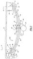
- leaf spring 26B includes first or main tapered leaf 36 having its opposite terminal end portions of its upper "tension” surface 69 in engagement with angled cam surface 70 of cam pad 52 and bearing pad 58 at positions outwardly of "roll-in” centerlines 72 and 74, respectively.
- the effective "active" length of main leaf 36 is at its greatest length when trailer 14 is at its “curb” loaded capacity.
- leaf spring 26B is deflected to the first stage "curb" loaded (i.e.
- trailer 14 is substantially unloaded) position.
- curb it is desirable to have a relatively low rate for a "soft" ride characteristic when trailer 14 is being transported in its substantially “unloaded” condition.
- the limited engagement of main leaf 36 with surface 70 of cam pad 52 and bearing pad 58 defines a "first stage” rate with ends 80 of second leaf 40 spaced below and disengaged therefrom.
- Each end 80 of second leaf 40 is cranked or slightly downturned to define a roll-in "contact” area specifically designed to engage the underside "compression" surface 82 of main leaf 36 upon continued axle deflection.
- one cranked end 80 of second leaf 40 terminates in a down-turned hook 83.
- each of first and second leafs 36 and 40 is formed to include a tapered thickness profile which effectively "approximates” a true modified parabolic surface and insures maintenance of interleaf gap 84.
- internal gap 84 provides the clearance necessary to promote smooth second leaf 40 to main leaf 36 engagement and roll-in without generating excessive interleaf contact or friction. As such, the present invention lends itself to low friction losses for keeping the potential energy (i.e. available damping) within the desired range of loaded and unloaded conditions.
- each of first and second leafs 36 and 40 are cambered to produce the generally semi-elliptical curvature shown from utilization of conventional hot forming and quenching processes.
- each of first and second leafs 36 and 40 respectively, has an "inactive" central clamped area of a predetermined length having spacers 86 disposed therebetween.
- a center bolt 88 passes through center bolt holes 90 punched in each leaf and a lock nut 92 is torqued thereon to rigidly clamp leafs 36 and 40 as dual-leaf spring assembly 26B.
- FIG. 4 various deflected positions of leaf spring 26B are shown. While these Figures are similar to Figure 3, they are intended to illustrate the "camming" action of both leafs upon continued axle displacement.
- second leaf 40 is sufficiently deflected until the contact areas on its outer most cranked end portions 80 on its upper tension surface 94 engage the underside "compression” surface 82 of main leaf 36 to initiate the rate transition from the lower first stage rate to a higher second stage rate ride characteristic.
- the present invention provides for a smooth non-linear transition which is generally parabolic in nature.
- crank ends 80 of second leaf 40 are adapted to "roll-in” from the "curb” position shown in Figure 3 to the initial contact position shown in Figure 4 with respect to centerlines 72 and 74 upon continued suspension deflection to provide a relatively long initial parabolic transition segment 100 (see Figure 6).
- This sliding or rolling action effectively shortens the "active" length or moment arm of second leaf 40.
- the loading thereon approaches the "design load” level, wherein tension surface 69 of main leaf 36 begins to "roll-in” on surface 70 of hanger cams 52 and 58 for effectively shortening the "active" length thereof so as to create a second parabolic transition portion 102 ( Figure 6).
- both main leaf 36 and second leaf 40 have effectively rolled in relative to centerlines 72 and 74.
- the tapered profiles of each leaf and the change in effective length act to produce a variable rate as shown at 104 in Figure 6.
- the various rate transition regions are best seen from the exemplary rate vs deflection curve of Figure 6 which shows the smooth and relatively long cumulative transition curve 106 of leaf spring 26B compared to the constant rate curve 108 for a conventional single-stage multi-leaf spring.
- tapered leaf springs provides superior volumetric material efficiency as compared to a conventional constant thickness multi-leaf spring assembly designed to provide similar operational characteristics.
- This volumetric efficiency defines the amount of potential energy which leaf spring 26B is capable of storing at a specified stress level relative to its volume of "active" material. Therefore, it is desireable to utilize a tapered leaf springs since they are more efficient and have a relatively constant stress distribution from its line of encasement (starting taper point 110 at end of the "clamped" area) to its point of load application.
- a schematic comparison is shown between a single linearly tapered thickness profile 112 and a true modified parabolic tapered profile 114 are shown.
- Each thickness profile begins tapering at point 110 from a starting thickness "t s " and terminates at a predetermined end thickness "t f ".
- Taper profile 114 is referred to as "modified” since a "true” parabolic taper decreased in thickness to zero thickness at the point of loading such that "t f " would equal zero.
- a modified parabolic taper includes an end portion of a known thickness "t f " for facilitating load application.
- a modified parabolic taper is an impractical design based on prohibitive production costs and manufacturing constraints.
- the present invention is directed at utilization of a tapered thickness profile which "approximates" a modified parabolic taper for maximum material efficiency at a realistic production cost.
- This profile is shown schematically at 116 in Figure 7.
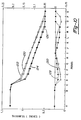
- exemplary approximated modified parabolic taper profiles of the type utilized in both of first and second leafs 36 and 40, respectively, are shown in Figure 8 and 9 which substantially replicate the true parabolic profile shown in Figure 7.
- the tapered profiles of first and second leafs 36 and 40 approximate or "track" a modified parabolic taper by incorporating a successive plurality of linearly tapered increments having distinct and different transition points. More particularly, according to the embodiment shown there are five transition points T1 through T5 for each leaf having an predetermined change in taper (inch per inch) which are specifically selected to minimize the material volume and achieve a higher and more uniform stress distribution throughout the entire leaf length.
- the initial quick taper (T1 to T2) allows the working stress from each leaf to be transferred more uniformly to inhibit premature stress-related failure in the center clamp area.
- Tables 1 through 4 list transitional taper information and point thickness information for leaf members 36 and 40 for leaf spring 26B.
- the specific modified parabolic taper profile for second leaf 40 is independent of and different than the modified parabolic taper profile for first main leaf 36. This is done to provide a higher working stress level in main leaf 36.
- Table 1 provides the incremental tapers for one-half of main leaf 36 (the other half being identical).
- Table 2 provides the incremental tapers for one-half of second leaf 40 shown in Figure 9.
- TABLE 2 TRANSITION DATA - SECOND LEAF TRANSITION POINTS INCREMENTAL TAPER (INCH/INCH) T1 TO T2 .220 T2 TO T3 .039 T3 TO T4 .045 T4 TO T5 .053
- curve 120 represents the modified parabolic taper profile of main leaf 36
- curve 122 represents a constant linear taper profile comparison
- curve 124 represents the modified parabolic taper profile of second leaf 40
- curve 126 designates its corresponding comparative constant linear taper.
- curves 120 and 124 closely "track" the true modified taper shown in Figure 7.
- the difference information listed in Tables 3 and 4, and represented in plots 128 and 130 of Figure 10, show the substantial impact the modified taper profile has on material utilization and working stresses relative to a constant linear taper.
- a taper rolling apparatus 200 includes a vertically movable roll 202 and a horizontally movable carriage 204.
- Left and right cam dies 206 are securely afixed to a top surface 208 of carriage 204 in a predetermined spaced relationship adapted to permit one or more pieces of constant thickness bar stock 210 to be disposed therebetween.
- Cam dies 206 are cut to include a cammed rolling surface 212 which corresponds to the desired approximated modified parabolic taper.
- cam profile dies 206 are designed to compensate for thermal shrinkage of bar stock 210 following the hot taper rolling process.
- constant thickness bar stock 210 is heated to a predetermined elevated temperature and is located between cam profile dies 206.
- Carriage 204 is then moved into a position such that roll 202 die may be lowered into engagement with a generally linear roll start surface 214 of cam profile dies 206.
- roll 202 is rotatably driven concurrently with the horizontal movement of carriage 204 to cause roll 202 to follow the contour of cam die 206.
- a majority of the material flow is in a lengthwise direction.
- the number of "passes" or rolling operations required for roll 202 to completely follow the entire cam die surface 212 is dependent on the severity and length of the taper desired.
- the second half of bar stock 210 is tapered (rolled) in a similar manner. Following the tapering operation, the tapered leafs 36 and 40 are reheated, hot formed and then quenched to the desired semi-elliptical curvature.
- the hot forming operations are adapted to provide cranked ends 80 and hook 90 on second leaf 40.
Landscapes
- Engineering & Computer Science (AREA)
- Mechanical Engineering (AREA)
- Springs (AREA)
- Vehicle Body Suspensions (AREA)
- Vibration Prevention Devices (AREA)
Applications Claiming Priority (2)
| Application Number | Priority Date | Filing Date | Title |
|---|---|---|---|
| US07/667,524 US5209518A (en) | 1991-03-11 | 1991-03-11 | Dual-stage tapered leaf spring for a trailer |
| US667524 | 1996-06-19 |
Publications (2)
| Publication Number | Publication Date |
|---|---|
| EP0503754A1 true EP0503754A1 (de) | 1992-09-16 |
| EP0503754B1 EP0503754B1 (de) | 1995-05-31 |
Family
ID=24678565
Family Applications (1)
| Application Number | Title | Priority Date | Filing Date |
|---|---|---|---|
| EP92300263A Revoked EP0503754B1 (de) | 1991-03-11 | 1992-01-13 | Zwei-stufiger verjüngte Blattfeder-Aufbau |
Country Status (10)
| Country | Link |
|---|---|
| US (1) | US5209518A (de) |
| EP (1) | EP0503754B1 (de) |
| JP (1) | JPH05172170A (de) |
| KR (1) | KR920017858A (de) |
| AU (1) | AU650942B2 (de) |
| CA (1) | CA2059252C (de) |
| DE (1) | DE69202712D1 (de) |
| MX (1) | MX9200556A (de) |
| NZ (1) | NZ241298A (de) |
| TW (1) | TW221396B (de) |
Cited By (1)
| Publication number | Priority date | Publication date | Assignee | Title |
|---|---|---|---|---|
| EP1138432A3 (de) * | 2000-03-25 | 2002-07-31 | Tinsley Bridge Limited | Aufhängungslenker für ein Kraftfahrzeug und Verfahren zur dessen Herstellung |
Families Citing this family (28)
| Publication number | Priority date | Publication date | Assignee | Title |
|---|---|---|---|---|
| US5265308A (en) * | 1990-12-19 | 1993-11-30 | Intek Weatherseal Products, Inc. | Jamb liner |
| SE503443C2 (sv) * | 1992-12-22 | 1996-06-17 | Volvo Ab | Bladfjäder för upphängning av en stel hjulaxel hos ett fordon |
| MXPA95001464A (es) * | 1994-03-22 | 2010-10-04 | Tradesman Ind Inc | Vehiculo mejorado. |
| US5730427A (en) * | 1996-03-28 | 1998-03-24 | Dana Corporation | Trailer spring assembly |
| US6679517B2 (en) * | 1998-08-24 | 2004-01-20 | Cataldo Proia | Retrofit suspension system for a vehicle |
| US6431564B1 (en) * | 1998-08-24 | 2002-08-13 | Cataldo Proia | Add-on self tracking axle for a vehicle |
| US6406007B1 (en) * | 2000-03-10 | 2002-06-18 | The Boler Company | Leaf spring assembly having full-leaf leaf spring component and half-leaf leaf spring component |
| US7195272B2 (en) * | 2003-04-08 | 2007-03-27 | Freightliner Llc | Front-axle spring pivot suspension and steering apparatus |
| SE527371C2 (sv) * | 2003-04-24 | 2006-02-21 | Volvo Lastvagnar Ab | Hjulupphängning för fordon samt fordon försett med sådan hjulupphängning |
| US7213825B2 (en) * | 2004-02-12 | 2007-05-08 | Deere & Company | Leaf spring retaining bracket |
| JP2005344747A (ja) * | 2004-05-31 | 2005-12-15 | Koyo Seiko Co Ltd | 動力伝達シャフト |
| US7789378B2 (en) * | 2004-09-21 | 2010-09-07 | Dittmar Edbert E L | Plate spring with adjustable support cam |
| JP4640418B2 (ja) * | 2007-08-01 | 2011-03-02 | 日産自動車株式会社 | リーフスプリングの支持構造 |
| JP5367466B2 (ja) * | 2009-06-09 | 2013-12-11 | 日本車輌製造株式会社 | タンクトレーラ |
| US20110127753A1 (en) * | 2009-11-04 | 2011-06-02 | Jack Griffin | Leaf spring assembly and tandem suspension system |
| US8540263B2 (en) * | 2011-09-21 | 2013-09-24 | Suspensys Sistemas Automotivos Ltda. | Rear bogie-type suspension |
| CN104080626B (zh) * | 2012-01-31 | 2016-08-24 | 沃尔沃拉斯特瓦格纳公司 | 包括轻量板簧组件的车辆悬架 |
| AT513234B1 (de) * | 2012-07-30 | 2019-04-15 | Hendrickson Comm Vehicle Sys Europe Gmbh | Profilstab und daraus hergestelle Fahrzeugfeder |
| US9050873B2 (en) * | 2012-08-06 | 2015-06-09 | Hendrickson Usa, L.L.C. | Suspension system having a leaf spring |
| US10136472B2 (en) * | 2012-08-07 | 2018-11-20 | Plansee Se | Terminal for mechanical support of a heating element |
| BR102012031693A2 (pt) * | 2012-12-12 | 2014-09-02 | Suspensys Sist S Automotivos Ltda | Suportes centrais e balancins para suspensão tandem |
| JP6401506B2 (ja) * | 2014-06-11 | 2018-10-10 | 日野自動車株式会社 | 車両のリヤサスペンション構造 |
| WO2018013659A1 (en) * | 2016-07-15 | 2018-01-18 | Stalwart Design & Development LLC | Tandem axle suspension system with fixed keeper and slipper springs |
| DE102017218530B4 (de) * | 2017-10-17 | 2021-05-27 | Ford Global Technologies, Llc | Längsblattfedervorrichtung zur Federung einer Kraftfahrzeugkarosserie |
| BE1027804B1 (nl) * | 2019-12-20 | 2021-11-08 | Bcw Nv | Aanhangwagen |
| JP7687981B2 (ja) * | 2022-03-18 | 2025-06-03 | 日本発條株式会社 | 板ばね装置および電力変換装置 |
| US12187092B2 (en) | 2022-08-11 | 2025-01-07 | Rv Ride Control, Llc | Tandem axle suspension system with keeper having sliding slipper blocks |
| US12311714B1 (en) | 2024-05-31 | 2025-05-27 | Ford Global Technologies, Llc | Tension leaf with auxiliary spring |
Citations (9)
| Publication number | Priority date | Publication date | Assignee | Title |
|---|---|---|---|---|
| US3672656A (en) * | 1969-08-01 | 1972-06-27 | Nissan Motor | Multi-leaf spring for automotive suspension |
| US3945625A (en) * | 1972-05-29 | 1976-03-23 | Ressorts Du Nord S. A. | Leaf spring |
| DE2349381B2 (de) * | 1972-10-03 | 1979-05-10 | Jonas Woodhead Ltd., Leeds, Yorkshire (Grossbritannien) | Blattfeder |
| GB2056015A (en) * | 1979-08-14 | 1981-03-11 | Nhk Spring Co Ltd | Laminated Leaf Spring with Spaces Between the Leaves |
| DE3035915A1 (de) * | 1980-09-24 | 1982-04-08 | Volkswagenwerk Ag, 3180 Wolfsburg | Blattfederanordnung, insbesondere fuer die abfederung von kraftfahrzeugen |
| FR2526110A2 (fr) * | 1982-02-19 | 1983-11-04 | Allevard Ind Sa | Ressorts a lames paraboliques comportant des dispositifs amortisseurs |
| GB2157393A (en) * | 1984-04-11 | 1985-10-23 | British Steel Corp | Improvements in and relating to leaf spring assemblies |
| GB2185088A (en) * | 1986-01-07 | 1987-07-08 | Mitsubishi Steel Mfg | A suspension system for vehicles |
| US4750718A (en) * | 1985-09-05 | 1988-06-14 | A. O. Smith Corporation | Dual rate leaf spring construction |
Family Cites Families (13)
| Publication number | Priority date | Publication date | Assignee | Title |
|---|---|---|---|---|
| US1233762A (en) * | 1916-03-03 | 1917-07-17 | William F Doherty Jr | Vehicle-spring. |
| US1221109A (en) * | 1916-07-12 | 1917-04-03 | Phenno L Titus | Vehicle-spring. |
| US1391644A (en) * | 1920-02-13 | 1921-09-20 | Rosco S Threlkeld | Vehicle-spring |
| US1551612A (en) * | 1923-09-24 | 1925-09-01 | Elmer H Oversmith | Vehicle spring |
| US2533511A (en) * | 1945-11-29 | 1950-12-12 | Standard Steel Spring Co | Single-leaf vehicle spring |
| US3079139A (en) * | 1960-04-20 | 1963-02-26 | Rockwell Standard Co | Tapered spring leaf |
| US3580347A (en) * | 1967-12-13 | 1971-05-25 | Dura Corp | Tapered spring leaf suspension for driver tandem axle assembly |
| GB1337558A (en) * | 1972-10-24 | 1973-11-14 | Crane Fruehauf Trailers Ltd | Tandem axle suspension |
| US3833236A (en) * | 1973-07-16 | 1974-09-03 | A J Ind Inc | Equalized suspension system for a tandem axle vehicle |
| US3933367A (en) * | 1974-07-03 | 1976-01-20 | Dura Corporation | Dual leaf spring suspension |
| JPS5711102A (en) * | 1980-06-25 | 1982-01-20 | Mitsubishi Steel Mfg Co Ltd | Suspension device for vehicle |
| JPS5834690B2 (ja) * | 1981-02-18 | 1983-07-28 | 日本発条株式会社 | 重ね板ばね装置 |
| JPH01501381A (ja) * | 1986-11-28 | 1989-05-18 | キエフスキー、インゼネルノ―ストロイチェルヌイ、インスチツート | 車両の弾性的懸架装置 |
-
1991
- 1991-03-11 US US07/667,524 patent/US5209518A/en not_active Expired - Lifetime
-
1992
- 1992-01-13 CA CA002059252A patent/CA2059252C/en not_active Expired - Fee Related
- 1992-01-13 EP EP92300263A patent/EP0503754B1/de not_active Revoked
- 1992-01-13 DE DE69202712T patent/DE69202712D1/de not_active Expired - Lifetime
- 1992-01-14 NZ NZ241298A patent/NZ241298A/en unknown
- 1992-01-14 AU AU10230/92A patent/AU650942B2/en not_active Ceased
- 1992-02-10 MX MX9200556A patent/MX9200556A/es unknown
- 1992-02-10 TW TW081100899A patent/TW221396B/zh active
- 1992-02-20 KR KR1019920002560A patent/KR920017858A/ko not_active Withdrawn
- 1992-02-21 JP JP4072775A patent/JPH05172170A/ja active Pending
Patent Citations (9)
| Publication number | Priority date | Publication date | Assignee | Title |
|---|---|---|---|---|
| US3672656A (en) * | 1969-08-01 | 1972-06-27 | Nissan Motor | Multi-leaf spring for automotive suspension |
| US3945625A (en) * | 1972-05-29 | 1976-03-23 | Ressorts Du Nord S. A. | Leaf spring |
| DE2349381B2 (de) * | 1972-10-03 | 1979-05-10 | Jonas Woodhead Ltd., Leeds, Yorkshire (Grossbritannien) | Blattfeder |
| GB2056015A (en) * | 1979-08-14 | 1981-03-11 | Nhk Spring Co Ltd | Laminated Leaf Spring with Spaces Between the Leaves |
| DE3035915A1 (de) * | 1980-09-24 | 1982-04-08 | Volkswagenwerk Ag, 3180 Wolfsburg | Blattfederanordnung, insbesondere fuer die abfederung von kraftfahrzeugen |
| FR2526110A2 (fr) * | 1982-02-19 | 1983-11-04 | Allevard Ind Sa | Ressorts a lames paraboliques comportant des dispositifs amortisseurs |
| GB2157393A (en) * | 1984-04-11 | 1985-10-23 | British Steel Corp | Improvements in and relating to leaf spring assemblies |
| US4750718A (en) * | 1985-09-05 | 1988-06-14 | A. O. Smith Corporation | Dual rate leaf spring construction |
| GB2185088A (en) * | 1986-01-07 | 1987-07-08 | Mitsubishi Steel Mfg | A suspension system for vehicles |
Cited By (1)
| Publication number | Priority date | Publication date | Assignee | Title |
|---|---|---|---|---|
| EP1138432A3 (de) * | 2000-03-25 | 2002-07-31 | Tinsley Bridge Limited | Aufhängungslenker für ein Kraftfahrzeug und Verfahren zur dessen Herstellung |
Also Published As
| Publication number | Publication date |
|---|---|
| AU1023092A (en) | 1992-09-17 |
| EP0503754B1 (de) | 1995-05-31 |
| AU650942B2 (en) | 1994-07-07 |
| DE69202712D1 (de) | 1995-07-06 |
| CA2059252C (en) | 2004-07-13 |
| NZ241298A (en) | 1994-06-27 |
| MX9200556A (es) | 1992-09-01 |
| JPH05172170A (ja) | 1993-07-09 |
| TW221396B (de) | 1994-03-01 |
| CA2059252A1 (en) | 1992-09-12 |
| US5209518A (en) | 1993-05-11 |
| KR920017858A (ko) | 1992-10-21 |
Similar Documents
| Publication | Publication Date | Title |
|---|---|---|
| EP0503754B1 (de) | Zwei-stufiger verjüngte Blattfeder-Aufbau | |
| AU656500B2 (en) | Service-life, low-profile, retrofittable, elastomeric mounting for three-piece, railroad-car trucks | |
| AU701489B2 (en) | Bellows, as well as air suspension system and axle lift system | |
| US4685174A (en) | Shock absorbing caster wheel suspension with frictional vertical oscillation dampening | |
| US10569814B2 (en) | Lift axle auxiliary suspension systems | |
| US6752406B2 (en) | Highway/rail trailer axle/suspension lift assembly | |
| US5368324A (en) | Mounting system for fifth wheels | |
| US20190061847A1 (en) | Tandem lift auxiliary axle assembly | |
| AU2002307353A1 (en) | Lift axle suspension | |
| US20060103103A1 (en) | Lightweight, low part-count, suspension system for wheeled vehicles | |
| LT3580B (en) | A guiding system applicable to a four-wheel bogie with variable gap between them | |
| CN113428232A (zh) | 一种弹性元件可切换式悬架总成及控制方法 | |
| US3664681A (en) | Air spring mounting for pickup trucks | |
| CA2485811A1 (en) | Multi-piece axle and suspension | |
| CN115023383B (zh) | 牵引联接器和轨道车辆 | |
| US11813918B2 (en) | Axle/suspension system for heavy-duty vehicles | |
| US2952455A (en) | Spring suspension for vehicles | |
| CN215720424U (zh) | 一种变刚度复合板簧结构 | |
| US2819910A (en) | Tandem vehicle wheel suspension | |
| EP1866184B1 (de) | Fahrzeugkarosserie mit einem gekrümmten metallplattenboden | |
| US20050263986A1 (en) | Tandem axle suspension assembly | |
| CN211032080U (zh) | 一种矿用自卸车橡胶副簧复合前悬架结构及矿用自卸车 | |
| CN113059973A (zh) | 一种组合式悬挂装置 | |
| Sternberg | Heavy-duty truck suspensions | |
| CN218257609U (zh) | 一种货车用轻型正装悬挂 |
Legal Events
| Date | Code | Title | Description |
|---|---|---|---|
| PUAI | Public reference made under article 153(3) epc to a published international application that has entered the european phase |
Free format text: ORIGINAL CODE: 0009012 |
|
| AK | Designated contracting states |
Kind code of ref document: A1 Designated state(s): DE ES FR GB IT |
|
| 17P | Request for examination filed |
Effective date: 19930120 |
|
| 17Q | First examination report despatched |
Effective date: 19940301 |
|
| GRAA | (expected) grant |
Free format text: ORIGINAL CODE: 0009210 |
|
| AK | Designated contracting states |
Kind code of ref document: B1 Designated state(s): DE ES FR GB IT |
|
| PG25 | Lapsed in a contracting state [announced via postgrant information from national office to epo] |
Ref country code: IT Free format text: LAPSE BECAUSE OF FAILURE TO SUBMIT A TRANSLATION OF THE DESCRIPTION OR TO PAY THE FEE WITHIN THE PRE;WARNING: LAPSES OF ITALIAN PATENTS WITH EFFECTIVE DATE BEFORE 2007 MAY HAVE OCCURRED AT ANY TIME BEFORE 2007. THE CORRECT EFFECTIVE DATE MAY BE DIFFERENT FROM THE ONE RECORDED.SCRIBED TIME-LIMIT Effective date: 19950531 Ref country code: FR Effective date: 19950531 |
|
| REF | Corresponds to: |
Ref document number: 69202712 Country of ref document: DE Date of ref document: 19950706 |
|
| PG25 | Lapsed in a contracting state [announced via postgrant information from national office to epo] |
Ref country code: DE Effective date: 19950901 Ref country code: ES Free format text: LAPSE BECAUSE OF FAILURE TO SUBMIT A TRANSLATION OF THE DESCRIPTION OR TO PAY THE FEE WITHIN THE PRESCRIBED TIME-LIMIT Effective date: 19950901 |
|
| EN | Fr: translation not filed | ||
| PGFP | Annual fee paid to national office [announced via postgrant information from national office to epo] |
Ref country code: GB Payment date: 19951228 Year of fee payment: 5 |
|
| PLBQ | Unpublished change to opponent data |
Free format text: ORIGINAL CODE: EPIDOS OPPO |
|
| PLBI | Opposition filed |
Free format text: ORIGINAL CODE: 0009260 |
|
| PLBF | Reply of patent proprietor to notice(s) of opposition |
Free format text: ORIGINAL CODE: EPIDOS OBSO |
|
| 26 | Opposition filed |
Opponent name: VERBAND DER DEUTSCHEN FEDERNINDUSTRIE -FAHRZEUGFED Effective date: 19960229 |
|
| PLBF | Reply of patent proprietor to notice(s) of opposition |
Free format text: ORIGINAL CODE: EPIDOS OBSO |
|
| PLBF | Reply of patent proprietor to notice(s) of opposition |
Free format text: ORIGINAL CODE: EPIDOS OBSO |
|
| RDAH | Patent revoked |
Free format text: ORIGINAL CODE: EPIDOS REVO |
|
| RDAG | Patent revoked |
Free format text: ORIGINAL CODE: 0009271 |
|
| GBPR | Gb: patent revoked under art. 102 of the ep convention designating the uk as contracting state |
Free format text: 961212 |
|
| 27W | Patent revoked |
Effective date: 19961212 |