EP0503544A2 - Dispositif de drainage automatique pour conteneurs à marchandises - Google Patents
Dispositif de drainage automatique pour conteneurs à marchandises Download PDFInfo
- Publication number
- EP0503544A2 EP0503544A2 EP92104023A EP92104023A EP0503544A2 EP 0503544 A2 EP0503544 A2 EP 0503544A2 EP 92104023 A EP92104023 A EP 92104023A EP 92104023 A EP92104023 A EP 92104023A EP 0503544 A2 EP0503544 A2 EP 0503544A2
- Authority
- EP
- European Patent Office
- Prior art keywords
- outer housing
- drainage device
- container
- valve cage
- wall
- Prior art date
- Legal status (The legal status is an assumption and is not a legal conclusion. Google has not performed a legal analysis and makes no representation as to the accuracy of the status listed.)
- Granted
Links
Images
Classifications
-
- B—PERFORMING OPERATIONS; TRANSPORTING
- B61—RAILWAYS
- B61D—BODY DETAILS OR KINDS OF RAILWAY VEHICLES
- B61D5/00—Tank wagons for carrying fluent materials
- B61D5/08—Covers or access openings; Arrangements thereof
-
- B—PERFORMING OPERATIONS; TRANSPORTING
- B65—CONVEYING; PACKING; STORING; HANDLING THIN OR FILAMENTARY MATERIAL
- B65D—CONTAINERS FOR STORAGE OR TRANSPORT OF ARTICLES OR MATERIALS, e.g. BAGS, BARRELS, BOTTLES, BOXES, CANS, CARTONS, CRATES, DRUMS, JARS, TANKS, HOPPERS, FORWARDING CONTAINERS; ACCESSORIES, CLOSURES, OR FITTINGS THEREFOR; PACKAGING ELEMENTS; PACKAGES
- B65D88/00—Large containers
- B65D88/74—Large containers having means for heating, cooling, aerating or other conditioning of contents
- B65D88/747—Large containers having means for heating, cooling, aerating or other conditioning of contents dehumidifying, dewatering or draining
-
- Y—GENERAL TAGGING OF NEW TECHNOLOGICAL DEVELOPMENTS; GENERAL TAGGING OF CROSS-SECTIONAL TECHNOLOGIES SPANNING OVER SEVERAL SECTIONS OF THE IPC; TECHNICAL SUBJECTS COVERED BY FORMER USPC CROSS-REFERENCE ART COLLECTIONS [XRACs] AND DIGESTS
- Y10—TECHNICAL SUBJECTS COVERED BY FORMER USPC
- Y10T—TECHNICAL SUBJECTS COVERED BY FORMER US CLASSIFICATION
- Y10T137/00—Fluid handling
- Y10T137/598—With repair, tapping, assembly, or disassembly means
- Y10T137/6031—Assembling or disassembling rotary valve
- Y10T137/6035—Rotary ball valve
-
- Y—GENERAL TAGGING OF NEW TECHNOLOGICAL DEVELOPMENTS; GENERAL TAGGING OF CROSS-SECTIONAL TECHNOLOGIES SPANNING OVER SEVERAL SECTIONS OF THE IPC; TECHNICAL SUBJECTS COVERED BY FORMER USPC CROSS-REFERENCE ART COLLECTIONS [XRACs] AND DIGESTS
- Y10—TECHNICAL SUBJECTS COVERED BY FORMER USPC
- Y10T—TECHNICAL SUBJECTS COVERED BY FORMER US CLASSIFICATION
- Y10T137/00—Fluid handling
- Y10T137/7287—Liquid level responsive or maintaining systems
- Y10T137/7313—Control of outflow from tank
- Y10T137/7316—Self-emptying tanks
- Y10T137/7319—By float
-
- Y—GENERAL TAGGING OF NEW TECHNOLOGICAL DEVELOPMENTS; GENERAL TAGGING OF CROSS-SECTIONAL TECHNOLOGIES SPANNING OVER SEVERAL SECTIONS OF THE IPC; TECHNICAL SUBJECTS COVERED BY FORMER USPC CROSS-REFERENCE ART COLLECTIONS [XRACs] AND DIGESTS
- Y10—TECHNICAL SUBJECTS COVERED BY FORMER USPC
- Y10T—TECHNICAL SUBJECTS COVERED BY FORMER US CLASSIFICATION
- Y10T137/00—Fluid handling
- Y10T137/7287—Liquid level responsive or maintaining systems
- Y10T137/7358—By float controlled valve
- Y10T137/7423—Rectilinearly traveling float
- Y10T137/7426—Float co-axial with valve or port
- Y10T137/7436—Float rigid with valve
Definitions
- the device works particularly trouble-free over a practically arbitrarily long operating time, it is easy to manufacture and assign to the respective container and it ensures that no more than a reasonable minimum amount of water accumulates in the container over a practically arbitrarily long operating time and, moreover, in one area in which the cargo is not normally located.
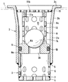
- the device according to the innovation is a structural unit which, as such, can be assigned in a simple manner to an essentially arbitrary container or container in such a way that it is inserted into the container floor and protrudes downwards, penetrating the container floor, from the container.
- the container floor is therefore only symbolically represented in the drawing by the dash-dot line 1.
- the device has an outer housing, which is composed of an outer housing upper part 2 and an outer housing lower part 3.
- Upper part 2 and lower part 3 are each a tube, the lower part being a smooth tube with a constant cross-section over the entire length, which is open at the end, which in the installed state is identified as the upper end facing the upper part 2, and at the other End, which in the installed state is identified as the lower end and is the end facing away from the upper part, has a cover 4.
- the upper part 2 is again a smooth pipe section 2a with a constant cross-section in the longer, lower and lower part 3, in relation to the installed state.
- a funnel-shaped pipe section 2b is attached at the top, which ends at the upper, further end in an outwardly directed fastening flange 2c.
- the inner cross section of the smooth tube section 2a is so much larger than the outer cross section of the lower tube 3 that the outer housing lower part 3 is axially aligned from below by a certain amount into the outer housing upper part 2, the outer housing lower part 3 after insertion into the outer housing upper part 2 is without play in this and both outer housing parts form a outer seam of the drainage device after applying a weld 5.
- the device With this outer housing, the device can be inserted into a corresponding opening in the container base from above until the outer housing rests with the underside of the radial flange 2c on the upper side of the container base 1, care being taken that suitable fastening means and suitable sealing means ensure that the device is assigned to the container in a fixed position and with the avoidance of leaks.
- the tube wall is provided with holes 6, just like the cover 4 welded (weld seam 7) to the tube which forms the outer housing lower part 3 is provided with such holes.
- the holes 6 are arranged in an appropriate pattern.
- the holes form two rows which are spaced apart in the longitudinal direction and within each row extending in the circumferential direction of the tube the holes are evenly spaced.
- the holes in the row closer to the lower pipe end are arranged so that the horizontal diameters lie in the plane of the pipe end, so that a regularly perforated peripheral edge is formed.
- a hole 6 is arranged concentrically in the lid 4 and around this hole are uniform on a circle near the outer periphery of the lid several of the holes 6 are spaced apart.
- a valve cage 8 is inserted into the upper housing part 2 from the upper end.
- the valve cage has a cylindrical foot 8a with a central through opening 20, the outer diameter of which corresponds to the inner diameter of the outer housing upper part 2 in the smooth section 2a, the upper inner circumference of which forms a valve seat 8b surrounding the opening 20.
- a circumferential groove 9 is provided, which receives a sealing ring 10, which lies with pretension between the walls of the outwardly open groove 9 and the inner wall of the section 2a of the upper housing part 2.
- the cylindrical portion 8c of the valve cage 8 adjoins the foot 8a between the outer and inner edge, the outer and inner diameters of which remain the same over the entire length.
- a cover 11 is inserted without play into the valve cage 8, which lies with the outer circumference of a short cylindrical section 11a with a slight press fit on the inner wall of section 8c of the valve cage 8 and with the underside of the radially lying flange or base 11b the upper end face of the cylindrical portion 8a of the valve cage 8 rests.
- the cover 11 of the valve cage lies on the inner surface of the funnel-shaped extension 2b of the outer housing upper part 2, the upper side of the flange 11b being located a predetermined amount below the radial flange 2c of the outer housing.
- the cylindrical section 8a of the valve cage 8 is provided with holes 12 which are at least approximately the same area as the holes 6 and are arranged in three approximately equally spaced circumferential rows with the same distances within each row. Such holes are also associated with the bottom or flange 11b of the cover 11 and are equally spaced in two concentric rows within the section 11a and in two concentric rows in the flange part outside the section 11a, it being harmless that the holes in the inner row in the Flange part outside of section 11a are partially covered by the upper end face of cylinder section 8c of valve body 8.
- a floating valve member 14 as a closing member, which has the shape of a ball and whose lower end position is determined by the valve seat 8b and whose upper end position is determined by the bottom 11b of the cover 11 of the valve cage 8.
- the outer housing 2, 3 with its cover 4 and the valve cage 8 with its cover 11 are made of a non-rusting metal, although a plastic is not excluded.
- the valve member 14 is made of a material which ensures that the valve member 14 is seated on the valve seat when it is surrounded by air, but which ensures that the valve member 14 floats and lifts off the valve seat 8b when the valve member is at a predetermined level from below Water is surrounded.
- the valve member 14 is seated on the valve seat 8b, contours and contact pressure block the container interior and the container environment from one another and, if the container is leakproof, the air-conditioning capability of the container interior is not impaired.
- condensation water begins to form in the container, it gets into the outer housing 2, 3, it collects over the sealing ring 10, is distributed evenly over the interior 13 enclosed by the valve basket 8 and the annular space between the valve basket and the outer housing.
- the contact pressure with which the valve member 14 is held on the valve seat 8b decreases, but this is not harmful because the water surrounding the contact area acts like a seal.
- valve member 14 causes the valve member 14 to lift off the valve seat 8b and the pent-up water can flow outwards until the initial state is reached, i.e. the valve member 14 rests on the valve seat 8b.
- the device can be assembled and installed from simple parts in a simple manner, so it causes low manufacturing and installation costs. It has practically no wear parts, so it will be able to work reliably over a long period of use. It is easy to clean by inserting a sharp jet of water from below, which can be used to detach and rinse out contaminants that may have accumulated. For more intensive cleaning, the valve cage 8 with the cover 11 and the valve member 14 can be removed by simply pulling it upward out of the outer housing.
- the lid 11 which is provided with holes, allows the water to be removed from the container to enter the valve chamber via the web 8a, but on the other hand, as a sieve, keeps coarse contaminants from the interior of the container away from the area of interaction of the valve seat 8b and valve member 14.
- the holes 6 in the lower end of the housing allow the water to be removed from the container to escape, but sieve-like prevent the entry of contaminants from the vicinity of the container into the region of the interaction of the valve seat 8b and the valve member 14.
- the subject of the innovation can be characterized as follows and with its essential features.
- An outer housing (2, 3) which can be inserted into the container bottom is divided into two chambers by a web (8a), one of which is connected to the inside of the container, the other to the surroundings of the container.
- the web encloses an opening (20) which connects the two chambers to one another when a valve member (14) has moved away from a seat (8b) surrounding the opening. If the valve member sits on the seat, the chambers are separated from one another and the interior of the container is not connected to the surroundings of the container.
- the movement of the valve member is controlled by the water level in the chamber, which communicates with the interior of the container.
- the device is used for the automatic drainage of containers. Your specific characteristics result from the following claims.
Landscapes
- Engineering & Computer Science (AREA)
- Mechanical Engineering (AREA)
- Transportation (AREA)
- Packages (AREA)
- Closures For Containers (AREA)
Applications Claiming Priority (2)
| Application Number | Priority Date | Filing Date | Title |
|---|---|---|---|
| DE9102782U DE9102782U1 (fr) | 1991-03-08 | 1991-03-08 | |
| DE9102782U | 1991-03-08 |
Publications (3)
| Publication Number | Publication Date |
|---|---|
| EP0503544A2 true EP0503544A2 (fr) | 1992-09-16 |
| EP0503544A3 EP0503544A3 (en) | 1993-03-10 |
| EP0503544B1 EP0503544B1 (fr) | 1996-11-27 |
Family
ID=6865042
Family Applications (1)
| Application Number | Title | Priority Date | Filing Date |
|---|---|---|---|
| EP92104023A Expired - Lifetime EP0503544B1 (fr) | 1991-03-08 | 1992-03-09 | Dispositif de drainage automatique pour conteneurs à marchandises |
Country Status (6)
| Country | Link |
|---|---|
| US (1) | US5201340A (fr) |
| EP (1) | EP0503544B1 (fr) |
| JP (1) | JP3353908B2 (fr) |
| KR (1) | KR960003298Y1 (fr) |
| DE (2) | DE9102782U1 (fr) |
| ES (1) | ES2095342T3 (fr) |
Cited By (1)
| Publication number | Priority date | Publication date | Assignee | Title |
|---|---|---|---|---|
| RU2683364C2 (ru) * | 2013-01-11 | 2019-03-28 | Сэн-Гобэн Изовер | Теплоизоляционный продукт на основе минеральной ваты и способ получения продукта |
Families Citing this family (30)
| Publication number | Priority date | Publication date | Assignee | Title |
|---|---|---|---|---|
| DE19649864A1 (de) * | 1996-12-02 | 1998-06-04 | Graaff Vertriebs Gmbh | Selbsttätige Entwässerungsvorrichtung für Frachtcontainer oder andere Ladungen aufnehmende Räume |
| US5799504A (en) * | 1996-12-04 | 1998-09-01 | White Consolidated Industries, Inc. | Refrigerator system with float valve flow control |
| KR19980087630A (ko) * | 1998-09-03 | 1998-12-05 | 김종선 | 하수구의 악취 및 하수역류 차단장치 |
| US6209570B1 (en) | 1999-04-21 | 2001-04-03 | Munters Corporation | Automatic flush valve |
| DE20003655U1 (de) * | 2000-02-28 | 2001-07-12 | Passavant Roediger Umwelttech | Bodenablauf mit Schwimmerverschluß |
| JP4614729B2 (ja) * | 2004-10-15 | 2011-01-19 | コンドーエフアルピー工業株式会社 | 排水トラップ |
| PL1683742T3 (pl) * | 2005-01-22 | 2007-09-28 | Waggonbau Graaff Gmbh | Zawór do odwadniania kontenerów frachtowych i tym podobnych |
| KR100713015B1 (ko) * | 2006-03-29 | 2007-05-04 | 영봉 강 | 씽크대용 배수장치 |
| EP2562465A1 (fr) * | 2011-08-23 | 2013-02-27 | Yu Shen Machinery Co., Ltd. | Purgeur automatique de débit de vapeur |
| EP2743412B1 (fr) * | 2012-12-11 | 2015-11-18 | Khaled Jafar Al-Hasan | Ensemble de drain |
| CN103478035A (zh) * | 2013-09-12 | 2014-01-01 | 青岛海琛网箱科技有限公司 | 一种养殖网箱浮力立管充气排水防涡流装置 |
| JP6293536B2 (ja) * | 2014-03-18 | 2018-03-14 | 大和製罐株式会社 | ポンプ容器 |
| DE102014220811B4 (de) * | 2014-10-14 | 2023-02-16 | Elringklinger Ag | Drainagevorrichtung |
| US10570594B2 (en) | 2017-03-21 | 2020-02-25 | Juka Innovations Corporation | Hair straining device |
| US10344460B2 (en) | 2015-09-16 | 2019-07-09 | Juka Innovations Corporation | Hair straining device |
| US10106967B2 (en) * | 2015-11-10 | 2018-10-23 | Joseph A. Sebolt | Removable hinged strainer for a pop-up drain assembly |
| CN105276370A (zh) * | 2015-11-17 | 2016-01-27 | 江苏中一节能科技股份有限公司 | 水蒸气离心压缩机机壳自动排水装置 |
| US10451307B2 (en) | 2016-04-15 | 2019-10-22 | Hoffman Enclosures, Inc. | Float drain |
| EP3338033B1 (fr) * | 2016-08-14 | 2020-02-19 | Deschamps, Nicholas Howard | Dispositifs permettant de prendre en charge un condensat |
| BG67081B1 (bg) * | 2016-09-26 | 2020-06-15 | Александрова Стефанова Елена | Самозатваряща обратна клапа за пълно спиране на възвратен въздушен поток през вентилационни устройства и съоръжения |
| USD794759S1 (en) | 2017-03-21 | 2017-08-15 | Juka Innovations Corporation | Strainer device for a drain |
| US10082213B1 (en) * | 2017-07-13 | 2018-09-25 | Alvin J. Character | Check valve floor drain |
| CN107559578B (zh) * | 2017-10-25 | 2019-10-25 | 泉州市念芝工业设计有限公司 | 一种自动真空排水装置 |
| CN111373211B (zh) | 2017-11-02 | 2022-08-12 | 庆东纳碧安株式会社 | 凝结水捕集装置 |
| DE102018007379A1 (de) * | 2018-09-19 | 2020-03-19 | FRÖTEK Vermögensverwaltung GmbH | Schwimmerventil |
| JP7181751B2 (ja) * | 2018-10-10 | 2022-12-01 | 株式会社テイエルブイ | フロート式逆流防止弁 |
| JP7092640B2 (ja) * | 2018-10-25 | 2022-06-28 | 株式会社テイエルブイ | フロート式逆止弁 |
| US11060786B1 (en) | 2019-10-14 | 2021-07-13 | Nicholas Howard Des Champs | Systems, devices, and/or methods for managing condensate |
| US11231203B1 (en) | 2021-02-23 | 2022-01-25 | Nicholas H. Des Champs | Systems, devices, and/or methods for managing condensate |
| US11808482B1 (en) | 2023-06-30 | 2023-11-07 | Des Champs Technologies Llc | Systems, devices, and/or methods for managing condensate |
Citations (3)
| Publication number | Priority date | Publication date | Assignee | Title |
|---|---|---|---|---|
| US3903918A (en) * | 1974-08-19 | 1975-09-09 | Clarence L Carnarius | Drain with check valve |
| US3921663A (en) * | 1972-09-11 | 1975-11-25 | Ceskoslovenska Akademie Ved | Cap for inlet of fluid into a fluidized bed |
| US4314583A (en) * | 1980-06-09 | 1982-02-09 | Peterson Harold A | Backwater valve |
Family Cites Families (10)
| Publication number | Priority date | Publication date | Assignee | Title |
|---|---|---|---|---|
| US914418A (en) * | 1908-04-21 | 1909-03-09 | Ira Hutchins | Automatic valve for steam-radiators. |
| US921865A (en) * | 1908-05-04 | 1909-05-18 | Edward Miller | Steam-trap. |
| US1623515A (en) * | 1926-12-02 | 1927-04-05 | Workman John Elmer | Trap |
| US1982555A (en) * | 1934-03-05 | 1934-11-27 | Horst Henry Van Der | Plumbing fixture |
| US2199673A (en) * | 1938-04-25 | 1940-05-07 | Ronning Adolph | Drain |
| US2787376A (en) * | 1954-09-13 | 1957-04-02 | Coulson Walter | Automatic check valve for drain pipe |
| US2972412A (en) * | 1955-03-25 | 1961-02-21 | Stanley A Lundeen | Float valve and strainer |
| US3759281A (en) * | 1971-11-19 | 1973-09-18 | Grupul Ind Pentru Foraj Si Ext | Cementing float shoe |
| US4132238A (en) * | 1977-04-29 | 1979-01-02 | Clark Earl A | Automatic separator valve |
| US4742842A (en) * | 1986-02-03 | 1988-05-10 | Hamlet & Garneau Inc. | Hydro-pneumatic pressure vessels |
-
1991
- 1991-03-08 DE DE9102782U patent/DE9102782U1/de not_active Expired - Lifetime
-
1992
- 1992-03-03 US US07/844,841 patent/US5201340A/en not_active Expired - Lifetime
- 1992-03-05 JP JP04835392A patent/JP3353908B2/ja not_active Expired - Fee Related
- 1992-03-07 KR KR92003646U patent/KR960003298Y1/ko not_active IP Right Cessation
- 1992-03-09 DE DE59207565T patent/DE59207565D1/de not_active Expired - Fee Related
- 1992-03-09 EP EP92104023A patent/EP0503544B1/fr not_active Expired - Lifetime
- 1992-03-09 ES ES92104023T patent/ES2095342T3/es not_active Expired - Lifetime
Patent Citations (3)
| Publication number | Priority date | Publication date | Assignee | Title |
|---|---|---|---|---|
| US3921663A (en) * | 1972-09-11 | 1975-11-25 | Ceskoslovenska Akademie Ved | Cap for inlet of fluid into a fluidized bed |
| US3903918A (en) * | 1974-08-19 | 1975-09-09 | Clarence L Carnarius | Drain with check valve |
| US4314583A (en) * | 1980-06-09 | 1982-02-09 | Peterson Harold A | Backwater valve |
Cited By (2)
| Publication number | Priority date | Publication date | Assignee | Title |
|---|---|---|---|---|
| RU2683364C2 (ru) * | 2013-01-11 | 2019-03-28 | Сэн-Гобэн Изовер | Теплоизоляционный продукт на основе минеральной ваты и способ получения продукта |
| RU2764087C2 (ru) * | 2013-01-11 | 2022-01-13 | Сэн-Гобэн Изовер | Теплоизоляционный продукт на основе минеральной ваты и способ получения продукта |
Also Published As
| Publication number | Publication date |
|---|---|
| KR960003298Y1 (ko) | 1996-04-19 |
| ES2095342T3 (es) | 1997-02-16 |
| JPH0680192A (ja) | 1994-03-22 |
| EP0503544B1 (fr) | 1996-11-27 |
| JP3353908B2 (ja) | 2002-12-09 |
| DE9102782U1 (fr) | 1991-06-27 |
| US5201340A (en) | 1993-04-13 |
| KR920018092U (ko) | 1992-10-17 |
| DE59207565D1 (de) | 1997-01-09 |
| EP0503544A3 (en) | 1993-03-10 |
Similar Documents
| Publication | Publication Date | Title |
|---|---|---|
| EP0503544A2 (fr) | Dispositif de drainage automatique pour conteneurs à marchandises | |
| DE3117528A1 (de) | Ventil fuer viehtraenkeinrichtung | |
| DE19828328C2 (de) | Stopfenanordnung zum Verschließen von Löchern in der Karosserie von Fahrzeugen | |
| DE19826959A1 (de) | Druckspülsystem | |
| CH633081A5 (de) | Oelbehaelter. | |
| DE19649864A1 (de) | Selbsttätige Entwässerungsvorrichtung für Frachtcontainer oder andere Ladungen aufnehmende Räume | |
| DE2222917A1 (de) | Behaelter fuer schildkroeten | |
| DE1968897U (de) | Ventil fuer die trinkwasserversorgung fuer gefluegel. | |
| DE19741827B4 (de) | Ablaufarmatur für Bade- oder Duschwannen | |
| EP0554884B1 (fr) | Soupape d'abreuvoir pour petits animaux | |
| DE4424575A1 (de) | Entgasungsventil | |
| DE2901402A1 (de) | Traenkanlage fuer kleintiere, insbesondere ferkel und gefluegel | |
| WO2009056277A1 (fr) | Soupape à double siège avec possibilité de nettoyage de siège et procédé de nettoyage de cette soupape | |
| DE2455628A1 (de) | Dampfkondensator | |
| DE2309774B2 (de) | Vorrichtung zum Tränken von Tieren, insbesondere von Geflügel | |
| DE2800556A1 (de) | Ventil zur entlueftung und belueftung insbesondere einer abwasserleitung | |
| DE1812592B2 (de) | Vorrichtung zum selbsttätigen Ent leeren von Kondensat aus Druckluft speicherbehaltern mit einer Druckkammer | |
| DE2530270A1 (de) | Vorrichtung zur kontaktgabe zwischen einer fluessigkeit und einem gas | |
| DE1609199A1 (de) | Brausekopf | |
| DE2650655A1 (de) | Rohrunterbrecher | |
| DE2020610A1 (de) | Vorrichtung zum Belueften und Verhindern des Rueckflusses | |
| DE2646259C3 (de) | Druckluftreiniger, insbesondere für Bremsanlagen von Kraftfahrzeugen | |
| DE3241044A1 (de) | Aufsetzbare abgiessvorrichtung fuer flaschen, insbesondere speiseoelflaschen | |
| DE2639962A1 (de) | Siphon fuer sanitaerobjekte | |
| DE19544984A1 (de) | Trag- und Führungsgruppe für ein Verschlußorgan eines Magnetventils |
Legal Events
| Date | Code | Title | Description |
|---|---|---|---|
| PUAI | Public reference made under article 153(3) epc to a published international application that has entered the european phase |
Free format text: ORIGINAL CODE: 0009012 |
|
| AK | Designated contracting states |
Kind code of ref document: A2 Designated state(s): DE ES GB IT |
|
| PUAL | Search report despatched |
Free format text: ORIGINAL CODE: 0009013 |
|
| AK | Designated contracting states |
Kind code of ref document: A3 Designated state(s): DE ES GB IT |
|
| RHK1 | Main classification (correction) |
Ipc: B65D 88/74 |
|
| 17P | Request for examination filed |
Effective date: 19930818 |
|
| 17Q | First examination report despatched |
Effective date: 19950515 |
|
| GRAG | Despatch of communication of intention to grant |
Free format text: ORIGINAL CODE: EPIDOS AGRA |
|
| GRAH | Despatch of communication of intention to grant a patent |
Free format text: ORIGINAL CODE: EPIDOS IGRA |
|
| GRAH | Despatch of communication of intention to grant a patent |
Free format text: ORIGINAL CODE: EPIDOS IGRA |
|
| GRAA | (expected) grant |
Free format text: ORIGINAL CODE: 0009210 |
|
| AK | Designated contracting states |
Kind code of ref document: B1 Designated state(s): DE ES GB IT |
|
| ITF | It: translation for a ep patent filed |
Owner name: SOCIETA' ITALIANA BREVETTI S.P.A. |
|
| REF | Corresponds to: |
Ref document number: 59207565 Country of ref document: DE Date of ref document: 19970109 |
|
| REG | Reference to a national code |
Ref country code: ES Ref legal event code: FG2A Ref document number: 2095342 Country of ref document: ES Kind code of ref document: T3 |
|
| GBT | Gb: translation of ep patent filed (gb section 77(6)(a)/1977) |
Effective date: 19970124 |
|
| PLBE | No opposition filed within time limit |
Free format text: ORIGINAL CODE: 0009261 |
|
| STAA | Information on the status of an ep patent application or granted ep patent |
Free format text: STATUS: NO OPPOSITION FILED WITHIN TIME LIMIT |
|
| 26N | No opposition filed | ||
| REG | Reference to a national code |
Ref country code: GB Ref legal event code: 732E |
|
| REG | Reference to a national code |
Ref country code: ES Ref legal event code: PC2A |
|
| REG | Reference to a national code |
Ref country code: GB Ref legal event code: IF02 |
|
| REG | Reference to a national code |
Ref country code: GB Ref legal event code: 732E |
|
| PGFP | Annual fee paid to national office [announced via postgrant information from national office to epo] |
Ref country code: ES Payment date: 20070416 Year of fee payment: 16 |
|
| PGFP | Annual fee paid to national office [announced via postgrant information from national office to epo] |
Ref country code: IT Payment date: 20070619 Year of fee payment: 16 |
|
| PGFP | Annual fee paid to national office [announced via postgrant information from national office to epo] |
Ref country code: GB Payment date: 20080225 Year of fee payment: 17 |
|
| REG | Reference to a national code |
Ref country code: ES Ref legal event code: FD2A Effective date: 20080310 |
|
| PG25 | Lapsed in a contracting state [announced via postgrant information from national office to epo] |
Ref country code: ES Free format text: LAPSE BECAUSE OF NON-PAYMENT OF DUE FEES Effective date: 20080310 |
|
| PG25 | Lapsed in a contracting state [announced via postgrant information from national office to epo] |
Ref country code: IT Free format text: LAPSE BECAUSE OF NON-PAYMENT OF DUE FEES Effective date: 20080309 |
|
| PGFP | Annual fee paid to national office [announced via postgrant information from national office to epo] |
Ref country code: DE Payment date: 20090327 Year of fee payment: 18 |
|
| GBPC | Gb: european patent ceased through non-payment of renewal fee |
Effective date: 20090309 |
|
| PG25 | Lapsed in a contracting state [announced via postgrant information from national office to epo] |
Ref country code: GB Free format text: LAPSE BECAUSE OF NON-PAYMENT OF DUE FEES Effective date: 20090309 |
|
| PG25 | Lapsed in a contracting state [announced via postgrant information from national office to epo] |
Ref country code: DE Free format text: LAPSE BECAUSE OF NON-PAYMENT OF DUE FEES Effective date: 20101001 |