EP0499249A2 - Verfahren zum Herstellen einer Halbleitervorrichtung mit einer Sperrschicht - Google Patents
Verfahren zum Herstellen einer Halbleitervorrichtung mit einer Sperrschicht Download PDFInfo
- Publication number
- EP0499249A2 EP0499249A2 EP92102410A EP92102410A EP0499249A2 EP 0499249 A2 EP0499249 A2 EP 0499249A2 EP 92102410 A EP92102410 A EP 92102410A EP 92102410 A EP92102410 A EP 92102410A EP 0499249 A2 EP0499249 A2 EP 0499249A2
- Authority
- EP
- European Patent Office
- Prior art keywords
- barrier layer
- oxide film
- film
- aluminum
- heat treatment
- Prior art date
- Legal status (The legal status is an assumption and is not a legal conclusion. Google has not performed a legal analysis and makes no representation as to the accuracy of the status listed.)
- Withdrawn
Links
Images
Classifications
-
- H10D64/011—
-
- H10P14/44—
-
- H10P95/00—
-
- H10W20/425—
-
- Y—GENERAL TAGGING OF NEW TECHNOLOGICAL DEVELOPMENTS; GENERAL TAGGING OF CROSS-SECTIONAL TECHNOLOGIES SPANNING OVER SEVERAL SECTIONS OF THE IPC; TECHNICAL SUBJECTS COVERED BY FORMER USPC CROSS-REFERENCE ART COLLECTIONS [XRACs] AND DIGESTS
- Y10—TECHNICAL SUBJECTS COVERED BY FORMER USPC
- Y10S—TECHNICAL SUBJECTS COVERED BY FORMER USPC CROSS-REFERENCE ART COLLECTIONS [XRACs] AND DIGESTS
- Y10S148/00—Metal treatment
- Y10S148/147—Silicides
Definitions
- the present invention relates to a semiconductor device comprising a barrier layer made of a high-melting point metal and provided between aluminum or aluminum alloy wiring and a silicon substrate.
- Thin films made of aluminum or aluminum-silicon or aluminum-copper alloys are mainly used as internal wiring materials for semiconductor devices.
- Al or an Al alloy is put into direct contact with a silicon substrate, interdiffusion between the wiring and the substrate is produced by heating in various subsequent steps, thus producing a problem with respect to the reliability of connection between the wiring and the substrate.
- a high-density semiconductor device comprising a thin impurity diffusion layer formed on a silicon substrate produces the critical problem that the thin impurity diffusion layer is damaged by such interdiffusion.
- a method is therefore employed in which a nitride film of a high-melting point metal such as titanium nitride (TiN) or the like is interposed as a barrier layer between aluminum or aluminum alloy wiring and a silicon substrate in order to inhibit interdiffusion between aluminum and the silicon substrate.
- TiN titanium nitride
- the interdiffusion between aluminum and the silicon substrate cannot be completely inhibited by such a barrier layer comprising a TiN thin film. It is thought that this is because Al atoms diffuse through the grain boundaries of microcrystals which constitute the TiN thin film.
- the TiN thin film is sometimes made ineffective as a barrier layer due to a decrease in the effective thickness thereof, which is caused by reaction between aluminum and the TiN thin film.
- a method is proposed in Japanese Patent Laid-Open No. 62-113421 in which a high-melting point metal film and a high-melting point metal nitride film are formed on a silicon substrate, and the surface of the metal nitride film is then thinly oxidized by heat treatment in an atmosphere of oxygen at 1 to 3 x 10 ⁇ 3 Torr. Namely, a thin oxide film is formed on the surface of the metal nitride film by heat treatment so that reaction of aluminum wiring with the high-melting point metal nitride film and the silicon substrate is inhibited.
- the above method requires an apparatus for heat treatment in an atmosphere of oxygen at low pressure.
- a mechanism for promoting cooling must be provided. This inevitably brings about the sacrifice of the throughput of the heat treatment step or an increase in the equipment cost.
- An embodiment of the present invention may provide a method which enables heat treatment for forming an oxide film on the surface of a barrier layer comprising a high-melting point metal nitride film to be performed without requiring a specified heat treatment apparatus and decreasing the throughput.
- the surface of a barrier layer formed on a silicon substrate and comprising, for example, a TiN film is oxidized by heating in a furnace atmosphere having substantially the same composition as that of air or immersing in an oxidizing chemical such as nitric acid to form an oxide film having a thickness of about 20 to 50 ⁇ thereon.
- a wiring layer made of aluminum, an aluminum alloy, tungsten, gold or copper is deposed on the barrier layer having the oxide film formed thereon.
- the oxide film comprises a TiN film containing titanium oxides such as TiO, TiO2 and the like. Even if such an oxide film is an insulator, when the oxide film has a thickness of 20 to 50 ⁇ or less, conductivity between the silicon substrate and the wiring layer is maintained due to the tunnel effect without any practical problem.
- the present invention requires no apparatus for heat treatment in a low-pressure oxygen atmosphere.
- the surface of the high-melting point metal film is mainly oxidized by heat treatment in an atmosphere having substantially the same composition as that of air or immersing in a chemical, the substance treated is hardly oxidized even if it is exposed to air. There is thus no need for a specific mechanism for cooling the substance treated, and a surface oxide film having a predetermined thickness and properties can be stably formed.
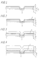
- an insulating layer 3 comprising an SiO2 layer 31 having a thickness of about 0.2 ⁇ m and a BPSG (boron-phosphocilicate glass) layer having a thickness of about 0.5 ⁇ m is deposited, by a known CVD (chemical vapor deposition) process, on the surface of a p-type silicon substrate 1 on which, for example, an n-type impurity diffusion layer 2 is formed.
- CVD chemical vapor deposition
- the insulating layer 3 is provided with an opening for exposing the impurity diffusion layer 2 to air, and a titanium film 4 having a thickness of about 300 ⁇ and a TiN film 5 having a thickness of about 1000 ⁇ are then successively deposited on the surface of the silicon substrate 1.
- the titanium film 4 may be formed by a known sputtering process using argon gas
- the TiN film 5 may be formed by a known reactive sputtering process using argon gas containing nitrogen.
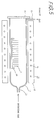
- the silicon substrate 1 is then treated using, for example, the horizontal heat treatment apparatus 10 shown in Fig. 5.
- the heat treatment apparatus 10 comprises a core tube 11, for example, made of quartz, and an electric furnace 12.
- a gas inlet tube 13 is connected to one end of the core tube 11, and the other end thereof is closed by a detachable cap 14 for discharging the substance treated.
- a gas exhaust tube 15 is also provided near the other end of the core tube 11.
- the electric furnace 12 is provided with, for example, a resistance heater 14. Atmospheric oxygen and nitrogen are supplied to the inside of the core tube 11 at flow rates of 6 sccm and 24 sccm, respectively, from the gas inlet tube 13.
- the current of the resistance heater 14 is controlled so that the temperature at the central portion of the core tube 11 is a predetermined temperature, e.g., 400°C.
- the gases introduced into the core tube 11 are spontaneously exhausted from the gas exhaust tube 15.
- the silicon substrate 1 held by a quartz carrier 16 is inserted into the core tube 11 and then heated for a predetermined time, for example 30 minutes.
- a predetermined time for example 30 minutes.
- the surface of the TiN film 5 is oxidized to form an oxide film 6 having a thickness of about 30 ⁇ , as shown in Fig. 2.
- An aluminum film 7 containing 2% copper and having a thickness of about 0.5 ⁇ m is then deposited on the silicon substrate 1 by a known sputtering process, as shown in Fig. 3.
- a BPSG cover film 8 is deposited on the silicon substrate 1, as shown in Fig. 4.
- the silicon substrate 1 is then annealed at 450°C for 30 minutes in a gas mixture, for example, containing nitrogen and hydrogen.
- the cover film 8 is generally deposited by the CVD process at a temperature of about 425°C.
- the subsequent heat treatment such as annealing or the like, interdiffusion between the aluminum film 7 and the silicon substrate 1 and reaction between the aluminum film 7 and the TiN film 5 are inhibited by the oxide film 6. It is thus possible to completely avoid the phenomenon that the PN junction between the impurity diffusion layer 2 and the silicon substrate 1 is destroyed by so-called aluminum spike. The reliability of connection between the wiring formed by the aluminum film 7 and the silicon substrate 1 can thus be guaranteed.
- the present method also prevents an increase in resistance or breakage of the aluminum wiring which is caused by electromigration and thus improves the MTF (mean time to failure) characteristics. A conceivable cause for this is that since the reaction between the aluminum film 7 and the TiN film 5 is inhibited during the heat treatment, the crystal grains in the aluminum film 7 is easily grown, and electromigration is thus inhibited.
- the present embodiment thus enables the thickness and properties of the oxide film 6 to be controlled with good reproducibility.
- the method also enables the cooling time required until the silicon substrate 1 is discharged to air, i.e., the time taken for cooling the temperature of the heat treatment apparatus from the oxidation temperature of 400°C to, for example, 300°C or less, to be decreased to about 20 minutes or less. Consequently, it is possible to avoid substantially decreasing the throughput of the treatment process.
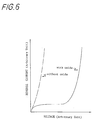
- Fig. 6 is a graph showing the reverse current-voltage characteristics of a PN junction which was connected to the aluminum wiring formed by the process shown in Figs. 1 to 4.
- the characteristics of the case where the TiN film 5 was not subjected to the above-described oxidation are shown by a broken line.
- the case where oxidation was effected in accordance with the present embodiment shows normal reverse characteristics of voltage resistance.
- the case without oxidation produces junction leak showing substantially ohmic current-voltage characteristics. This fact indicates that reaction between the aluminum film 7 and the silicon substrate 1 or the TiN film 5 cannot be inhibited by the natural oxide film which is estimated to be present on the surface of the TiN film 5.
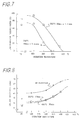
- Fig. 7 is a graph showing a relation between the oxidation temperature and the junction leak failure ratio when a TiN barrier layer was oxidized in an atmosphere containing 20% oxygen and 80% nitrogen.
- the parameter shows a difference in conditions of heat treatment performed after aluminum wiring was formed, i.e., a difference between the case where heat treatment at 500°C for 30 minutes was performed twice and the case where this heat treatment was performed three times.
- the junction leak failure ratio starts to decrease at an oxidation temperature of 300°C and reaches substantially zero at a temperature of 400°C, as compared with the case without oxidation. It is a matter of course that the failure ratio increases as conditions of after heat treatment become severer.
- the conditions of after heat treatment of course depend upon the type of the semiconductor device produced.
- Fig. 8 is a graph showing a relation between the oxidation temperature and the contact resistance of aluminum wiring when a TiN barrier layer was oxidized in an atmosphere containing 20%n oxygen and 80% nitrogen.
- the parameter shows a difference in conditions of heat treatment after the aluminum wiring was formed, i.e., a difference between the case where no heat treatment was performed after oxidation and the case where after heat treatment was performed in an atmosphere of nitrogen at 450°C and 500°C.
- the time of the after heat treatment is 30 minutes in all the cases.
- the contact resistance increases as the oxidation temperature increases. Although the contact resistance is increased by oxidation at 400°C by about 20%, as compared with that of the case without oxidation, such a increase in contact resistance is not critical to usual semiconductor devices.
- Such an increase in contact resistance shows that the formation of an oxide film on the surface of the TiN film is promoted as the oxidation temperature increases. It is thought from the phenomenon that the contact resistance is decreased by after heat treatment and the fact shown in Fig. 7 that the oxide film formed on the surface of the TiN film is reduced by the aluminum wiring when the conditions of after heat treatment become severer. However, the fact shown in Fig. 7 that the junction-leak failure ratio is low even if after-heat treatment is performed 2 to 3 times at 500°C for 30 minutes indicates that the oxide film still has the effect on the interdiffusion between the aluminum wiring and the silicon substrate after heat treatment.
- the temperature of oxidation for forming the oxide film 6 is selected from the range from 350°C to 450°C. Since oxidation at a temperature above 450°C further increases the contact resistance of the aluminum film 7 with the silicon substrate 1 and causes the aluminum wiring 7 to be easily deteriorated by electromigration, such a temperature is undesirable. An oxidation time of 15 to 60 minutes has great difference in effect within the above temperature range. However, an oxidation time of 60 minutes or more is undesirable because the contact resistance is further increased. In regard to the atmosphere of heat treatment, if the flow rate ratio is controlled so that the oxygen concentration is 20 ⁇ 5%, and the nitrogen concentration is 80 ⁇ 5%, there is no difference in effect. It is estimated that the oxide film formed on the surface of the TiN barrier layer by heat treatment under conditions within the above optimum ranges has a thickness of 20 to 50 ⁇ which allows conductivity to be maintained by the tunnel effect.
- the oxide film 6 is formed on the surface of the TiN film 5 by a method of immersing the TiN film 5 in an oxidizing chemical such as nitric acid or the like.
- an oxidizing chemical such as nitric acid or the like.
- the silicon substrate 1 having the TiN film 5 formed thereon, as shown in Fig. 1 is immersed in a concentrated nitric acid solution heated at, for example, 60°C for about 10 minutes, washed with water for 10 minutes and then dried in a constant temperature bath at 60°C for 10 minutes.
- the aluminum film 7 is then deposited and patterned to form wiring, and the cover film 8 is then deposited in the same way as that shown in Fig. 3.
- the TiN film 5 is interposed as a barrier layer between the silicon substrate 1 and the aluminum film 7, when a surface oxide film is formed by the same method as that employed in the above embodiment using a titanium-tungsten alloy or platinum or nickel silicide for forming a barrier layer in place of the TiN film 5, the same effects can be obtained.
Landscapes
- Internal Circuitry In Semiconductor Integrated Circuit Devices (AREA)
- Electrodes Of Semiconductors (AREA)
- Formation Of Insulating Films (AREA)
Applications Claiming Priority (2)
| Application Number | Priority Date | Filing Date | Title |
|---|---|---|---|
| JP20605/91 | 1991-02-14 | ||
| JP3020605A JPH04259242A (ja) | 1991-02-14 | 1991-02-14 | 半導体装置の製造方法 |
Publications (2)
| Publication Number | Publication Date |
|---|---|
| EP0499249A2 true EP0499249A2 (de) | 1992-08-19 |
| EP0499249A3 EP0499249A3 (en) | 1993-02-24 |
Family
ID=12031901
Family Applications (1)
| Application Number | Title | Priority Date | Filing Date |
|---|---|---|---|
| EP19920102410 Withdrawn EP0499249A3 (en) | 1991-02-14 | 1992-02-13 | Method of producing a semiconductor device including a barrier layer |
Country Status (4)
| Country | Link |
|---|---|
| US (1) | US5236869A (de) |
| EP (1) | EP0499249A3 (de) |
| JP (1) | JPH04259242A (de) |
| KR (1) | KR960005038B1 (de) |
Cited By (3)
| Publication number | Priority date | Publication date | Assignee | Title |
|---|---|---|---|---|
| GB2285337A (en) * | 1993-12-28 | 1995-07-05 | Fujitsu Ltd | Manufacture of semiconductor device with aluminium wiring |
| US6724088B1 (en) * | 1999-04-20 | 2004-04-20 | International Business Machines Corporation | Quantum conductive barrier for contact to shallow diffusion region |
| US9786762B2 (en) | 2012-08-29 | 2017-10-10 | Longitude Semiconductor S.A.R.L. | Gate electrode of a semiconductor device, and method for producing same |
Families Citing this family (18)
| Publication number | Priority date | Publication date | Assignee | Title |
|---|---|---|---|---|
| KR950009934B1 (ko) * | 1992-09-07 | 1995-09-01 | 삼성전자주식회사 | 반도체 장치의 배선층 형성방법 |
| US5378660A (en) * | 1993-02-12 | 1995-01-03 | Applied Materials, Inc. | Barrier layers and aluminum contacts |
| JP3201061B2 (ja) * | 1993-03-05 | 2001-08-20 | ソニー株式会社 | 配線構造の製造方法 |
| US5506449A (en) * | 1993-03-24 | 1996-04-09 | Kawasaki Steel Corporation | Interconnection structure for semiconductor integrated circuit and manufacture of the same |
| DE19515564B4 (de) | 1994-04-28 | 2008-07-03 | Denso Corp., Kariya | Elektrode für ein Halbleiterbauelement und Verfahren zur Herstellung derselben |
| US5514908A (en) * | 1994-04-29 | 1996-05-07 | Sgs-Thomson Microelectronics, Inc. | Integrated circuit with a titanium nitride contact barrier having oxygen stuffed grain boundaries |
| TW319891B (en) * | 1996-02-02 | 1997-11-11 | Taiwan Semiconductor Mfg | Method for improved aluminium-copper deposition and robust via contact resistance |
| US5693561A (en) * | 1996-05-14 | 1997-12-02 | Lucent Technologies Inc. | Method of integrated circuit fabrication including a step of depositing tungsten |
| US5913144A (en) * | 1996-09-20 | 1999-06-15 | Sharp Microelectronics Technology, Inc. | Oxidized diffusion barrier surface for the adherence of copper and method for same |
| US5918150A (en) * | 1996-10-11 | 1999-06-29 | Sharp Microelectronics Technology, Inc. | Method for a chemical vapor deposition of copper on an ion prepared conductive surface |
| JP3974284B2 (ja) * | 1999-03-18 | 2007-09-12 | 株式会社東芝 | 半導体装置の製造方法 |
| JP2001060590A (ja) | 1999-08-20 | 2001-03-06 | Denso Corp | 半導体装置の電気配線及びその製造方法 |
| US6433429B1 (en) * | 1999-09-01 | 2002-08-13 | International Business Machines Corporation | Copper conductive line with redundant liner and method of making |
| US6777327B2 (en) * | 2001-03-28 | 2004-08-17 | Sharp Laboratories Of America, Inc. | Method of barrier metal surface treatment prior to Cu deposition to improve adhesion and trench filling characteristics |
| JP3648480B2 (ja) * | 2001-12-26 | 2005-05-18 | 株式会社東芝 | 半導体装置およびその製造方法 |
| KR100919378B1 (ko) * | 2002-10-28 | 2009-09-25 | 매그나칩 반도체 유한회사 | 반도체 소자의 금속 배선 및 이의 형성 방법 |
| US20080000521A1 (en) * | 2006-05-15 | 2008-01-03 | Siva Sivoththaman | Low-temperature doping processes for silicon wafer devices |
| JP5057113B2 (ja) * | 2009-11-17 | 2012-10-24 | セイコーエプソン株式会社 | 半導体装置および電子部品並びにそれらの製造方法 |
Family Cites Families (8)
| Publication number | Priority date | Publication date | Assignee | Title |
|---|---|---|---|---|
| US4307132A (en) * | 1977-12-27 | 1981-12-22 | International Business Machines Corp. | Method for fabricating a contact on a semiconductor substrate by depositing an aluminum oxide diffusion barrier layer |
| US4200474A (en) * | 1978-11-20 | 1980-04-29 | Texas Instruments Incorporated | Method of depositing titanium dioxide (rutile) as a gate dielectric for MIS device fabrication |
| JPS5948647A (ja) * | 1982-09-13 | 1984-03-19 | Mitsubishi Electric Corp | 感湿材料の製造方法 |
| JPS61110449A (ja) * | 1984-11-05 | 1986-05-28 | Hitachi Ltd | 半導体装置の製造方法 |
| US4839010A (en) * | 1985-08-30 | 1989-06-13 | Texas Instruments Incorporated | Forming an antireflective coating for VLSI metallization |
| JPS62113421A (ja) * | 1985-11-13 | 1987-05-25 | Toshiba Corp | 半導体装置の製造方法 |
| NL9000602A (nl) * | 1990-03-16 | 1991-10-16 | Philips Nv | Werkwijze voor het vervaardigen van een halfgeleiderinrichting met geheugenelementen vormende condensatoren met een ferroelectrisch dielectricum. |
| US5175126A (en) * | 1990-12-27 | 1992-12-29 | Intel Corporation | Process of making titanium nitride barrier layer |
-
1991
- 1991-02-14 JP JP3020605A patent/JPH04259242A/ja active Pending
-
1992
- 1992-02-10 US US07/833,003 patent/US5236869A/en not_active Expired - Lifetime
- 1992-02-13 EP EP19920102410 patent/EP0499249A3/en not_active Withdrawn
- 1992-02-14 KR KR1019920002246A patent/KR960005038B1/ko not_active Expired - Fee Related
Cited By (4)
| Publication number | Priority date | Publication date | Assignee | Title |
|---|---|---|---|---|
| GB2285337A (en) * | 1993-12-28 | 1995-07-05 | Fujitsu Ltd | Manufacture of semiconductor device with aluminium wiring |
| GB2285337B (en) * | 1993-12-28 | 1997-12-17 | Fujitsu Ltd | Manufacture of semiconductor device with aluminium wiring |
| US6724088B1 (en) * | 1999-04-20 | 2004-04-20 | International Business Machines Corporation | Quantum conductive barrier for contact to shallow diffusion region |
| US9786762B2 (en) | 2012-08-29 | 2017-10-10 | Longitude Semiconductor S.A.R.L. | Gate electrode of a semiconductor device, and method for producing same |
Also Published As
| Publication number | Publication date |
|---|---|
| US5236869A (en) | 1993-08-17 |
| KR960005038B1 (ko) | 1996-04-18 |
| EP0499249A3 (en) | 1993-02-24 |
| JPH04259242A (ja) | 1992-09-14 |
| KR920017184A (ko) | 1992-09-26 |
Similar Documents
| Publication | Publication Date | Title |
|---|---|---|
| US5236869A (en) | Method of producing semiconductor device | |
| US4902645A (en) | Method of selectively forming a silicon-containing metal layer | |
| US4988423A (en) | Method for fabricating interconnection structure | |
| CA1306072C (en) | Refractory metal - titanium nitride conductive structures and processes for forming the same | |
| KR960010056B1 (ko) | 반도체장치 및 그 제조 방법 | |
| US6174810B1 (en) | Copper interconnect structure and method of formation | |
| JP3584054B2 (ja) | 半導体装置及びその製造方法 | |
| KR0140379B1 (ko) | 도전 구조체를 반도체 소자내에 선택적으로 인캡슐레이션하기 위한 방법 | |
| US6255733B1 (en) | Metal-alloy interconnections for integrated circuits | |
| US5736455A (en) | Method for passivating the sidewalls of a tungsten word line | |
| US5449640A (en) | Fabricating electrical contacts in semiconductor devices | |
| KR100281887B1 (ko) | 반도체장치의 제조방법 | |
| US5278448A (en) | Semiconductor device and method of fabricating the same | |
| US5430258A (en) | Copper interconnection structure and method of preparing same | |
| US5494860A (en) | Two step annealing process for decreasing contact resistance | |
| JPH024971A (ja) | 半導体装置の製造方法 | |
| EP0460874A2 (de) | Verfahren zur Herstellung elektrischer Kontakte für integrierte Schaltungen mit flachen Uebergängen | |
| KR100238564B1 (ko) | 반도체 소자 제조 방법 | |
| JPH06181212A (ja) | 半導体装置の製造方法 | |
| JPH09186103A (ja) | 金属配線の構造及びその形成方法 | |
| JPH06204170A (ja) | 半導体装置およびその製造方法 | |
| KR20030050652A (ko) | 텅스텐막의 형성 방법 | |
| JPH02314A (ja) | シリコン含有金属膜の形成方法 | |
| US5908321A (en) | Semiconductor structure with stable pre-reacted particle and method for making | |
| JPH04350937A (ja) | 銅配線の処理方法 |
Legal Events
| Date | Code | Title | Description |
|---|---|---|---|
| PUAI | Public reference made under article 153(3) epc to a published international application that has entered the european phase |
Free format text: ORIGINAL CODE: 0009012 |
|
| AK | Designated contracting states |
Kind code of ref document: A2 Designated state(s): DE FR GB |
|
| PUAL | Search report despatched |
Free format text: ORIGINAL CODE: 0009013 |
|
| AK | Designated contracting states |
Kind code of ref document: A3 Designated state(s): DE FR GB |
|
| 17P | Request for examination filed |
Effective date: 19930510 |
|
| 17Q | First examination report despatched |
Effective date: 19950418 |
|
| STAA | Information on the status of an ep patent application or granted ep patent |
Free format text: STATUS: THE APPLICATION IS DEEMED TO BE WITHDRAWN |
|
| 18D | Application deemed to be withdrawn |
Effective date: 19960730 |