EP0498210A1 - Steuerungsvorrichtung für ein stufenlos regelbares Getriebe - Google Patents
Steuerungsvorrichtung für ein stufenlos regelbares Getriebe Download PDFInfo
- Publication number
- EP0498210A1 EP0498210A1 EP92100947A EP92100947A EP0498210A1 EP 0498210 A1 EP0498210 A1 EP 0498210A1 EP 92100947 A EP92100947 A EP 92100947A EP 92100947 A EP92100947 A EP 92100947A EP 0498210 A1 EP0498210 A1 EP 0498210A1
- Authority
- EP
- European Patent Office
- Prior art keywords
- valve
- solenoid
- hydraulic pressure
- controlling
- operated
- Prior art date
- Legal status (The legal status is an assumption and is not a legal conclusion. Google has not performed a legal analysis and makes no representation as to the accuracy of the status listed.)
- Granted
Links
Images


Classifications
-
- F—MECHANICAL ENGINEERING; LIGHTING; HEATING; WEAPONS; BLASTING
- F16—ENGINEERING ELEMENTS AND UNITS; GENERAL MEASURES FOR PRODUCING AND MAINTAINING EFFECTIVE FUNCTIONING OF MACHINES OR INSTALLATIONS; THERMAL INSULATION IN GENERAL
- F16H—GEARING
- F16H61/00—Control functions within control units of change-speed- or reversing-gearings for conveying rotary motion ; Control of exclusively fluid gearing, friction gearing, gearings with endless flexible members or other particular types of gearing
- F16H61/66—Control functions within control units of change-speed- or reversing-gearings for conveying rotary motion ; Control of exclusively fluid gearing, friction gearing, gearings with endless flexible members or other particular types of gearing specially adapted for continuously variable gearings
- F16H61/662—Control functions within control units of change-speed- or reversing-gearings for conveying rotary motion ; Control of exclusively fluid gearing, friction gearing, gearings with endless flexible members or other particular types of gearing specially adapted for continuously variable gearings with endless flexible members
- F16H61/66254—Control functions within control units of change-speed- or reversing-gearings for conveying rotary motion ; Control of exclusively fluid gearing, friction gearing, gearings with endless flexible members or other particular types of gearing specially adapted for continuously variable gearings with endless flexible members controlling of shifting being influenced by a signal derived from the engine and the main coupling
- F16H61/66259—Control functions within control units of change-speed- or reversing-gearings for conveying rotary motion ; Control of exclusively fluid gearing, friction gearing, gearings with endless flexible members or other particular types of gearing specially adapted for continuously variable gearings with endless flexible members controlling of shifting being influenced by a signal derived from the engine and the main coupling using electrical or electronical sensing or control means
-
- F—MECHANICAL ENGINEERING; LIGHTING; HEATING; WEAPONS; BLASTING
- F16—ENGINEERING ELEMENTS AND UNITS; GENERAL MEASURES FOR PRODUCING AND MAINTAINING EFFECTIVE FUNCTIONING OF MACHINES OR INSTALLATIONS; THERMAL INSULATION IN GENERAL
- F16H—GEARING
- F16H61/00—Control functions within control units of change-speed- or reversing-gearings for conveying rotary motion ; Control of exclusively fluid gearing, friction gearing, gearings with endless flexible members or other particular types of gearing
- F16H61/12—Detecting malfunction or potential malfunction, e.g. fail safe; Circumventing or fixing failures
- F16H2061/122—Avoiding failures by using redundant parts
-
- F—MECHANICAL ENGINEERING; LIGHTING; HEATING; WEAPONS; BLASTING
- F16—ENGINEERING ELEMENTS AND UNITS; GENERAL MEASURES FOR PRODUCING AND MAINTAINING EFFECTIVE FUNCTIONING OF MACHINES OR INSTALLATIONS; THERMAL INSULATION IN GENERAL
- F16H—GEARING
- F16H61/00—Control functions within control units of change-speed- or reversing-gearings for conveying rotary motion ; Control of exclusively fluid gearing, friction gearing, gearings with endless flexible members or other particular types of gearing
- F16H61/12—Detecting malfunction or potential malfunction, e.g. fail safe; Circumventing or fixing failures
- F16H2061/1256—Detecting malfunction or potential malfunction, e.g. fail safe; Circumventing or fixing failures characterised by the parts or units where malfunctioning was assumed or detected
- F16H2061/126—Detecting malfunction or potential malfunction, e.g. fail safe; Circumventing or fixing failures characterised by the parts or units where malfunctioning was assumed or detected the failing part is the controller
- F16H2061/1268—Electric parts of the controller, e.g. a defect solenoid, wiring or microprocessor
-
- F—MECHANICAL ENGINEERING; LIGHTING; HEATING; WEAPONS; BLASTING
- F16—ENGINEERING ELEMENTS AND UNITS; GENERAL MEASURES FOR PRODUCING AND MAINTAINING EFFECTIVE FUNCTIONING OF MACHINES OR INSTALLATIONS; THERMAL INSULATION IN GENERAL
- F16H—GEARING
- F16H61/00—Control functions within control units of change-speed- or reversing-gearings for conveying rotary motion ; Control of exclusively fluid gearing, friction gearing, gearings with endless flexible members or other particular types of gearing
- F16H61/12—Detecting malfunction or potential malfunction, e.g. fail safe; Circumventing or fixing failures
- F16H2061/1256—Detecting malfunction or potential malfunction, e.g. fail safe; Circumventing or fixing failures characterised by the parts or units where malfunctioning was assumed or detected
- F16H2061/1292—Detecting malfunction or potential malfunction, e.g. fail safe; Circumventing or fixing failures characterised by the parts or units where malfunctioning was assumed or detected the failing part is the power supply, e.g. the electric power supply
Definitions
- the present invention relates to a control system for controlling the engagement of a clutch and the speed ratio of a continuously variable transmission, and more particularly to a control system for electrically controlling the engagement of a clutch and the speed ratio of a continuously variable transmission.
- Continuously variable transmissions such as belt-type continuously variable transmissions have been proposed in the past, and have already found use in automobiles or the like.
- the belt-type continuously variable transmissions typically comprise a metallic V-belt trained around drive and driven movable pulleys whose width is variable.
- the belt-type continuously variable transmissions are often required to have a neutral state, which is achieved by a clutch that is disposed in the power transmission path from an input shaft to an output shaft for selectively transmitting engine power from the input shaft to the output shaft.
- the speed ratio of the belt-type continuously variable transmission is controlled when the widths of the drive and driven pulleys vary.
- the clutch is controlled to select the neutral state and also to start moving the automobile.
- the belt-type continuously variable transmission has a hydraulic cylinder for imparting a lateral pressure to the movable pulley cone of each of the pulleys.
- the lateral pressure applied to the movable pulley member by the hydraulic cylinder is controlled to vary the effective pulley diameters for thereby controlling the speed ratio.
- the control of the lateral pressure applied to the pulleys is also effective to control the tension of the V-belt.
- One known control system for controlling a belt-type continuously variable transmission is disclosed in Japanese Laid-Open Patent Publication No. 61-206862, for example.
- Japanese Laid-Open Patent Publication No. 63-215437 discloses a control system for controlling a belt-type continuously variable transmission with controlling hydraulic pressures generated on the basis of electric signals.
- the controlling hydraulic pressures are generated using solenoid-operated valves and an electrically operated actuator based on the electric signals.
- the solenoid-operated valves and the electrically operated actuators fail to operate, and the belt-type continuously variable transmission cannot be controlled.
- Another object of the present invention is to provide a control system which is capable of controlling a continuously variable transmission to some extent even in the event of an electric failure that cuts off the supply of electric energy to solenoid-operated valves and an electrically operated actuator which generate controlling hydraulic pressures.
- Still another object of the present invention is to provide a control system which enables a continuously variable transmission incorporated in a motor vehicle to control the running of the motor vehicle even in the event of an electric failure that cuts off the supply of electric energy to solenoid-operated valves and an electrically operated actuator which generate controlling hydraulic pressures.
- a control system for a continuously variable transmission having a hydraulic actuator for effecting at least one of speed ratio control and clutch control comprising a solenoid-operated control valve for generating a controlling hydraulic pressure to be supplied to the hydraulic actuator, hydraulic pressure generating means for generating a hydraulic pressure corresponding to the rotational speed of an engine which is associated with the continuously variable transmission, a directional control valve for selectively connecting the solenoid-operated control valve and the hydraulic pressure generating means to the hydraulic actuator, and a solenoid-operated on-off valve for controlling the directional control valve such that when a solenoid of the solenoid-operated on-off valve is energized, the directional control valve connects the solenoid-operated control valve means to the hydraulic actuator, and when the solenoid of the solenoid-operated on-off valve is de-energized, the directional control valve connects the hydraulic pressure generating means to the hydraulic actuator.
- a control system for a continuously variable transmission having a starting clutch actuator for actuating a starting clutch disposed in a power transmission path from an input shaft to an output shaft, for selectively transmitting power along the power transmission path
- the control system comprising a solenoid-operated control valve for generating a controlling hydraulic pressure to be supplied to the starting clutch actuator in response to a controlling current, hydraulic pressure generating means for generating a hydraulic pressure corresponding to the rotational speed of an engine which rotates the input shaft, a directional control valve for selectively connecting the solenoid-operated control valve and the hydraulic pressure generating means to the starting clutch actuator, and a solenoid-operated on-off valve for controlling the directional control valve such that when a solenoid of the solenoid-operated on-off valve is energized, the directional control valve connects the solenoid-operated control valve to the starting clutch actuator, and when the solenoid of the solenoid-operated on-off valve is de-energized, the
- a control system for a belt-type continuously variable transmission having an input shaft, a drive movable pulley coupled to the input shaft, an output shaft, a driven movable pulley coupled to the output shaft, a V-belt trained around the drive and driven movable pulleys, a drive pulley cylinder for varying a width of the drive movable pulley, and a driven pulley cylinder for varying a width of the driven movable pulley
- the control system comprising a regulator valve assembly for generating a pulley controlling hydraulic pressure to be supplied to at least one of the drive and driven pulley cylinders for controlling the pulley thereof, an electrically operated actuator, a shift valve actuatable by the electrically operated actuator for supplying the pulley controlling hydraulic pressure from the regulator valve assembly to the drive and driven pulley cylinders, hydraulic pressure generating means for generating a hydraulic pressure corresponding to the rotational speed of an engine which rotates the input shaft,
- FIG. 1 schematically shows the power transmission path of a V-belt-type continuously variable transmission controllable by a control system according to the present invention.
- the V-belt-type continuously variable transmission generally comprises a metallic V-belt mechanism 10 disposed between and operatively coupled to an input shaft 1 and a countershaft 2, a planetary-gear forward/reverse selector mechanism 20 disposed between and operatively coupled to the input shaft 1 and a drive movable pulley 11, and a starting clutch 5 disposed between and operatively coupled to the countershaft 2 and output shafts 3a, 3b.
- the V-belt-type continuously variable transmission is incorporated in a motor vehicle with the input shaft 1 connected to the engine output shaft and the output shafts 3a, 3b to respective road wheels.
- the metallic V-belt mechanism 10 comprises a drive movable pulley 11 mounted on the input shaft 1, a driven movable pulley 16 disposed on the countershaft 2, and a metallic V-belt 15 trained around the pulleys 11, 16.
- the drive movable pulley 11 comprises a fixed pulley cone 12 rotatably mounted on the input shaft 1, and a movable pulley cone 13 axially movable toward and away from the fixed pulley cone 12.
- a cylinder chamber 14 is defined laterally of the movable pulley cone 13 by a cylinder wall 12a joined to the fixed pulley cone 12.
- the cylinder chamber 14 is supplied with a hydraulic pressure to develop a lateral pressure that acts to move the movable pulley cone 13 axially.
- the driven movable pulley 16 comprises a fixed pulley cone 17 fixedly mounted on the countershaft 2, and a movable pulley cone 18 axially movable toward and away from the fixed pulley cone 17.
- a cylinder chamber 19 is defined laterally of the movable pulley cone 18 by a cylinder wall 17a joined to the fixed pulley cone 17.
- the cylinder chamber 19 is supplied with a hydraulic pressure to develop a lateral pressure that acts to move the movable pulley cone 18 axially.
- the widths of the pulleys 11, 16 vary to change the effective pulley diameters for continuously varying the speed ratio that is established by the metallic V-belt mechanism 10.
- the planetary-gear forward/reverse selector mechanism 20 comprises a sun gear 21 coupled to the input shaft 1, a carrier 22 coupled to the fixed pulley cone 12, a ring gear 23 that can be held against rotation by a reverse brake 27, a plurality of planet gears rotatably supported on the carrier 22 and held in mesh with the sun gear 21 and the ring gear 23, and a forward clutch 25 for selectively connecting the sun gear 21 and the ring gear 23 to each other.
- the forward clutch 25 When the forward clutch 25 is engaged, the gears 21, 22, 23 rotate in unison with the input shaft 1, rotating the drive pulley 11 in the same direction (forward direction) as the input shaft 11.
- the reverse brake 27 is engaged, the ring gear 23 is held against rotation, and hence the carrier 22 rotates in the direction opposite to the direction in which the sun gear 21 rotates, rotating the drive pulley 11 in the opposite direction (reverse direction) to the input shaft 1.
- the starting clutch 5 serves to selectively transmit the engine power between the countershaft 2 and the output shafts 3a, 3b.
- the starting clutch 5 When the starting clutch 5 is engaged by a biassing force produced by a hydraulic actuator (hydraulic cylinder) 5a, it transmits the engine power from the countershaft 2 to the output shafts 3a, 3b. More specifically, when the starting clutch 5 is engaged, the engine power transmitted, with an adjusted speed ratio, from the metallic V-belt mechanism 10 is transmitted through gears 6a, 6b to a differential 4, from which the engine power is transmitted to the output shafts 3a, 3b and the road wheels. When the starting clutch 5 is disengaged, the engine power is not transmitted from the countershaft 2 to the output shafts 3a, 3b. At this time, the V-belt-type continuously variable transmission is in a neutral state.
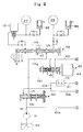
- FIGS. 2 and 3 jointly illustrate a single hydraulic circuit of the control system that includes hydraulic passages 1 , 2 , 3 , 4 interconnected between FIGS. 2 and 3.
- the hydraulic circuit includes a tank 30 from which working oil is supplied to a hydraulic passage 101 by a hydraulic pump 31.
- the working oil is then supplied through a hydraulic passage 101a to a clutch reducing valve 40.
- the working oil is reduced in pressure by the clutch reducing valve 40, and then supplied under a line pressure P1 to a hydraulic passage 110.
- the working oil discharged from the hydraulic pump 31 to the hydraulic passage 101 is also supplied to a high-pressure regulator valve 55 through a hydraulic passage 101b.
- the controlling hydraulic pressure supplied to the cylinder chambers 14, 19 of the metallic V-belt mechanism 10 for imparting a lateral pressure to the pulleys 11, 16, is generated by a high-/low-pressure control valve 50, the high-pressure regulator valve 55, and a low-pressure regulator valve 57.
- the high-/low-pressure control valve 50 is supplied with the line pressure P1 from the clutch reducing valve 40 through hydraulic passages 110b, 110c.
- the high-/low-pressure control valve 50 converts the line pressure P1 into a controlling back pressure P2 corresponding to a pushing force applied to a spool 52 by a linear solenoid 51, and supplies the controlling back pressure P2 to a hydraulic passage 120.
- the high-/low-pressure control valve 50 is arranged such that when the pushing force applied to the spool 52 by the linear solenoid 51 is minimum, the controlling back pressure P2 is maximum and equal to the line pressure P1. In the event of an electric failure that de-energizes the linear solenoid 51, the controlling back pressure P2 is equalized to the line pressure P1.
- the controlling back pressure P2 is supplied to the high-pressure regulator valve 55 and the low-pressure regulator valve 57 through respective hydraulic passages 120a, 120b.
- the high-pressure regulator valve 55 converts the hydraulic pressure supplied from the pump 31 through the hydraulic passage 101b into a high controlling pressure PH corresponding to a pushing force applied to a spool 56 thereof under the controlling back pressure P2.
- the high-pressure regulator valve 55 supplies the high controlling pressure PH to a hydraulic passage 102.
- the low-pressure regulator valve 57 converts the high controlling pressure PH supplied thereto through the hydraulic passage 102 and a hydraulic passage 102a into a low controlling pressure PL corresponding to a pushing force applied to a spool 58 thereof under the controlling back pressure P2.
- the low-pressure regulator valve 57 supplies the low controlling pressure PL to a hydraulic passage 103.
- the high controlling pressure PH and the low controlling pressure PL are supplied through a shift valve 60 to the cylinder chambers 14, 19 of the V-belt mechanism 10 for controlling the speed ratio.
- the linear solenoid 51 of the high-/low-pressure control valve 50 generates the pushing force depending on the throttle opening of the engine, and the speed ratio of the V-belt mechanism 10, so that the high controlling pressure PH and the low controlling pressure PL are maintained in a predetermined relationship to the throttle opening and the speed ratio.
- the hydraulic passage 120a has an orifice 53 for making the low-pressure regulator valve 57 more responsive to the controlling back pressure P2 than the high-pressure regulator valve 55.
- the high-pressure regulator valve 55 serves as a valve for regulating the pressure of the working oil discharged by the pump 31.
- the low controlling pressure PL developed by the low-pressure regulator valve 57 serves to control the tension of the V-belt 15, and hence is set to a level for keeping the V-belt 15 under desired tension.
- the high controlling pressure PH and the low controlling pressure PL thus developed are supplied respectively to the cylinder chambers 14, 19 of the pulleys 11, 16 for varying the pulley widths thereby to control the speed ratio.
- the shift valve 60, a shift inhibitor valve 65, and a ratio inhibitor valve 67 are provided to control the selective supply of the high controlling pressure PH and the low controlling pressure PL to the cylinder chambers 14, 19.
- the shift valve 60 has a spool 61 that is normally urged to the right, as viewed in FIG. 3, by a spring 63.
- the spool 61 has a righthand end held against a cam 62a coupled to an electrically operated actuator 62. Therefore, the spool 61 can be positioned when the cam 62a is angularly moved by the electrically operated actuator 62.
- the shift valve 60 is supplied with the high controlling pressure PH through the hydraulic passage 102 and hydraulic passages 102b, 102c, and also with the low controlling pressure PL through the hydraulic passage 103 and hydraulic passages 103a, 103b.
- the high controlling pressure PH and the low controlling pressure PL are selectively supplied respectively to hydraulic passages 104a, 105a depending on the axial position of the spool 61.
- the axial position of the spool 61 is detected by a position sensor 64 that is held against the lefthand end of the spool 61.
- the ratio inhibitor valve 67 has a spool 68 that is normally urged to the left, as viewed in FIG. 3, by a spring 69.
- the working oil supplied to the hydraulic passages 104a, 105a flows through the ratio inhibitor valve 67 and hydraulic passages 104b, 105b into the cylinder chambers 14, 19.
- the electrically operated actuator 62 When the electrically operated actuator 62 is thus controlled in operation to shift the spool 61, the supply of the hydraulic pressures to the cylinder chambers 14, 19 is controlled for controlling the speed ratio.
- the operation of the electrically operated actuator 62 is controlled based on the throttle opening and rotational speed of the engine.
- the spool 68 of the ratio inhibitor valve 67 is normally urged to the left by the spring 69.
- a hydraulic passage 110e connected to the lefthand end of the ratio inhibitor valve 67 is supplied with the line pressure P1 through the hydraulic passages 110, 110b, a hydraulic passage 110d, and a solenoid-operated on-off valve 74, the spool 68 is axially shifted to the right under the line pressure P1.
- the spool 68 When the spool 68 is shifted to the right, it closes off the hydraulic passages 104a, 105a, and brings the hydraulic passages 104b, 104b into communication with hydraulic passages 103e, 103f, respectively.
- the solenoid-operated on-off valve 74 is a normally closed valve with its drain port being normally closed, and has a normally energized solenoid 74a. Therefore, when the solenoid 74a is energized, the solenoid-operated on-off valve 74 is closed, with no hydraulic pressure developed in the hydraulic passage 110e. When the solenoid 74a is de-energized, the solenoid-operated on-off valve 74 is opened to supply the line pressure P1 to the hydraulic passage 110e.
- the hydraulic passage 103e is connected to the shift inhibitor valve 65, so that the hydraulic pressure developed by the shift inhibitor valve 65 can be supplied to the cylinder chamber 14.
- the hydraulic passage 103f is connected to the low-pressure regulator valve 57, so that the cylinder chamber 19 can be supplied with the low controlling pressure PL. In the event of an electric failure, the linear solenoid 51 of the high-/low-pressure control valve 50 is not energized.
- the hydraulic passages 102, 103 are supplied with the high controlling pressure PH and the low controlling pressure PL corresponding to the controlling back pressure P2 from the high- and low-pressure regulator valves 55, 57.
- the shift inhibitor valve 65 is connected to a governor valve 70 through hydraulic passages 111a, 111.
- the governor valve 70 operates in synchronism with the rotation of the engine, and converts the line pressure P1 from the hydraulic passage 110 and a hydraulic passage 110a into a governor pressure PG corresponding to the rotational speed of the engine under centrifugal forces developed by the rotation of the engine.
- the governor pressure PG acts on the lefthand side of a spool 66 of the shift inhibitor valve 65, thereby shifting the spool 66 to the right as viewed in FIG. 3.
- the governor pressure PG is a hydraulic pressure that is commensurate with the rotational speed of the engine. While the hydraulic pressure commensurate with the rotational speed of the engine is generated by the governor valve 70 in the embodiment of FIGS. 2 and 3, the hydraulic pressure commensurate with the rotational speed of the engine may be a hydraulic pressure generated by a pitot tube 170 placed in a flow of working oil whose rate corresponds to the rotational speed of the engine as shown in FIG. 4. Alternatively, the hydraulic pressure commensurate with the rotational speed of the engine may be produced by an electro-hydraulic converter valve 270 that converts an electric signal indicative of the rotational speed of the engine from a speed sensor 271 into a corresponding hydraulic pressure as shown in FIG. 5.
- the spool 66 When the rotational speed of the engine is relatively low and hence the governor pressure PG is relatively low, the spool 66 is shifted to the left, allowing the low controlling pressure PL supplied from the low-pressure regulator valve 57 through the hydraulic passage 103 and hydraulic passages 103c, 103d to flow through the hydraulic passage 103e to the cylinder chamber 14 of the drive pulley 11.
- the spool 66 When the rotational speed of the engine is increased and hence the governor pressure PG is also increased, the spool 66 is shifted to the right under the governor pressure PG, allowing the high controlling pressure PH supplied from the high-pressure regulator valve 55 through the hydraulic passages 102, 102b and a hydraulic passage 102d to flow through the hydraulic passage 103e to the cylinder chamber 14 of the drive pulley 11.
- the cylinder 14 of the drive pulley 11 is supplied with the low controlling pressure PL when the rotational speed of the engine is comparatively low, and with the high controlling pressure PH when the rotational speed of the engine is comparatively high.
- the cylinder chamber 19 of the driven pulley 16 is supplied with the low controlling pressure PL.
- both of the cylinder chambers 14, 19 are supplied with the low controlling pressure PL.
- the widths of the drive and driven pulleys 11, 16 are equal to each other, and the speed ratio approaches 1.0. Since the V-belt 15 tends to bite into the drive pulley 11 due to the drive torque thereof, thereby reducing the effective pulley diameter, the speed ratio actually varies so that it is greater than 1.0 (i.e., varies toward the LOW position). This tendency is greater as the drive torque is larger. As the drive torque becomes larger, the speed ratio varies toward the LOW position. When the motor vehicle is subjected to engine brake, since the driven pulley 16 drives the drive pulley 11, the speed ratio varies so that it is smaller than 1.0 (i.e., varies toward the TOP position).
- the speed ratio is reduced to a minimum value (i.e., varies toward the TOP position).
- the ratio inhibitor valve 67 serves as a directional control valve.
- the controlling pressures PH, PL generated by the high- and low-pressure regulator valves 55, 57 are selectively supplied respectively to the cylinder chambers 14, 19 by the shift valve 60 for controlling the speed ratio.
- the control system according to the present invention is not limited to such an arrangement, but may be modified in various ways.
- the cylinder chamber 19 may always be supplied with a hydraulic pressure suitable for controlling the tension of the V-belt 15, and the cylinder chamber 14 may be supplied with a controlling pressure for controlling the speed ratio.
- the directional control valve ratio inhibitor valve
- the line pressure P1 is also supplied to a manual valve 46 through a hydraulic passage 110g for the control of the forward clutch 25 and the reverse brake 27.
- the manual valve 46 is connected to a shift lever (not shown) at the driver's seat through a control cable (not shown), so that the manual valve 46 can be operated manually by the driver of the motor vehicle.
- the shift lever can manually be moved selectively into six positions P, R, N, D, S, L (see FIG. 2).
- the manual valve 46 has a spool 47 that is moved into one of illustrated positions corresponding to the respective positions P, R, N, D, S, L, depending on the position into which the shift lever is manually shifted. In FIG. 2, the spool 47 is shown as being in the neutral position N.
- the manual valve 46 is connected to the forward clutch 25 through a hydraulic passage 115, and also to the reverse brake 27 through a hydraulic passage 116 having a solenoid-operated valve 72.
- the solenoid-operated valve 72 serves as a vehicle speed inhibitor that is actuated if the vehicle speed is higher than a predetermined speed when the shift lever is shifted into the position R while the motor vehicle is running. The vehicle speed inhibitor prevents the reverse brake 27 from being applied unless the vehicle speed drops below the predetermined speed.
- the starting clutch 5 is connected to a clutch control valve 43 through hydraulic passages 112, 113 and the ratio inhibitor valve 67 coupled between the hydraulic passages 112, 113, and is controlled for its engagement by a clutch controlling pressure PC supplied by the clutch control valve 43.
- the clutch control valve 43 has a linear solenoid 44 that controls a spool 45 to convert the line pressure PL supplied from a hydraulic passage 110f connected to the hydraulic passage 110 into the clutch controlling pressure PC.
- the solenoid-operated valve 43 When an electric failure causes an electric energy interruption, the solenoid-operated valve 43 is not actuated. At this time, since the spool 68 of the ratio inhibitor valve 67 is moved to the right, it closes the hydraulic passage 112, and connects the hydraulic passage 111 to the starting clutch 5 through a hydraulic passage 111b and the hydraulic passage 113. As the hydraulic passage 111 is connected to the governor valve 70, the starting clutch 5 is supplied with the governor pressure PG. Therefore, when the rotational speed of the engine is relatively low, the starting clutch 5 is disengaged, and when the rotational speed of the engine is relatively high, the starting clutch 5 is engaged.
- the starting clutch 5 is thus usually controlled by the clutch controlling pressure PC from the clutch control valve 43 that is electrically operated. In the event of an electric failure, the starting clutch 5 is controlled by the governor pressure PG from the governor valve 70. In this case, the ratio inhibitor valve 67 also serves as a directional control valve.
- the solenoid-operated clutch control valve when the solenoid-operated on-off valve is energized, the solenoid-operated clutch control valve is connected to the starting clutch by the directional control valve (ratio inhibitor valve), and when the solenoid-operated on-off valve is de-energized, the governor valve is connected to the starting clutch by the directional control valve. Therefore, in the event of an electric failure that interrupts the supply of controlling electric energy, the solenoid-operated on-off valve is de-energized, allowing the governor valve to be connected to the starting clutch. Thus, the starting clutch is controlled for its engagement under the governor pressure from the governor valve.
- the shift valve when the solenoid-operated on-off valve is energized, the shift valve is connected to the cylinder chambers of the drive and driven pulleys by the directional control valve (ratio inhibitor valve), and when the solenoid-operated on-off valve is de-energized, the shift inhibitor valve is connected to the cylinder chambers of the drive and driven pulleys by the directional control valve. Therefore, in the event of an electric failure that interrupts the supply of controlling electric energy, the solenoid-operated on-off valve is de-energized, allowing the shift inhibitor valve to be connected to at least one of the cylinder chambers of the drive and driven pulleys.
- the shift inhibitor valve is now actuated under the governor valve to supply hydraulic pressures to the cylinder chambers of the drive and driven pulleys through hydraulic passages other than the shift valve. Consequently, the speed ratio can be controlled to some extent, so that the running of the motor vehicle may be controlled even in the event of an electric failure.
- the belt-type continuously variable transmission can be controlled to vary the speed ratio.
- a belt-type continuously variable transmission for use with a motor vehicle engine has a hydraulic actuator for effecting at least one of speed ratio control and clutch control.
- the belt-type continuously variable transmission is controlled by a control system including a solenoid-operated control valve for generating a controlling hydraulic pressure to be supplied to the hydraulic actuator, a hydraulic pressure generator for generating a hydraulic pressure corresponding to the rotational speed of the engine, a directional control valve for selectively connecting the solenoid-operated control valve and the hydraulic pressure generating means to the hydraulic actuator, and a solenoid-operated on-off valve for controlling the directional control valve.
- the directional control valve When the solenoid of the solenoid-operated on-off valve is energized, the directional control valve connects the solenoid-operated control valve to the hydraulic actuator, and when the solenoid is de-energized, the directional control valve connects the hydraulic pressure generator to the hydraulic actuator.
Applications Claiming Priority (2)
| Application Number | Priority Date | Filing Date | Title |
|---|---|---|---|
| JP3021692A JP2937268B2 (ja) | 1991-01-22 | 1991-01-22 | ベルト式無段変速機の制御装置 |
| JP21692/91 | 1991-01-22 |
Publications (2)
| Publication Number | Publication Date |
|---|---|
| EP0498210A1 true EP0498210A1 (de) | 1992-08-12 |
| EP0498210B1 EP0498210B1 (de) | 1995-06-28 |
Family
ID=12062125
Family Applications (1)
| Application Number | Title | Priority Date | Filing Date |
|---|---|---|---|
| EP92100947A Expired - Lifetime EP0498210B1 (de) | 1991-01-22 | 1992-01-21 | Steuerungsvorrichtung für ein stufenlos regelbares Getriebe |
Country Status (4)
| Country | Link |
|---|---|
| US (1) | US5183439A (de) |
| EP (1) | EP0498210B1 (de) |
| JP (1) | JP2937268B2 (de) |
| DE (1) | DE69203103T2 (de) |
Cited By (15)
| Publication number | Priority date | Publication date | Assignee | Title |
|---|---|---|---|---|
| DE4234103A1 (de) * | 1991-10-11 | 1993-04-15 | Fuji Heavy Ind Ltd | Steuersystem fuer ein kontinuierlich veraenderliches getriebe |
| EP0615082A1 (de) * | 1993-03-08 | 1994-09-14 | Ford Motor Company Limited | Stufenloses Getriebe |
| EP0621421A1 (de) * | 1993-04-21 | 1994-10-26 | Honda Giken Kogyo Kabushiki Kaisha | Steuergerät für ein stufenloses Riemengetriebe |
| WO1996002768A1 (de) * | 1994-07-14 | 1996-02-01 | Robert Bosch Gmbh | Hydrauliknotsteuerung für eine zwischen einem verbrennungsmotor und einem getriebe angeordnete reibkupplung |
| WO1996012126A1 (de) * | 1994-10-13 | 1996-04-25 | Zf Friedrichshafen Ag | Einrichtung zum steuern eines cvt |
| EP0731296A1 (de) * | 1995-03-02 | 1996-09-11 | Honda Giken Kogyo Kabushiki Kaisha | Steuerung für ein stufenlos verstellbares Riemengetriebe |
| EP0727598A3 (de) * | 1995-01-26 | 1996-10-16 | Honda Motor Co Ltd | Steuergerät für Getriebe |
| BE1009148A3 (nl) * | 1995-02-21 | 1996-12-03 | Vcst Nv | Werkwijze voor het regelen van een transmissie-eenheid voor motorvoertuigen bij noodloop en transmissie-eenheid die volgens deze werkwijze wordt geregeld. |
| DE19534391A1 (de) * | 1995-09-16 | 1997-03-20 | Fichtel & Sachs Ag | Steueranordnung für ein Reibradgetriebe |
| DE19856297A1 (de) * | 1998-12-07 | 2000-06-15 | Bosch Gmbh Robert | Hydrauliknotsteuerung für eine zwischen einem Verbrennungsmotor und einem Getriebe angeordnete Kupplung |
| DE19920378A1 (de) * | 1999-05-04 | 2000-11-30 | Zahnradfabrik Friedrichshafen | Automatisch gesteuertes Getriebe |
| DE19943939A1 (de) * | 1999-09-14 | 2001-03-15 | Volkswagen Ag | Notsteuerung für ein Kraftfahrzeug |
| EP0982512A3 (de) * | 1998-08-26 | 2002-07-10 | Honda Giken Kogyo Kabushiki Kaisha | Hydraulische Kupplungssteuerung |
| US7771317B2 (en) | 2005-10-21 | 2010-08-10 | Zf Friedrichshafen Ag | Control valve assembly for controlling a starting clutch of an automatic transmission |
| US7780572B2 (en) | 2005-10-21 | 2010-08-24 | Zf Friedrichshafen Ag | Control valve arrangement for controlling a starting clutch of an automatic transmission |
Families Citing this family (20)
| Publication number | Priority date | Publication date | Assignee | Title |
|---|---|---|---|---|
| NL9000860A (nl) * | 1990-04-12 | 1991-11-01 | Doornes Transmissie Bv | Elektronisch geregelde continu variabele transmissie. |
| BE1004750A3 (nl) * | 1990-11-22 | 1993-01-19 | Volvo Car Sint Truiden Nv | Werkwijze en inrichting voor het regelen van een automatische transmissie-eenheid bij motorvoertuigen. |
| JP2641011B2 (ja) * | 1992-09-30 | 1997-08-13 | 本田技研工業株式会社 | ベルト式無段変速機の制御装置 |
| US5314385A (en) * | 1992-11-13 | 1994-05-24 | Borg-Warner Automotive, Inc. | System for cooling a starting clutch of a continuously variable transmission |
| JP2878925B2 (ja) * | 1993-03-31 | 1999-04-05 | 本田技研工業株式会社 | ベルト式無段変速機のプーリ側圧制御装置 |
| US5885186A (en) * | 1993-08-17 | 1999-03-23 | Van Doorne's Transmissie B.V. | Continuously variable transmission |
| JP3468439B2 (ja) * | 1995-01-26 | 2003-11-17 | 本田技研工業株式会社 | ベルト式無段変速機のプーリ側圧制御装置 |
| JP2825198B2 (ja) * | 1995-09-01 | 1998-11-18 | 本田技研工業株式会社 | 車両用無段変速機構の油圧制御装置 |
| JP3955369B2 (ja) * | 1997-10-23 | 2007-08-08 | 富士重工業株式会社 | 自動変速装置 |
| JP3524751B2 (ja) * | 1998-03-05 | 2004-05-10 | 本田技研工業株式会社 | 変速機の油圧制御装置 |
| JP3462745B2 (ja) * | 1998-03-10 | 2003-11-05 | 本田技研工業株式会社 | 変速機の油圧回路 |
| DE19856501A1 (de) * | 1998-12-08 | 2000-06-29 | Getrag Getriebe Zahnrad | Getriebe |
| KR100369176B1 (ko) * | 2000-12-06 | 2003-01-24 | 기아자동차주식회사 | 무단 변속기용 전후진 제어 시스템 |
| US6629410B2 (en) | 2001-05-29 | 2003-10-07 | Patrick Michael Murphy | Constant velocity transmission |
| DE10159640A1 (de) * | 2001-12-05 | 2003-06-18 | Bayerische Motoren Werke Ag | Notkuppeleinrichtung |
| JP4167929B2 (ja) * | 2003-04-24 | 2008-10-22 | ジヤトコ株式会社 | ベルト式無段変速機の変速制御装置 |
| JP4457863B2 (ja) * | 2004-11-22 | 2010-04-28 | トヨタ自動車株式会社 | 車両用動力伝達機構の油圧制御装置 |
| DE102005050494A1 (de) * | 2005-10-21 | 2007-04-26 | Zf Friedrichshafen Ag | Steuerungsventilanordnung zur Steuerung einer Anfahrkupplung eines Automatgetriebes |
| JP4882928B2 (ja) * | 2007-09-04 | 2012-02-22 | トヨタ自動車株式会社 | 変速機の油圧制御装置 |
| US8365637B2 (en) * | 2007-10-23 | 2013-02-05 | Caterpillar Inc. | Drop box for powertrain |
Citations (4)
| Publication number | Priority date | Publication date | Assignee | Title |
|---|---|---|---|---|
| EP0272108A2 (de) * | 1986-12-17 | 1988-06-22 | Fuji Jukogyo Kabushiki Kaisha | Drehgeschwindigkeitsmesseinrichtung für das stufenlos verstellbare Getriebe eines Fahrzeuges |
| EP0306351A1 (de) * | 1987-09-04 | 1989-03-08 | Honda Giken Kogyo Kabushiki Kaisha | Antriebsstrang eines Radfahrzeuges und Regelmethode dafür |
| EP0324928A2 (de) * | 1988-01-22 | 1989-07-26 | Ford-Werke Aktiengesellschaft | Getriebesteuerung für ein stufenlos arbeitendes Getriebe |
| EP0412758A2 (de) * | 1989-08-09 | 1991-02-13 | Toyota Jidosha Kabushiki Kaisha | Hydraulisches Steuerungssystem eines stufenlosen Keilriemengetriebes mit einer ausfallsicheren Schutzanordnung |
Family Cites Families (5)
| Publication number | Priority date | Publication date | Assignee | Title |
|---|---|---|---|---|
| JPS61119860A (ja) * | 1984-11-16 | 1986-06-07 | Fuji Heavy Ind Ltd | 無段変速機の電子制御装置 |
| JP2799703B2 (ja) * | 1985-03-12 | 1998-09-21 | 本田技研工業株式会社 | 無段可変伝動装置 |
| JP2699343B2 (ja) * | 1987-02-28 | 1998-01-19 | トヨタ自動車株式会社 | 車両用ベルト式無段変速機の油圧制御装置 |
| JPH0243722U (de) * | 1988-09-21 | 1990-03-26 | ||
| JP2832283B2 (ja) * | 1990-04-13 | 1998-12-09 | 富士重工業株式会社 | 無段変速機の制御装置 |
-
1991
- 1991-01-22 JP JP3021692A patent/JP2937268B2/ja not_active Expired - Lifetime
- 1991-12-10 US US07/805,402 patent/US5183439A/en not_active Expired - Lifetime
-
1992
- 1992-01-21 EP EP92100947A patent/EP0498210B1/de not_active Expired - Lifetime
- 1992-01-21 DE DE69203103T patent/DE69203103T2/de not_active Expired - Lifetime
Patent Citations (4)
| Publication number | Priority date | Publication date | Assignee | Title |
|---|---|---|---|---|
| EP0272108A2 (de) * | 1986-12-17 | 1988-06-22 | Fuji Jukogyo Kabushiki Kaisha | Drehgeschwindigkeitsmesseinrichtung für das stufenlos verstellbare Getriebe eines Fahrzeuges |
| EP0306351A1 (de) * | 1987-09-04 | 1989-03-08 | Honda Giken Kogyo Kabushiki Kaisha | Antriebsstrang eines Radfahrzeuges und Regelmethode dafür |
| EP0324928A2 (de) * | 1988-01-22 | 1989-07-26 | Ford-Werke Aktiengesellschaft | Getriebesteuerung für ein stufenlos arbeitendes Getriebe |
| EP0412758A2 (de) * | 1989-08-09 | 1991-02-13 | Toyota Jidosha Kabushiki Kaisha | Hydraulisches Steuerungssystem eines stufenlosen Keilriemengetriebes mit einer ausfallsicheren Schutzanordnung |
Non-Patent Citations (1)
| Title |
|---|
| PATENT ABSTRACTS OF JAPAN vol. 12, no. 495 (M-780)(3342) 23 December 1988 & JP-A-63 215 437 ( TOYOTA MOTOR CORP. ) 7 September 1988 * |
Cited By (22)
| Publication number | Priority date | Publication date | Assignee | Title |
|---|---|---|---|---|
| DE4234103A1 (de) * | 1991-10-11 | 1993-04-15 | Fuji Heavy Ind Ltd | Steuersystem fuer ein kontinuierlich veraenderliches getriebe |
| EP0615082A1 (de) * | 1993-03-08 | 1994-09-14 | Ford Motor Company Limited | Stufenloses Getriebe |
| EP0621421A1 (de) * | 1993-04-21 | 1994-10-26 | Honda Giken Kogyo Kabushiki Kaisha | Steuergerät für ein stufenloses Riemengetriebe |
| WO1996002768A1 (de) * | 1994-07-14 | 1996-02-01 | Robert Bosch Gmbh | Hydrauliknotsteuerung für eine zwischen einem verbrennungsmotor und einem getriebe angeordnete reibkupplung |
| KR100382683B1 (ko) * | 1994-07-14 | 2003-07-07 | 로베르트 보쉬 게엠베하 | 내연기관과변속기사이에배열된마찰클러치용유압식긴급제어장치 |
| CN1071431C (zh) * | 1994-07-14 | 2001-09-19 | 罗伯特·博施有限公司 | 内燃机和变速装置之间的摩擦离合器的液压紧急控制装置 |
| US5961408A (en) * | 1994-10-13 | 1999-10-05 | Zf Friedrichshafen Ag | Device for controlling a CVT |
| WO1996012126A1 (de) * | 1994-10-13 | 1996-04-25 | Zf Friedrichshafen Ag | Einrichtung zum steuern eines cvt |
| EP0813005A3 (de) * | 1995-01-26 | 1998-05-27 | Honda Giken Kogyo Kabushiki Kaisha | Steuergerät für Getriebe |
| EP0727598A3 (de) * | 1995-01-26 | 1996-10-16 | Honda Motor Co Ltd | Steuergerät für Getriebe |
| BE1009148A3 (nl) * | 1995-02-21 | 1996-12-03 | Vcst Nv | Werkwijze voor het regelen van een transmissie-eenheid voor motorvoertuigen bij noodloop en transmissie-eenheid die volgens deze werkwijze wordt geregeld. |
| EP0731296A1 (de) * | 1995-03-02 | 1996-09-11 | Honda Giken Kogyo Kabushiki Kaisha | Steuerung für ein stufenlos verstellbares Riemengetriebe |
| DE19534391A1 (de) * | 1995-09-16 | 1997-03-20 | Fichtel & Sachs Ag | Steueranordnung für ein Reibradgetriebe |
| DE19534391B4 (de) * | 1995-09-16 | 2005-10-06 | Zf Sachs Ag | Steueranordnung für ein im Antriebsstrang eines Kraftfahrzeugs angeordnetes Reibradgetriebe |
| EP0982512A3 (de) * | 1998-08-26 | 2002-07-10 | Honda Giken Kogyo Kabushiki Kaisha | Hydraulische Kupplungssteuerung |
| DE19856297A1 (de) * | 1998-12-07 | 2000-06-15 | Bosch Gmbh Robert | Hydrauliknotsteuerung für eine zwischen einem Verbrennungsmotor und einem Getriebe angeordnete Kupplung |
| DE19920378C2 (de) * | 1999-05-04 | 2002-11-07 | Zahnradfabrik Friedrichshafen | Automatisch gesteuertes Getriebe |
| DE19920378A1 (de) * | 1999-05-04 | 2000-11-30 | Zahnradfabrik Friedrichshafen | Automatisch gesteuertes Getriebe |
| WO2001020199A1 (de) * | 1999-09-14 | 2001-03-22 | Volkswagen Aktiengesellschaft | Notsteuerung für ein kraftfahrzeug |
| DE19943939A1 (de) * | 1999-09-14 | 2001-03-15 | Volkswagen Ag | Notsteuerung für ein Kraftfahrzeug |
| US7771317B2 (en) | 2005-10-21 | 2010-08-10 | Zf Friedrichshafen Ag | Control valve assembly for controlling a starting clutch of an automatic transmission |
| US7780572B2 (en) | 2005-10-21 | 2010-08-24 | Zf Friedrichshafen Ag | Control valve arrangement for controlling a starting clutch of an automatic transmission |
Also Published As
| Publication number | Publication date |
|---|---|
| JPH04243634A (ja) | 1992-08-31 |
| DE69203103T2 (de) | 1995-11-02 |
| EP0498210B1 (de) | 1995-06-28 |
| US5183439A (en) | 1993-02-02 |
| DE69203103D1 (de) | 1995-08-03 |
| JP2937268B2 (ja) | 1999-08-23 |
Similar Documents
| Publication | Publication Date | Title |
|---|---|---|
| EP0498210B1 (de) | Steuerungsvorrichtung für ein stufenlos regelbares Getriebe | |
| JP2925505B2 (ja) | パワートランスミッションの電気液圧制御装置 | |
| US4682518A (en) | Method and apparatus for controlling hydraulically-operated power transmitting system including continuously variable transmission | |
| EP0621421B1 (de) | Steuergerät für ein stufenloses Riemengetriebe | |
| GB2075620A (en) | Hydraulic regulator for a v-belt type continuously variable transmission for vehicles | |
| EP0982512B1 (de) | Hydraulische Kupplungssteuerung | |
| EP0289025B1 (de) | Stufenlos arbeitendes Riemenscheibengetriebe | |
| KR100497267B1 (ko) | 확장되는수동작동밸브를가지는연속가변변속기를위한비상유압제어장치 | |
| US4955260A (en) | Hydraulic control system for transmission | |
| US4708031A (en) | Transmission ratio control system for a continuously variable transmission | |
| US4995283A (en) | Hydraulic control system for steplessly variable power transmission | |
| US4660438A (en) | Continuously variable transmission | |
| EP1186806B1 (de) | Steuervorrichtung für stufenloses Getriebe in einem Kraftfahrzeug | |
| EP0783640B1 (de) | Automatisches getriebe für ein kraftfahrzeug | |
| US4871343A (en) | Belt-and-pulley type continuously variable transmission | |
| US5086671A (en) | Quick downshift control in hybrid continuously variable transmission | |
| US4662493A (en) | Direct-coupling control system for torque converter in automatic transmission for vehicles | |
| JP2003113931A (ja) | 自動車cvt変速機の油圧装置 | |
| JPH08326904A (ja) | 自動変速機の制御装置 | |
| US5637056A (en) | Automatic transmission system for automotive vehicle | |
| KR100254215B1 (ko) | 자동차용 유압 변속시스템 | |
| KR0162785B1 (ko) | 자동차용 5속 자동 변속기 유압제어시스템 | |
| JP2570035B2 (ja) | 無段変速機の変速比制御装置 | |
| KR0168102B1 (ko) | 자동차용 5속 자동 변속기 유압 제어 시스템 | |
| KR920006026B1 (ko) | 차량용 자동 변속기의 유압 제어장치 |
Legal Events
| Date | Code | Title | Description |
|---|---|---|---|
| PUAI | Public reference made under article 153(3) epc to a published international application that has entered the european phase |
Free format text: ORIGINAL CODE: 0009012 |
|
| AK | Designated contracting states |
Kind code of ref document: A1 Designated state(s): DE FR GB IT |
|
| 17P | Request for examination filed |
Effective date: 19920826 |
|
| 17Q | First examination report despatched |
Effective date: 19940315 |
|
| GRAA | (expected) grant |
Free format text: ORIGINAL CODE: 0009210 |
|
| AK | Designated contracting states |
Kind code of ref document: B1 Designated state(s): DE FR GB IT |
|
| ITF | It: translation for a ep patent filed |
Owner name: JACOBACCI & PERANI S.P.A. |
|
| REF | Corresponds to: |
Ref document number: 69203103 Country of ref document: DE Date of ref document: 19950803 |
|
| ET | Fr: translation filed | ||
| PLBE | No opposition filed within time limit |
Free format text: ORIGINAL CODE: 0009261 |
|
| STAA | Information on the status of an ep patent application or granted ep patent |
Free format text: STATUS: NO OPPOSITION FILED WITHIN TIME LIMIT |
|
| 26N | No opposition filed | ||
| PG25 | Lapsed in a contracting state [announced via postgrant information from national office to epo] |
Ref country code: FR Effective date: 19960930 |
|
| REG | Reference to a national code |
Ref country code: FR Ref legal event code: ST |
|
| REG | Reference to a national code |
Ref country code: GB Ref legal event code: IF02 |
|
| PG25 | Lapsed in a contracting state [announced via postgrant information from national office to epo] |
Ref country code: IT Free format text: LAPSE BECAUSE OF NON-PAYMENT OF DUE FEES;WARNING: LAPSES OF ITALIAN PATENTS WITH EFFECTIVE DATE BEFORE 2007 MAY HAVE OCCURRED AT ANY TIME BEFORE 2007. THE CORRECT EFFECTIVE DATE MAY BE DIFFERENT FROM THE ONE RECORDED. Effective date: 20050121 |
|
| PGFP | Annual fee paid to national office [announced via postgrant information from national office to epo] |
Ref country code: GB Payment date: 20090121 Year of fee payment: 18 |
|
| PGFP | Annual fee paid to national office [announced via postgrant information from national office to epo] |
Ref country code: DE Payment date: 20100114 Year of fee payment: 19 |
|
| GBPC | Gb: european patent ceased through non-payment of renewal fee |
Effective date: 20100121 |
|
| PG25 | Lapsed in a contracting state [announced via postgrant information from national office to epo] |
Ref country code: GB Free format text: LAPSE BECAUSE OF NON-PAYMENT OF DUE FEES Effective date: 20100121 |
|
| REG | Reference to a national code |
Ref country code: DE Ref legal event code: R119 Ref document number: 69203103 Country of ref document: DE Effective date: 20110802 |
|
| PG25 | Lapsed in a contracting state [announced via postgrant information from national office to epo] |
Ref country code: DE Free format text: LAPSE BECAUSE OF NON-PAYMENT OF DUE FEES Effective date: 20110802 |