EP0492134B1 - Vorrichtung zum Ausbalancieren und vertikalen Biegen der Arbeitswalzen eines Quartowalzgerüstes - Google Patents
Vorrichtung zum Ausbalancieren und vertikalen Biegen der Arbeitswalzen eines Quartowalzgerüstes Download PDFInfo
- Publication number
- EP0492134B1 EP0492134B1 EP91119799A EP91119799A EP0492134B1 EP 0492134 B1 EP0492134 B1 EP 0492134B1 EP 91119799 A EP91119799 A EP 91119799A EP 91119799 A EP91119799 A EP 91119799A EP 0492134 B1 EP0492134 B1 EP 0492134B1
- Authority
- EP
- European Patent Office
- Prior art keywords
- piston rod
- chock
- shaft
- chocks
- roll
- Prior art date
- Legal status (The legal status is an assumption and is not a legal conclusion. Google has not performed a legal analysis and makes no representation as to the accuracy of the status listed.)
- Expired - Lifetime
Links
Images


Classifications
-
- B—PERFORMING OPERATIONS; TRANSPORTING
- B21—MECHANICAL METAL-WORKING WITHOUT ESSENTIALLY REMOVING MATERIAL; PUNCHING METAL
- B21B—ROLLING OF METAL
- B21B31/00—Rolling stand structures; Mounting, adjusting, or interchanging rolls, roll mountings, or stand frames
- B21B31/16—Adjusting or positioning rolls
- B21B31/20—Adjusting or positioning rolls by moving rolls perpendicularly to roll axis
- B21B31/203—Balancing rolls
-
- B—PERFORMING OPERATIONS; TRANSPORTING
- B21—MECHANICAL METAL-WORKING WITHOUT ESSENTIALLY REMOVING MATERIAL; PUNCHING METAL
- B21B—ROLLING OF METAL
- B21B29/00—Counter-pressure devices acting on rolls to inhibit deflection of same under load, e.g. backing rolls ; Roll bending devices, e.g. hydraulic actuators acting on roll shaft ends
Definitions
- the invention relates to a device for balancing and vertical bending of the work rolls of a four-high rolling mill, each with two double-acting hydraulic actuating cylinders installed in the lower work roll chocks of a roll stand, symmetrically to the roll axis plane, with an actuating piston for vertical adjustment of a piston rod, which, in rolling operation, has a coupling device with the upper one Work roll chock is firmly connected.
- the piston rod of the actuating cylinder is designed to be continuous. This leads to the fact that the piston rod both in the extended operating position, in which the piston rod is locked to the upper roller chock via a hammer head, and in the retracted rest position, in which the hammer head of the piston rod is unlocked from the upper roller chock, into the upper one Installation piece protrudes.
- the work rolls can only be removed together from the roll stand, and only after the removal can the rolls be separated, for example, for replacement as part of repair and maintenance work.
- the invention has for its object to improve the generic device for balancing and vertical bending of the work rolls of a four-high mill with regard to the running properties of the actuating cylinders by eliminating transverse forces and a faster separate expansion of the work rolls.
- the subclaims relate to expedient developments of the balancing and bending device.
- the balancing and bending device is characterized by the following advantages:
- the actuating forces required for the vertical bending of the work rolls by the hydraulic actuating cylinders are carried out exclusively in the direction of the cylinder axis, so that the running properties of the actuating pistons in the cylinders are not impaired by surface pressures occurring between the piston and the cylinder wall due to transverse forces.
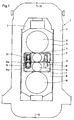
- the four-high rolling mill 1 is equipped with a device for balancing and vertical bending of the two work rolls 6, 7, which works with two double-acting hydraulic actuating cylinders 13 installed in the lower work roll chock 4 of the two roll stands 2 symmetrically to the roll axis plane 12-12.
- the actuating cylinder 13 take an actuating piston 14 to extend a piston rod 15 in the rest position 15 'from the lower work roll chock 4 and retract the free end 15a of the piston rod 15 into the upper work roll chock 5 during rolling operation and to retract the piston rod 15 from the operating position 15 ⁇ in the rest position 15 'in the lower chock 4 for separate removal of the work rolls 6, 7 when a roll change is required.
- the free end 15a thereof is fixedly connected to the upper chock 5 by means of a coupling device 16.
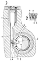
- the interior of the actuating cylinders 13 is divided by the actuating piston 14 into an upper 13a and a lower cylinder chamber 13b, and the upper cylinder chamber 13a is connected to an inlet and outlet 18 for pressure oil leading into the cylinder cover 17, and the lower cylinder chamber 13b is connected to an am Cylinder base 19 attached supply and discharge line 20 connected for pressure oil.
- the actuating piston 14 is guided against rotation on a pin 21 provided with two flattened portions, which sits centrally in the cylinder base 19.
- the piston rod 15 engages with a conical centering pin 15b arranged centrally at its free end 15a in a corresponding conical recess 22b in the lower end 22a of a shaft which is articulated in the upper chock 5 and is secured against axial displacement under tensile and compressive stress 22.
- the inner shell 23a of the spherical bearing 23 is fastened by means of a nut 24 on the upper end 22c of the shaft 22 provided with a threaded pin 22d and the outer shell 23b of the bearing 23 is fastened in the upper work roll chock 5 with a spacer sleeve 25 and a screw-in piece 26.
- a leaf spring 28 is installed as an elastic anti-rotation device for the shaft 22.
- the groove 27 in the upper shaft end 22c is of slightly spherical design, so that the leaf spring 28 can be adjusted somewhat, thereby ensuring an exact engagement of the coupling device 16 (FIG. 3).
- the bayonet-type coupling device 16 for connecting the piston rod 15 extended from the lower chock 4 into the operating position 15 ⁇ with the shaft 22 in the upper chock 5 has ring segments 29 with an external thread 30 arranged on the free end 15a of the piston rod 15 with a certain pitch.
- the coupling device 16 consists of an axially fixed coupling sleeve 31, which is rotatably mounted on the lower end 22a of the elastically rotationally secured shaft 22 and is opposite the free end 15a of the piston rod 15, and projects on the inside with the same pitch as the ring segments 29 the piston rod 15 arranged ring segments 32 with an internal thread 33 corresponding to the external thread 30 of the ring segments 29 and a rotary drive for the coupling sleeve 31 for engaging and loosening the threads 30, 33 of the ring segments 29, 32 of the piston rod 15 and the shaft 22 (FIGS. 4 and 5).
- the rotary drive of the coupling sleeve 31 is designed as a rack and pinion drive, one by one Hydraulic cylinder 34 has actuated rack 35 which is in engagement with a ring gear 36 which is fixedly seated on the coupling sleeve 31, which is arranged on the lower end 22a of the shaft 22 so as to be rotatable in the axial direction (FIG. 4).
- the engaged clutch device 16 for the fixed connection of the piston rod 15 extended from the lower chock 4 into the operating position 15 ⁇ during rolling operation with the shaft 22 articulated in the upper chock 5 is locked by the hydraulic cylinder 34.
- pressure oil is introduced via the supply line 18 into the upper cylinder chamber 13a and the lower cylinder chamber 13b is discharged via the discharge line 20
- the actuating cylinders 13 in the lower work roll chocks 4 of the two roll stands 2 of the four-high mill stand 1 cause the two work roll chocks 4, 5 in the roll stands 2 moved towards each other so that the work rolls 6, 7 are subject to a concave deflection in the vertical direction with respect to the roll gap 37.
Landscapes
- Engineering & Computer Science (AREA)
- Mechanical Engineering (AREA)
- Reduction Rolling/Reduction Stand/Operation Of Reduction Machine (AREA)
- Control Of Metal Rolling (AREA)
Applications Claiming Priority (2)
| Application Number | Priority Date | Filing Date | Title |
|---|---|---|---|
| DE4041290A DE4041290A1 (de) | 1990-12-21 | 1990-12-21 | Vorrichtung zum ausbalancieren und vertikalen biegen der arbeitswalzen eines quartowalzgeruestes |
| DE4041290 | 1990-12-21 |
Publications (2)
| Publication Number | Publication Date |
|---|---|
| EP0492134A1 EP0492134A1 (de) | 1992-07-01 |
| EP0492134B1 true EP0492134B1 (de) | 1994-08-10 |
Family
ID=6421101
Family Applications (1)
| Application Number | Title | Priority Date | Filing Date |
|---|---|---|---|
| EP91119799A Expired - Lifetime EP0492134B1 (de) | 1990-12-21 | 1991-11-21 | Vorrichtung zum Ausbalancieren und vertikalen Biegen der Arbeitswalzen eines Quartowalzgerüstes |
Country Status (4)
| Country | Link |
|---|---|
| US (1) | US5253503A (enExample) |
| EP (1) | EP0492134B1 (enExample) |
| JP (1) | JPH0755327B2 (enExample) |
| DE (2) | DE4041290A1 (enExample) |
Families Citing this family (5)
| Publication number | Priority date | Publication date | Assignee | Title |
|---|---|---|---|---|
| FR2725389B1 (fr) * | 1994-10-06 | 1996-12-27 | Clecim Sa | Installation de laminage |
| CA2287842C (en) | 1998-02-27 | 2005-03-22 | Nippon Steel Corporation | Sheet rolling method and sheet rolling mill |
| US6250120B1 (en) | 2000-06-27 | 2001-06-26 | Morgan Construction Company | Apparatus for rotatably supporting the neck of a roll in a rolling mill |
| CN112692071B (zh) * | 2020-12-11 | 2023-10-24 | 陕西龙门钢铁有限责任公司 | 一种用于对带钢四辊轧机更换工作辊的提升装置 |
| CN115318891B (zh) * | 2022-08-17 | 2025-07-11 | 中冶赛迪工程技术股份有限公司 | 一种装配式平立辊双流成型装置 |
Family Cites Families (12)
| Publication number | Priority date | Publication date | Assignee | Title |
|---|---|---|---|---|
| DE73497C (de) * | F. H. DESENISS & A. JACOB! in Hamburg, Wendenstr. 133 | Patronenhülse | ||
| DE955132C (de) * | 1954-02-03 | 1956-12-27 | Moeller & Neumann Gmbh | Vorrichtung fuer das Anpressen der Arbeitswalzen bei Walzgeruesten |
| DE1289811B (de) * | 1963-07-29 | 1969-02-27 | Achenbach Soehne Gmbh | Einrichtung zum Ausbalancieren und Durchbiegen der Arbeitswalzen eines Quartogeruestes |
| DE1527642A1 (de) * | 1966-01-26 | 1970-04-09 | Hoestemberghe & Kluetsch Gmbh | Hydraulische Anstellvorrichtung zum Konstanthalten des Walzspaltes bei Walzgeruesten,insbesondere von Block- und Brammenwalzwerken |
| DE1752581C3 (de) * | 1968-06-18 | 1974-05-09 | Bwg Bergwerk- Und Walzwerk-Maschinenbau Gmbh, 4100 Duisburg | Quarto-Walzgerüst |
| DE1936769A1 (de) * | 1969-07-19 | 1971-02-04 | Demag Ag | Vorrichtung zur Balligkeitssteuerung der Arbeitswalzen in einem Duo-Metallwalzwerk |
| DE2804007A1 (de) * | 1978-01-31 | 1979-08-02 | Schloemann Siemag Ag | Ausbalancierungs-, biege- und/oder stuetzvorrichtung fuer die arbeitswalzen von walzgeruesten |
| EP0059417B1 (de) * | 1981-02-28 | 1985-01-02 | Sms Schloemann-Siemag Aktiengesellschaft | Walzgerüst |
| JPS57181704A (en) * | 1981-04-28 | 1982-11-09 | Kawasaki Steel Corp | Roll bending device |
| JPS57181705A (en) * | 1981-05-01 | 1982-11-09 | Kawasaki Steel Corp | Roll bending device |
| DE3638330A1 (de) * | 1986-11-10 | 1988-05-19 | Schloemann Siemag Ag | Walzgeruest mit einer vorrichtung zum axialen verschieben von anstellbaren walzen |
| DE3728795A1 (de) * | 1987-08-26 | 1989-03-09 | Mannesmann Ag | Walzgeruest mit arbeitswalzen |
-
1990
- 1990-12-21 DE DE4041290A patent/DE4041290A1/de active Granted
-
1991
- 1991-11-21 DE DE59102500T patent/DE59102500D1/de not_active Expired - Fee Related
- 1991-11-21 EP EP91119799A patent/EP0492134B1/de not_active Expired - Lifetime
- 1991-12-17 US US07/808,769 patent/US5253503A/en not_active Expired - Fee Related
- 1991-12-20 JP JP3337367A patent/JPH0755327B2/ja not_active Expired - Lifetime
Also Published As
| Publication number | Publication date |
|---|---|
| US5253503A (en) | 1993-10-19 |
| JPH0755327B2 (ja) | 1995-06-14 |
| EP0492134A1 (de) | 1992-07-01 |
| DE4041290C2 (enExample) | 1993-05-06 |
| JPH0523716A (ja) | 1993-02-02 |
| DE4041290A1 (de) | 1992-07-02 |
| DE59102500D1 (de) | 1994-09-15 |
Similar Documents
| Publication | Publication Date | Title |
|---|---|---|
| DE2540269B2 (de) | Einstellbare Stützvorrichtung für die Loswalze einer Walzenmühle | |
| EP0455082A1 (de) | Kombinierte Feinstahl- und Drahtstrasse | |
| EP1102646A1 (de) | Fräsgerät für die rohrreinigungs- und rohrsanierungstechnik | |
| DE2842529C2 (de) | Walzwerkgerüst zum Kaltwalzen von Rohren | |
| DE7935975U1 (de) | Vorrichtung zum spannen und loesen eines konischen schaftes eines werkzeuges oder eines zusatzaggregates an werkzeugmaschinen, insbesondere bohr- und fraesmaschinen | |
| DE9402242U1 (de) | Meißelhalter mit einer lösbar festgelegten Meißelbüchse | |
| DE2848440C2 (de) | Walzgerüst | |
| DE4041290C2 (enExample) | ||
| DE1475505A1 (de) | Schiebehuelse fuer Zapfenkupplungen | |
| EP4243998A1 (de) | Lagerbefestigungssystem und verfahren zum aufziehen, halten und abziehen einer lagereinheit auf einem zapfen einer walze | |
| EP3233287B1 (de) | Brecheinrichtung | |
| EP0324978B1 (de) | Walzwerksantrieb mit zwischen Kammwalzen und Arbeitswalzen lösbar angeordneten Gelenkspindeln | |
| DE2243312A1 (de) | Kreiselbrecher | |
| EP2654980A1 (de) | Lageranordnung und walzeinheit für eine walzwerkswalze | |
| DE4442568A1 (de) | Breitenverstellbare Horizontalwalze für ein Universalwalzgerüst | |
| EP1754556B1 (de) | Vorrichtung für ein schnelles Verbinden oder ein schnelles Lösen von zwei grossen, schweren Bauteilen für den Hüttenwerksbetrieb, insbesondere für ein Stahl-Stranggiessmaschine | |
| EP0035164B1 (de) | Kraftschrauber | |
| EP0734794B1 (de) | Walzgerüst mit Stütz- und Arbeitswalzen zum Walzen von Blechen und Bändern | |
| DE2326140C3 (de) | Vorrichtung zum radialen Anstellen und zur Vermeidung von Überlast der Walzen von Duo-Walzgerüsten | |
| EP2158047B1 (de) | Mehrteilige walze | |
| DE2219941C3 (de) | Dreiwalzen - Schrägwalzwerk zur Herstellung von Rohren, vorzugsweise zur Herstellung von dünnwandigen Rohren mit verdickten Enden | |
| CH698771A2 (de) | Bohrantriebseinheit für ein Doppelbohrgestänge. | |
| EP0293583B1 (de) | Vorrichtung zum axialen Verschieben von Walzen in Walzgerüsten | |
| DE2027538A1 (de) | Vielwalzengerüst mit fliegend gelagerten Walzen | |
| DE3050546T5 (en) | Device for fixing the armour on the adjusting ring of a cone breaker |
Legal Events
| Date | Code | Title | Description |
|---|---|---|---|
| PUAI | Public reference made under article 153(3) epc to a published international application that has entered the european phase |
Free format text: ORIGINAL CODE: 0009012 |
|
| AK | Designated contracting states |
Kind code of ref document: A1 Designated state(s): DE FR GB IT |
|
| 17P | Request for examination filed |
Effective date: 19921124 |
|
| 17Q | First examination report despatched |
Effective date: 19930701 |
|
| GRAA | (expected) grant |
Free format text: ORIGINAL CODE: 0009210 |
|
| AK | Designated contracting states |
Kind code of ref document: B1 Designated state(s): DE FR GB IT |
|
| REF | Corresponds to: |
Ref document number: 59102500 Country of ref document: DE Date of ref document: 19940915 |
|
| GBT | Gb: translation of ep patent filed (gb section 77(6)(a)/1977) |
Effective date: 19940818 |
|
| ITF | It: translation for a ep patent filed | ||
| ET | Fr: translation filed | ||
| PLBE | No opposition filed within time limit |
Free format text: ORIGINAL CODE: 0009261 |
|
| STAA | Information on the status of an ep patent application or granted ep patent |
Free format text: STATUS: NO OPPOSITION FILED WITHIN TIME LIMIT |
|
| 26N | No opposition filed | ||
| PGFP | Annual fee paid to national office [announced via postgrant information from national office to epo] |
Ref country code: FR Payment date: 20011016 Year of fee payment: 11 |
|
| PGFP | Annual fee paid to national office [announced via postgrant information from national office to epo] |
Ref country code: GB Payment date: 20011121 Year of fee payment: 11 |
|
| REG | Reference to a national code |
Ref country code: GB Ref legal event code: IF02 |
|
| PGFP | Annual fee paid to national office [announced via postgrant information from national office to epo] |
Ref country code: DE Payment date: 20020124 Year of fee payment: 11 |
|
| PG25 | Lapsed in a contracting state [announced via postgrant information from national office to epo] |
Ref country code: GB Free format text: LAPSE BECAUSE OF NON-PAYMENT OF DUE FEES Effective date: 20021121 |
|
| PG25 | Lapsed in a contracting state [announced via postgrant information from national office to epo] |
Ref country code: DE Free format text: LAPSE BECAUSE OF NON-PAYMENT OF DUE FEES Effective date: 20030603 |
|
| GBPC | Gb: european patent ceased through non-payment of renewal fee | ||
| PG25 | Lapsed in a contracting state [announced via postgrant information from national office to epo] |
Ref country code: FR Free format text: LAPSE BECAUSE OF NON-PAYMENT OF DUE FEES Effective date: 20030731 |
|
| REG | Reference to a national code |
Ref country code: FR Ref legal event code: ST |
|
| PG25 | Lapsed in a contracting state [announced via postgrant information from national office to epo] |
Ref country code: IT Free format text: LAPSE BECAUSE OF NON-PAYMENT OF DUE FEES;WARNING: LAPSES OF ITALIAN PATENTS WITH EFFECTIVE DATE BEFORE 2007 MAY HAVE OCCURRED AT ANY TIME BEFORE 2007. THE CORRECT EFFECTIVE DATE MAY BE DIFFERENT FROM THE ONE RECORDED. Effective date: 20051121 |