EP0488324A2 - Verfahren und Vorrichtung zur Herstellung von Halbtonbildern - Google Patents
Verfahren und Vorrichtung zur Herstellung von Halbtonbildern Download PDFInfo
- Publication number
- EP0488324A2 EP0488324A2 EP91120447A EP91120447A EP0488324A2 EP 0488324 A2 EP0488324 A2 EP 0488324A2 EP 91120447 A EP91120447 A EP 91120447A EP 91120447 A EP91120447 A EP 91120447A EP 0488324 A2 EP0488324 A2 EP 0488324A2
- Authority
- EP
- European Patent Office
- Prior art keywords
- conversion
- conversion functions
- functions
- number value
- values
- Prior art date
- Legal status (The legal status is an assumption and is not a legal conclusion. Google has not performed a legal analysis and makes no representation as to the accuracy of the status listed.)
- Granted
Links
Images


Classifications
-
- H—ELECTRICITY
- H04—ELECTRIC COMMUNICATION TECHNIQUE
- H04N—PICTORIAL COMMUNICATION, e.g. TELEVISION
- H04N1/00—Scanning, transmission or reproduction of documents or the like, e.g. facsimile transmission; Details thereof
- H04N1/40—Picture signal circuits
- H04N1/405—Halftoning, i.e. converting the picture signal of a continuous-tone original into a corresponding signal showing only two levels
- H04N1/4055—Halftoning, i.e. converting the picture signal of a continuous-tone original into a corresponding signal showing only two levels producing a clustered dots or a size modulated halftone pattern
- H04N1/4058—Halftoning, i.e. converting the picture signal of a continuous-tone original into a corresponding signal showing only two levels producing a clustered dots or a size modulated halftone pattern with details for producing a halftone screen at an oblique angle
Definitions
- the present invention relates to a method of and an apparatus for obtaining a halftone image from an original image having gradation with an image recording apparatus such as a scanner.
- moire may occur due to interference between a regular pattern and a halftone dot, which is well-known.
- Japanese Patent Laying Open Gazette No. 2-136255 (1990) discloses a method of reducing such moire.
- a large number of conversion functions (about thirty kinds, preferably) must be prepared in order to obtain a halftone image of a good quality and with less moire.
- Either the screen pattern or the image signal is converted through each of these conversion functions, thereafter the corresponding imaginary solid-pixel numbers are computed.
- comparisons are required between each of the computed imaginary solid-pixel numbers and the reference solid-pixel number. Accordingly, a hardware of a significantly large scale is required in order to carry out this series of processings, that is a problem in the conventional method.
- the method comprises the steps of: (a) obtaining screen pattern data consisting of threshold values; (b) preparing three or more conversion functions having a predetermined correlation therebetween; (c) selecting only a part of the conversion functions to obtain two or more provisional conversion functions; (d) generating an image signal representing an original image for each pixel; and (e) defining an array of unit areas on the photosensitive material and dividing each unit area into a plurality of divided areas.
- Counted in another step (g) is the number of second recorded pixels expected to be obtained in each divided area if a halftone dot image is recorded on the photosensitive material as a function of the image signal at a second halftone dot pitch corresponding to a size of each divided area, to thereby obtain a reference number value.
- the image signal is converted in the step (j) through the one of the conversion functions to obtain a converted image signal.
- the converted image signal is compared with the threshold values to obtain the control signal in the step (k); and the photosensitive material is exposed to the light while modifying the light in accordance with the control signal to obtain a halftone dot image on the photosensitive material, in the step (1).
- the step (a) comprises the steps of: (a-1) obtaining the screen pattern data as first screen pattern data consisting of first periodic threshold values having a first period proportional to the first halftone dot pitch; and (a-2) obtaining second screen pattern data consisting of second periodic threshold values having a second period proportional to the second halftone dot pitch.
- the step (g) may comprise the step of: (g-1) comparing the image signal with the second periodic threshold values in each divided area to obtain the reference number value.
- conversion lines representative of the conversion functions are defined in a rectangular region having four apexes of: (0, 0), (0,A), (A, 0) and (A, A) on a two-dimensional conversion coordinate plane such that each conversion lines connects diagonal two apexes within the four apexes, where A is a non-zero value.
- the conversion lines may be such that the conversion lines intersect a straight line connecting the diagonal two apexes, wherein respective intersections of the conversion lines and the straight line are aligned on the straight line at a same interval.
- the conversion lines representative of the conversion functions consist of a straight conversion line connecting the diagonal apexes, and one or more pairs of conversion curves connecting the diagonal two apexes, wherein each pair of conversion curves are substantially symmetrical with respect to the straight line.
- an object of the present invention is to provide a method and an apparatus with which scale of a hardware can be reduced.
- Another object of the present invention is to provide a method and an apparatus with which a halftone image with extremely less moire can be produced.
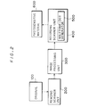
- Fig. 2 is a schematic block diagram showing a scanner to which a preferred embodiment of the present invention is applied.
- an image of an original 100 is read for each pixel by a reading scanner unit 200.
- An image signal thus obtained is transferred to an image processing unit 300.
- the image processing unit 300 performs processings such as gradation setting and contour enhancement on the inputted image signal.
- the processed image signal is led to a recording scanner unit 400.
- the recording scanner 400 comprises a halftone-dot generator 500 of which function will be described later.
- the recording scanner unit 400 performs processings, which will be also described later, on either image signal or a screen threshold pattern, and thereafter converts the image signal into a halftone-dot signal.
- the recording scanner unit 400 records a halftone image on a photosensitive material (a surface-to-be-scanned) 600 by exposing the photosensitive material 600.
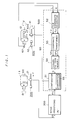
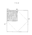
- Fig. 1 illustrates respective detail structures of the above-described blocks shown in Fig. 2.
- An original 100 is mounted on an original drum 11, so that it is rotated in the direction q).
- a scanning head 21 moves in the direction Y so as to scan the original 100 for each scanning line, thereby an image signal OS is obtained.
- the image signal OS is led to an image processing unit 300 to be subjected to prescribed processings therein such as color correction and gradation setting, and thereafter outputted as a processed image signal PS.
- the processed image signal PS is inputted in a comparator 51 in the halftone-dot signal generator 500 to be subjected to a conversion processing, which will be described later, and thereafter outputted as an exposure control signal QS.
- a recording head 41 modulates an exposure beam for recording in response to the exposure control signal QS. Then, the recording head 41 radiates the modulated exposure beam on the photosensitive material 600 which is mounted on a recording drum 61 and rotated in the direction q).
- a rotary encoder 62 is coupled to the recording drum 61, and outputs a position signal K concerning a main scanning direction X.
- Another rotary encoder 42 is coupled with a feed screw which moves the recording head 41, and outputs a position signal L concerning to a subscanning direction Y.
- Both the position signals K and L are inputted in a film coordinate generator 52 in the halftone-dot generator 500, and outputted as film coordinates F x , Fy, respectively, which indicate the position of a pixel subjected to exposure on the photosensitive material 600.
- the film coordinates F x , Fy are inputted to a coordinate transformer 53 to be subjected to coordinate transformation, which will be described later. This coordinate transformation is required for setting a screen angle.
- the film coordinates F x , Fy are transformed to be outputted as screen pattern coordinates SP x , SP Y .
- the screen pattern coordinates SP x , SPy serve as address signals in accessing a screen pattern memory 54.
- a screen threshold value D is read out from the screen pattern 54 of which address has been assigned, and is inputted to the comparator 51.
- a converter 55 is provided in the comparator 51, and converts either the screen threshold value D or the above-described processed image signal PS. This conversion processing will be described later. Then, the threshold value D is compared with the processed image signal PS (either one has been converted), and thereafter the exposure control signal QS is outputted in response to the comparison result, as described above.
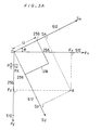
- the film coordinates F x , Fy are obtained in response to the position signals K and L. Respective single scales of the film coordinate axes F x , Fy correspond to a single-side length P of an exposure pixel PX.
- the exposure pixel of a square shape is shown in Fig. 3A.
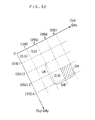
- Figs. 3A to 3C illustrates a series of coordinate transformation operations.
- the film coordinates F x , Fy are transformed into screen coordinates S x , Sy.
- the film coordinate axes F x , Fy and the screen coordinate axes S x , Sy have a common origin, and the latter are shifted from the former by an angle ⁇ .
- An array of unit areas or unit blocks UB is defined on the screen coordinates S x , Sy .
- This unit block UB corresponds to a unit halftone-dot block on the surface-to-be-scanned employed in exposure.
- a symbol U is defined for expressing the single-side length of the unit halftone-dot block UB.
- Coordinate transformation from the film coordinates F x , Fy to the screen coordinates S x , Sy can be achieved by rotating the coordinate axes by the angle ⁇ and contracting or extending the axes. It is well known that the screen coordinates S x , Sy are given by the following equation (1):
- the screen coordinates S x , Sy are then transformed to the screen pattern coordinates SP x , SP Y .
- the screen pattern coordinates SP x , SPy are defined within a single unit halftone-dot block UB. Therefore, the screen pattern coordinates SP x , SPy have coordinate values in the range between 0 and 255. The coordinate values are regularly repeated in this range on the screen coordinates S x , Sy.
- A is divided by B, the remainder is expressed by A • modB, wherein the screen pattern SP x , SPy are given by the following equation (3):
- quarter halftone-dot blocks (divided areas) QB are defined, in which each quarter halftone-dot block QB has a size equal to one-fourth the size of the unit halftone-dot block UB.
- the quarter halftone-dot block QB can be obtained by dividing the unit halftone-dot block UB into four squares congruous to each other.
- Coordinates QB X , QBy of the quarter halftone-dot block QB are obtained by disregarding the least significant seven bits of the screen coordinates S x , Sy and by basing the more significant bits thereof, i.e., the eighth bit and more, as shown in Fig. 3C.
- the conversion transformation in the coordinate transformer 53 is completed through the above-described procedure.
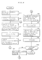
- FIG. 4 is a flow chart showing the procedure in the processings of converting a processed image signal PS into a converted image signal RS through actually conducting an exposure processing.
- a plurality of conversion functions G i are established.
- Various functions can be employed as the conversion functions G i .
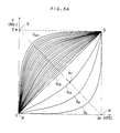
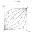
- the functions shown in Fig. 5A are employed as the conversion functions G i in the present preferred embodiment.
- Conversion functions G 1 to G 7 , Gs to G 15 and G 17 to G 23 are not shown in the figure for the purpose of avoiding complicatedness. These functions G 1 to G 7 , G 9 to G 15 and G 17 to G 23 correspond to the functions obtained by reflecting conversion functions G 47 to G 41 , G 39 to G 33 , and G 31 to G 25 , respectively, at a plane of mirror symmetry which is a plane vertical to a plane XY on which a conversion function G 24 is included.
- the horizontal axis X represents a processed image signal PS
- the vertical axis Y represents a converted image signal RS.
- the conversion function G i is defined within the following range:
- the number of the conversion functions G i may be arbitrarily increased or decreased as required.
- all the conversion functions G i includes common two points, i.e., P(0, 0) and Q(2a, 2a).
- the conversion function G 24 is an identical function for converting the processed image signal PS into the converting image signal RS 24 in a ratio of 1 to 1.
- the other conversion functions Go to G 23 and G 25 to G 48 are symmetrical with respect to the straight line SR which includes two points S (0, 2a) and R (2a, 0).
- An intersection of the conversion function G i and the straight line SR is expressed by the symbol N i .
- Each interval between each adjacent two intersections N i and N i-1 or N i and N i+1 is constant.
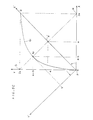
- Fig. 5C shows the relations between the conversion function G i (the conversion function G 24 is exception) shown in Fig. 5A and coordinate axes X' and Y' which are obtained by rotating the coordinate axes X and Y shown in Fig. 5A by 45 in the counterclockwise direction with the rotation center at the point P.
- the conversion function G i is a parabola with the vertex at the intersection N i with respect to the coordinate axes X' and Y'.
- N i positional coordinates of the intersection N i with respect to the coordinate axes X and Y are expressed as N i (a - b, a + b), while those with respect to another coordinate axes X' and Y' are expressed as N i (a', b').
- the functional form of the conversion function G i can be given by following equations (7) to (11), wherein the symbol b is a parameter.
- the functional form of the conversion function G can be established by holding the relations defined by these equations (7) to (11) in a memory.
- the conversion function G can be established by designating coordinate values (X, Y) to be included in the conversion function G i as table values, or by designating the parameter b.
- the conversion functions G i in the above-described preferred embodiment are the curves which are symmetrical with respect to the straight line RS, wherein respective second differential coefficients d 2 Y/dX 2 are always positive or always negative.
- the conversion functions G are not limited to such curves.
- Broken lines shown in Fig. 5D which are symmetrical with respect to the straight line SR may also be employed as the conversion functions G ; . Only main broken lines are shown in Fig. 5D for the purpose of avoiding complicatedness.
- a plurality of the conversion functions are extracted among the conversion functions G i established in the preceding step S11. These extracted functions are hereafter referred to as provisional conversion functions F,.
- the number of the provisional conversion functions F i to be extracted is arbitrary as long as it is smaller than the number of the conversion functions G ; .
- provisional conversion functions F j are extracted, as shown in Fig. 5B.
- the relation between the conversion functions G i and the provisional conversion functions F j can be expressed as follows, where the symbol j is an integer:
- the steps S13 to S21 correspond to exposure scanning processes.
- a reference solid-pixel number N ST in response to the given processed image signal PS is computed for one quarter halftone-dot block QB on the scanning line.
- the subsequent steps S14 to S19 correspond to a series of processings conducted for this one quarter halftone-dot block QB.
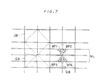
- Fig. 7 shows an example of reproducing a narrow line ML indicating a halftone-dot area ratio of 50 % on a unit halftone-dot block UB having a normal screen threshold pattern SP1 shown in Fig. 6.
- Fig. 6 shows the screen threshold pattern on the quarter halftone-dot block QB.
- Screen threshold values D in the other three quarter halftone-dot blocks QB are arranged to be symmetrical to the pattern shown in Fig. 6 with respect to the center of the unit halftone-dot block UB.
- Dynamic range of the screen threshold value D is between 0 to 63. Accordingly, the screen threshold value D in the solid portion with a halftone-dot area ratio of 50 % falls in the range of D 31.
- each quarter halftone-dot block QB on which the narrow line ML passes is 25 % in a solid halftone-dot area percentage.
- the actual solid halftone-dot area ratio is only 12.5 %.
- Exposed solid portions are represented by the symbols BP1 to BP4. Consequently, a certain measure is required to ensure designated halftone-dot area ratio in processing images such as the narrow line ML.
- a solid-pixel numbers N BP to be exposed within each quarter halftone-dot block QB is determined by applying the following equation (15) to each quarter halftone-dot block QB:
- the numeral PS av represents an average value of image signals given for each pixel in each quarter halftone-dot block QB, and is obtained by averaging the image signals. Each of the image signals has a dynamic range of 0 to 255.
- the numeral N TOT represents the total pixel number within each quarter halftone-dot block QB.
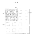
- the solid-pixel numbers N BP in each of the quarter halftone-dot blocks QB may be computed as shown in Fig. 9 by applying a screen threshold patterns SP2 of a short period shown in Fig. 8 without employing the above-described computing method, thereby solid-pixel numbers for providing required halftone-dot area ratio may be obtained.
- the solid portions BP are arranged in more uniformity on the unit halftone-dot block UB, so that such an approximation can be carried out.
- the solid portion BP occupies approximate 25 % of the quarter halftone-dot block QB on which the narrow line ML passes.
- the solid-pixel numbers N BP thus obtained are memorized as the reference solid-pixel numbers N ST of the corresponding quarter halftone-dot blocks QB.
- the converted image signal RS j is obtained for the said one quarter halftone-dot block QB on the function of the corresponding provisional conversion function F j .
- a imaginary solid-pixel number N Rsj to be formed on the basis of the converted image signal RS j is computed for the said one quarter halftone-dot block QB by means of imaginary exposure, which will be more fully described later.
- the imaginary solid-pixel number N Rsj is compared with the reference solid-pixel number N ST for the said one quarter halftone-dot block QB, to thereby presume a conversion function G j , which gives the solid-pixel number most approximate to the reference solid-pixel number N sT , among the conversion functions G i .
- the conversion function G J is defined as a most-approximate conversion function H QB for the said one quarter halftone-dot block QB.
- the most-approximate conversion function H QB is a function which interpolates the functions G 16 and G 24 .
- the conversion function G i to serve as the most-approximate conversion function H QB can be presumed by linear interpolation, as described below.
- Fig. 10 shows the relations between the imaginary solid-pixel numbers N Rs2 (a first interpolating solid-pixel number) and N Rs3 (a second interpolating solid-pixel number) and the conversion functions G 16 to G 24 .
- the difference between the imaginary solid-pixel numbers N Rs2 and N Rs3 is divided into eight equal parts, so that seven interpolation imaginary solid-pixel numbers N Rs21 to N Rs27 interpolating the imaginary solid-pixel numbers N Rs2 and N Rs3 are shown on the horizontal axis.
- the conversion function G 19 corresponds to the conversion function G j , which gives the solid-pixel number most approximate to the reference solid-pixel number N ST satisfying the equations (18) and (19). That is, the relation between the most-approximate conversion function H QB and the conversion function G 19 can be expressed as follows:
- the process is proceeded to the step S17.
- the processed image signal PS is converted through the most-approximate conversion function H QB , thereby the converted image signal RS is obtained:
- step S18 the converted image signal RS is compared with the screen threshold value D, thereby the exposure control signal QS is produced.
- step S19 exposure is carried out for the said one quarter halftone-dot block QB in response to the exposure control signal QS.
- step S20 it is judged whether or not the current scanning position is a position of an exposure terminal.
- the processing is turned to next quarter halftone-dot block QB (the step S21), and the series of processings corresponding to the steps S13 to S19 is carried out again for the new quarter halftone-dot block QB.
- Fig. 11A illustrates an example wherein a narrow line ML indicating a halftone-dot area ratio of 50% is exposed without performing conversion processing
- Fig. 11 B shows an example wherein the same line ML is exposed after the above-described conversion processing is carried out.
- solid portions BP are represented by regions R1 to R7 with circles.
- the regions R1 to R7 have respective areas significantly different from each other.
- the regions R1 to R7 have areas approximately equal to each other, respectively. Namely, in the example shown in Fig.
- the area of the solid portions BP is too small in the regions R1 to R3, and excessive in the regions R5 and R7.
- the area of the solid portions BP turns to be larger in the regions R1 to R3, and turns to be smaller in the regions R5 to R7 through the conversion processing.
- the area of the solid portion BP is proper, and therefore is hardly changed. The area of the solid portions BP is thus adjusted properly for each halftone-dot.
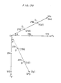
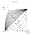
- Fig. 12A shows conversion functions g ; for converting the screen threshold value D corresponding to the conversion functions G ; shown in Fig. 5A.
- the horizontal axis represents the screen threshold values D
- the vertical axis represents the converted screen threshold values TD ; .
- conversion functions gi to g 7 , g 9 to g 15 , and g 17 to g 22 are not shown in Fig. 12A for the purpose of avoiding complicatedness.
- Fig. 12B shows provisional conversion functions f j for converting the screen threshold value D corresponding to the provisional conversion functions F j shown in Fig. 5B.
- the relations between the conversion functions g i and the provisional conversion functions f j are similar to the above-described relations between the conversion functions G i and the provisional conversion functions F j , and can be expressed as follows:
- the screen threshold value D is converted into the converted screen threshold value TD j through the conversion functions f j .
- imaginary solid-pixel numbers N TDj are computed as a function of the converted screen threshold values TD j for each quarter halftone-dot block QB.
- Each of the computed imaginary virtual solid pixel numbers N TDj are compared with the reference solid-pixel number N sT , thereby the most-approximate conversion function H QB is presumed among the conversion functions g i .
- This procedure is similar to that of the above-described conversion processing for converting the processed image signal PS.
- the screen threshold value D is converted through the most-approximate conversion function H QB which has been obtained through the above-described procedure, and then, the converted screen threshold value TD is compared with the processed image signal PS, thereby an exposure control signal QS' is produced. Similar to the above-described conversion processing for converting the processed image signal PS, errors in halftone-dot area ratio can be restricted by performing exposure in response to the exposure control signal QS'.
- the imaginary solid-pixel numbers N Rsj by converting the processed image signal PS through a plurality of the provisional conversion functions F j for each divided halftone-dot block.
- imaginary exposure is performed with an imaginary beam in the present preferred embodiment.
- the imaginary solid-pixel numbers N Rsj during this imaginary exposure are computed for each quarter halftone-dot block QB, and the computed numbers N Rsj are stored in a memory to be used in actual exposure.
- the reference solid-pixel number N ST is also calculated by the similar imaginary exposure for each quarter halftone-dot block QB, and the calculated numbers are stored in the memory.
- the imaginary virtual beam precedes the actual exposure beam by at least a diagonal length of the quarter halftone-dot block QB in a subscanning line Y (see Fig. 1). Accordingly, the reference solid-pixel number N ST and the imaginary solid-pixel number N RS have been already calculated for the quarter halftone-dot block QB on which the actual exposure beam is scanning.
- the imaginary beam precedes the actual exposure beam by n pixels in the subscanning direction Y.
- the value of n is selected to be the smallest integer satisfying the condition that a product of n and P is greater than the length of the diagonal of the quarter halftone-dot block QB, where P indicates the length of one side of the pixel PX shown in Fig. 3A.
- the memory for storing the reference solid-pixel number N ST and the imaginary solid-pixel numbers N RSj for each quarter halftone-dot block QB has the capacity to store all those numbers N ST and N sTj for all the quarter halftone-dot blocks QB on the entire surface of the film 600 (see Fig. 1).
- the above-described memory has flag bit of one bit in addition to the stored bits of the imaginary solid-pixel numbers N Rsj and the reference solid-pixel number N sT .
- the function of this flag in calculation of the reference solid-pixel number N ST and the imaginary solid-pixel numbers N RSj is to clear the contents of the memory into 0 for a new quarter halftone-dot block QB, so that solid-pixel numbers for the new quarter halftone-dot block QB can be calculated.
- Fig. 13 is a block diagram showing the halftone-dot generator 500 having a digital-circuit structure according to a preferred embodiment of the present invention, in which the processed image signal PS is converted.
- the quarter halftone-dot block coordinates QB x , QBy for actual exposure and the screen pattern coordinates SP x , SPy for actual exposure are calculated in a hardware controller CON as a function of the film coordinates F x , Fy of the exposure beam.
- Quarter halftone-dot block coordinates AQB x , AQBy for imaginary exposure and screen pattern coordinates ASP x , ASPy for imaginary exposure are also calculated in the hardware controller CON as a function of the film coordinates F x , F (y+n) of the imaginary beam.
- a pixel memory PXM comprises memory elements M o to M 7 .
- the memory elements Mo to M 6 store the imaginary solid-pixel numbers N RSj , which are obtained as a function of the converted image signals RS j converted through the provisional conversion functions F j shown in Fig. 5B, respectively.
- the memory element M 7 stores the reference solid-pixel number N ST .
- all flags for the memory elements M o to M 7 are set to 0 in response to a memory control signal MCO prior to exposure scanning.
- a first selector SEL1 selects the quarter halftone-dot block coordinates AQB X , AQBy for imaginary exposure in response to a first select signal SS1.
- the quarter halftone-dot block coordinates AQB X , AQBy serve as an address ADR of the pixel memory PXM.
- the memory element M o is read out in response to the address ADR.
- a fourth selector SEL4 selects "0" when a flag output FOU is “0". When the flag output FOU is "1 ", the fourth selector SEL4 selects the output DOU which is read out from the memory element M o . The selected value "0" or the selected output DOU is inputted to an adder ADD.
- a second selector SEL2 selects the screen pattern coordinates ASP x , ASPy for imaginary exposure in response to said first select signal SS1 and outputs the same.
- the screen pattern coordinates ASP x , ASPy serve as an address of a screen threshold memory SPM.
- This memory SPM stores a first periodic threshold pattern SP1 having a normal repetition period corresponding to the halftone dot pitch proportional to the size of the unit halftone-dot block UB, and a second periodic threshold pattern SP2 having a short repetition period corresponding to the halftone dot pitch proportional to the size of the quarter halftone-dot block QB.
- periodic threshold pattern is used to represent not only a pattern including a plurality of unit periodic patterns but also a pattern having only one unit pattern which is repeatedly read out from the memory to generate a periodic pattern.
- the first threshold pattern SP1 is selected in the first place, and the screen threshold value D of the first threshold pattern SP1 is outputed.
- a third selector SEL3 selects a conversion control signal CCO generated from the hardware controller CON in response to a third select signal SS3, and supply the same to said pixel memory PXM and a converter COV.
- the processed image signal PS is converted through the provisional conversion function Fo in response to the conversion control signal CCO, and outputs the converted signal as a converted image signal RSo.
- the image signal PS is read out from an image memory PIM in response to an image memory control signal PCO.
- the converter COV may be easily constructed as a memory of look- up table type.
- the converted image signal RSo thus obtained and the screen threshold value D are inputed to the comparator COM to be compared with each other therein.
- the comparator COM When the converted image signal RSo is equal to or larger than the screen threshold value D (RS 0 ⁇ D), the comparator COM outputs "1 ". When this condition is not satisfied, the comparator COM outputs "0". The output is supplied to the adder ADD.
- This adder ADD performs the addition, and outputs DIN. Based on the output DIN, the memory element Mo is rewritten. At the same time, a flag controller FCO supplies a flag input having a value of "1 ", thereby the flag of the memory element Mo is set at "1 ".
- Renewal of the memory element M 7 i.e., calculation of the reference solid-pixel number N ST -(corresponding to the step S13 in Fig. 4) is also performed in the similar manner.
- the processed image signal PS is converted through the provisional conversion function F 3 . That is, the processed image signal PS is not converted.
- the second threshold pattern SP2 having a short repetition cycle is selected among the two patterns SP1 and SP2 of the screen threshold memory SPM.
- the first select signal SS1 is switched, and the first selector SEL1 selects the quarter halftone-dot block coordinates QB X , QBy for actual exposure, and employs the same as the address ADR of the pixel memory PXM.
- the imaginary solid-pixel numbers N Rsj are sequentially read out from the memory elements M o to M 6 , and then, the reference solid pixel number N ST is read out from the memory element M 7 .
- the imaginary solid-pixel numbers N Rsj and the reference solid-pixel number N ST are stored in resisters Lo to L 7 , in synchronism with a latch pulse LAP. At this time, each of the flags in the pixel memory PXM is rewrittened to "0".
- an optimum function presuming circuit FDC When the resisters Lo to L 7 are filled with the data N Rsj and N ST , an optimum function presuming circuit FDC operates in response to a starting pulse STP.
- the optimum function presuming circuit FDC outputs a distinguish signal J for specifying a conversion function which is presumed to give the solid-pixel number most approximate to the reference solid-pixel number N ST .
- This distinguish signal J is obtained by linear interpolation as follows:
- the function INT(x) converts a real number x into an integer, wherein fraction of .5 and over is counted as one and the rest is cut away.
- the distinguish signal J is determined by the following equations (30) or (31):
- the distinguish signal J thus determined is supplied to the third selecter SEL3.
- the third select signal SS3 is switched, thereby the distinguish signal J is selected in the third selecter SEL3 to be inputted in the converter COV.
- the corresponding conversion function G j is selected as the most-approximate conversion function H QB (the step S16 in Fig. 4).
- the processed image signal PS is converted through the selected conversion function G j (the step S17 in Fig. 4), and the converted image signal RS is inputted to the comparator COM.
- the second selecter SEL2 selects the screen pattern coordinates SP x , SPy for actual exposure and outputs the same.
- the coordinates SP x , SPy serve as an address, thereby the screen threshold value D is read out from the first threshold pattern SP1 to be inputted to the comparator COM.
- the output of the comparator COM is latched in a latch circuit LAT in synchronism with a latch control signal LCO, and then, led to the recording scanner unit 400 as the expose control signal QS.
- the steps S11 through S18 in Fig. 4 are thus completed.
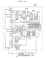
- Fig. 14 is a block diagram showing a circuit structure of the halftone generator 500, wherein the screen threshold value D is converted.
- the processed image signal PS is inputted directly from the image memory PIM to the comparator COM.
- the screen threshold value D from the screen threshold memory SPM is converted into a converted screen threshold value TD in the converter COV, and thereafter inputted to the comparator COM.
- the converter COV stores the conversion functions g ; shown in Fig. 12A and the provisional conversion functions f j shown in Fig. 12B.
- Other structures and operations are similar to those in the example shown in Fig. 13 wherein the image signal PS is converted.
- An image signal OS obtained by a reading scanner unit 200 is inputted to a CPU 71 to be converted into a processed image signal PS.
- This processed image signal PS is temporarily stored in a disk 72.
- the processed image signal PS is read out from the disk 72 to be subjected to the above-described processings in the hardware circuit in the CPU 71 according to a programming corresponding to the flow chart in Fig. 4.
- the processed image signal PS is thus converted into a converted image signal RS in the CPU 71.
- the converted image signal RS outputted from the CPU 71 is stored in another disk 73.
- the converted image signal RS is read out from the disk 73 as required, and converted into an exposure control signal QS to be supplied to a recording scanner unit.
- Calculation and exposure may thus be independently conducted.
Applications Claiming Priority (2)
| Application Number | Priority Date | Filing Date | Title |
|---|---|---|---|
| JP331246/90 | 1990-11-28 | ||
| JP2331246A JP2517793B2 (ja) | 1990-11-28 | 1990-11-28 | 網目版画像形成方法 |
Publications (3)
| Publication Number | Publication Date |
|---|---|
| EP0488324A2 true EP0488324A2 (de) | 1992-06-03 |
| EP0488324A3 EP0488324A3 (en) | 1993-06-16 |
| EP0488324B1 EP0488324B1 (de) | 1997-05-28 |
Family
ID=18241536
Family Applications (1)
| Application Number | Title | Priority Date | Filing Date |
|---|---|---|---|
| EP91120447A Expired - Lifetime EP0488324B1 (de) | 1990-11-28 | 1991-11-28 | Verfahren und Vorrichtung zur Herstellung von Halbtonbildern |
Country Status (4)
| Country | Link |
|---|---|
| US (1) | US5268772A (de) |
| EP (1) | EP0488324B1 (de) |
| JP (1) | JP2517793B2 (de) |
| DE (1) | DE69126279T2 (de) |
Cited By (5)
| Publication number | Priority date | Publication date | Assignee | Title |
|---|---|---|---|---|
| EP0571010A1 (de) | 1992-05-22 | 1993-11-24 | Agfa-Gevaert N.V. | Verbessertes Verfahren zur frequenzmodulierten Halbtonrasterung |
| EP0813335A2 (de) * | 1996-06-12 | 1997-12-17 | Fuji Photo Film Co., Ltd. | Verfahren zur Erzeugung von Gradationskorrigierten Bilddaten, Bildwiedergabegerät, und Verfahren zur Berechnung der Belichtungsmenge |
| EP0859508A2 (de) * | 1997-02-13 | 1998-08-19 | Fujitsu Limited | Halbtondarstellung unter Berücksichtigung der Bild- und Druckereigenschaften |
| WO2001050236A1 (en) * | 2000-01-03 | 2001-07-12 | Array Ab Publ. | Printing device and method |
| US7455510B2 (en) | 2001-08-13 | 2008-11-25 | Oakey Edwin J | Apparatus for forming high-impact transparent, distortion-free polymeric materials |
Families Citing this family (3)
| Publication number | Priority date | Publication date | Assignee | Title |
|---|---|---|---|---|
| JP3698541B2 (ja) * | 1998-02-16 | 2005-09-21 | 株式会社沖データ | 擬似階調画像処理装置 |
| US6373594B1 (en) * | 1998-12-29 | 2002-04-16 | Xerox Corporation | Color printer halftoning method and apparatus |
| JP4165570B2 (ja) | 2005-05-16 | 2008-10-15 | セイコーエプソン株式会社 | 画像処理装置,画像処理方法,及び画像処理プログラム |
Citations (3)
| Publication number | Priority date | Publication date | Assignee | Title |
|---|---|---|---|---|
| EP0334518A2 (de) * | 1988-03-10 | 1989-09-27 | Canon Kabushiki Kaisha | Bilderzeugungsgerät |
| EP0369302A2 (de) * | 1988-11-17 | 1990-05-23 | Dainippon Screen Mfg. Co., Ltd. | Verfahren und Anordnung zur Erzeugung eines gerasterten Halbtonbildes |
| US5014124A (en) * | 1988-02-25 | 1991-05-07 | Ricoh Company, Ltd. | Digital image processing apparatus |
Family Cites Families (8)
| Publication number | Priority date | Publication date | Assignee | Title |
|---|---|---|---|---|
| JPS5961280A (ja) * | 1982-09-29 | 1984-04-07 | Matsushita Electric Ind Co Ltd | 画像信号処理方法および画像信号処理装置 |
| JPH0657049B2 (ja) * | 1984-12-07 | 1994-07-27 | 大日本スクリ−ン製造株式会社 | 網点形成方法 |
| JPH0757463B2 (ja) * | 1986-07-10 | 1995-06-21 | 功 村上 | エアカット時間を短縮する旋削加工方法 |
| JPS63288370A (ja) * | 1987-05-21 | 1988-11-25 | Canon Inc | 画像処理方法及び装置 |
| US4942480A (en) * | 1988-09-06 | 1990-07-17 | Nynex Corporation | Reproduction of halftone original with moire reduction and tone adjustment |
| US4984097A (en) * | 1989-01-31 | 1991-01-08 | Nynex Corporation | Halftone reproduction with enhanced gray level reproducibility |
| US4926267A (en) * | 1989-05-26 | 1990-05-15 | Nynex Corporation | Reproduction of halftone original with reduced moire |
| JPH0722348B2 (ja) * | 1989-09-14 | 1995-03-08 | 大日本スクリーン製造株式会社 | 網目版画像記録方法 |
-
1990
- 1990-11-28 JP JP2331246A patent/JP2517793B2/ja not_active Expired - Lifetime
-
1991
- 1991-11-19 US US07/794,270 patent/US5268772A/en not_active Expired - Fee Related
- 1991-11-28 EP EP91120447A patent/EP0488324B1/de not_active Expired - Lifetime
- 1991-11-28 DE DE69126279T patent/DE69126279T2/de not_active Expired - Fee Related
Patent Citations (3)
| Publication number | Priority date | Publication date | Assignee | Title |
|---|---|---|---|---|
| US5014124A (en) * | 1988-02-25 | 1991-05-07 | Ricoh Company, Ltd. | Digital image processing apparatus |
| EP0334518A2 (de) * | 1988-03-10 | 1989-09-27 | Canon Kabushiki Kaisha | Bilderzeugungsgerät |
| EP0369302A2 (de) * | 1988-11-17 | 1990-05-23 | Dainippon Screen Mfg. Co., Ltd. | Verfahren und Anordnung zur Erzeugung eines gerasterten Halbtonbildes |
Cited By (7)
| Publication number | Priority date | Publication date | Assignee | Title |
|---|---|---|---|---|
| EP0571010A1 (de) | 1992-05-22 | 1993-11-24 | Agfa-Gevaert N.V. | Verbessertes Verfahren zur frequenzmodulierten Halbtonrasterung |
| EP0813335A2 (de) * | 1996-06-12 | 1997-12-17 | Fuji Photo Film Co., Ltd. | Verfahren zur Erzeugung von Gradationskorrigierten Bilddaten, Bildwiedergabegerät, und Verfahren zur Berechnung der Belichtungsmenge |
| EP0813335A3 (de) * | 1996-06-12 | 2001-03-21 | Fuji Photo Film Co., Ltd. | Verfahren zur Erzeugung von Gradationskorrigierten Bilddaten, Bildwiedergabegerät, und Verfahren zur Berechnung der Belichtungsmenge |
| EP0859508A2 (de) * | 1997-02-13 | 1998-08-19 | Fujitsu Limited | Halbtondarstellung unter Berücksichtigung der Bild- und Druckereigenschaften |
| EP0859508B1 (de) * | 1997-02-13 | 2003-03-26 | Fujitsu Limited | Halbtondarstellung unter Berücksichtigung der Bild- und Druckereigenschaften |
| WO2001050236A1 (en) * | 2000-01-03 | 2001-07-12 | Array Ab Publ. | Printing device and method |
| US7455510B2 (en) | 2001-08-13 | 2008-11-25 | Oakey Edwin J | Apparatus for forming high-impact transparent, distortion-free polymeric materials |
Also Published As
| Publication number | Publication date |
|---|---|
| JPH04195137A (ja) | 1992-07-15 |
| US5268772A (en) | 1993-12-07 |
| DE69126279D1 (de) | 1997-07-03 |
| DE69126279T2 (de) | 1998-01-15 |
| EP0488324A3 (en) | 1993-06-16 |
| EP0488324B1 (de) | 1997-05-28 |
| JP2517793B2 (ja) | 1996-07-24 |
Similar Documents
| Publication | Publication Date | Title |
|---|---|---|
| US4811239A (en) | Digital facsimile/image producing apparatus | |
| US5055942A (en) | Photographic image reproduction device using digital halftoning to screen images allowing adjustable coarseness | |
| CA1114746A (en) | Variable angle electronic halftone screening | |
| CA1114747A (en) | Electronic halftone screening with halftone cells approximating a parallelogram | |
| US4903123A (en) | Image processing apparatus using inclined line screens to reduce Moire | |
| US5602943A (en) | Digital halftoning space filling curves | |
| JPH0777418B2 (ja) | 画像処理装置 | |
| US5515456A (en) | Process for providing digital halftone image with random error diffusion, color correction and enlargement | |
| US4413286A (en) | Method and apparatus involving digital screen generation | |
| US5140431A (en) | Digital electronic system for halftone printing | |
| EP0369302B1 (de) | Verfahren und Anordnung zur Erzeugung eines gerasterten Halbtonbildes | |
| US5187594A (en) | Method of creating and applying half tone screen patterns | |
| EP0337427B1 (de) | Verfahren und Vorrichtung zur Aufzeichnung von Halbtonbildern | |
| US5268772A (en) | Method of and apparatus for obtaining halftone image | |
| US5184213A (en) | Binarizing method for color image using modified error diffusion method | |
| EP0319976B1 (de) | Verfahren und Anordnung zum Aufzeichnen eines Bildes in der Form einer Matrize von Bildelementen | |
| EP0531129B1 (de) | Rastererzeugung zur Halbtonrasterung von Bildern | |
| JPH05276364A (ja) | オーバーサイズ網点走査線の走査線セグメントを用いる画像の中間調網点化のための網点生成 | |
| KR970001399B1 (ko) | 라스터 프린트 엔진구동기 | |
| US5040080A (en) | Electronic screening | |
| JPH05336352A (ja) | 網掛けされたイメージを再生するための方法及び装置 | |
| US4903147A (en) | Method and apparatus for processing an image | |
| JPH10191090A (ja) | 色変換テーブルの製造装置及び製造方法並びに記録媒体 | |
| JPH04227374A (ja) | ハーフトーン画像制御方法及びその装置 | |
| EP0587152A1 (de) | Halbtonpunktaufzeichnungsverfahren und -gerät |
Legal Events
| Date | Code | Title | Description |
|---|---|---|---|
| PUAI | Public reference made under article 153(3) epc to a published international application that has entered the european phase |
Free format text: ORIGINAL CODE: 0009012 |
|
| AK | Designated contracting states |
Kind code of ref document: A2 Designated state(s): DE FR GB |
|
| PUAL | Search report despatched |
Free format text: ORIGINAL CODE: 0009013 |
|
| AK | Designated contracting states |
Kind code of ref document: A3 Designated state(s): DE FR GB |
|
| 17P | Request for examination filed |
Effective date: 19930811 |
|
| 17Q | First examination report despatched |
Effective date: 19950519 |
|
| GRAG | Despatch of communication of intention to grant |
Free format text: ORIGINAL CODE: EPIDOS AGRA |
|
| GRAH | Despatch of communication of intention to grant a patent |
Free format text: ORIGINAL CODE: EPIDOS IGRA |
|
| GRAH | Despatch of communication of intention to grant a patent |
Free format text: ORIGINAL CODE: EPIDOS IGRA |
|
| GRAA | (expected) grant |
Free format text: ORIGINAL CODE: 0009210 |
|
| AK | Designated contracting states |
Kind code of ref document: B1 Designated state(s): DE FR GB |
|
| PG25 | Lapsed in a contracting state [announced via postgrant information from national office to epo] |
Ref country code: FR Effective date: 19970528 |
|
| REF | Corresponds to: |
Ref document number: 69126279 Country of ref document: DE Date of ref document: 19970703 |
|
| EN | Fr: translation not filed | ||
| PLBE | No opposition filed within time limit |
Free format text: ORIGINAL CODE: 0009261 |
|
| STAA | Information on the status of an ep patent application or granted ep patent |
Free format text: STATUS: NO OPPOSITION FILED WITHIN TIME LIMIT |
|
| 26N | No opposition filed | ||
| PGFP | Annual fee paid to national office [announced via postgrant information from national office to epo] |
Ref country code: DE Payment date: 20001120 Year of fee payment: 10 |
|
| PGFP | Annual fee paid to national office [announced via postgrant information from national office to epo] |
Ref country code: GB Payment date: 20001122 Year of fee payment: 10 |
|
| PG25 | Lapsed in a contracting state [announced via postgrant information from national office to epo] |
Ref country code: GB Free format text: LAPSE BECAUSE OF NON-PAYMENT OF DUE FEES Effective date: 20011128 |
|
| REG | Reference to a national code |
Ref country code: GB Ref legal event code: IF02 |
|
| PG25 | Lapsed in a contracting state [announced via postgrant information from national office to epo] |
Ref country code: DE Free format text: LAPSE BECAUSE OF NON-PAYMENT OF DUE FEES Effective date: 20020702 |
|
| GBPC | Gb: european patent ceased through non-payment of renewal fee |
Effective date: 20011128 |