EP0487138B1 - Verfahren zum Herstellen einer optisch auslesbaren Platte, sowie Einrichtung zum Durchführen des Verfahrens - Google Patents
Verfahren zum Herstellen einer optisch auslesbaren Platte, sowie Einrichtung zum Durchführen des Verfahrens Download PDFInfo
- Publication number
- EP0487138B1 EP0487138B1 EP91202927A EP91202927A EP0487138B1 EP 0487138 B1 EP0487138 B1 EP 0487138B1 EP 91202927 A EP91202927 A EP 91202927A EP 91202927 A EP91202927 A EP 91202927A EP 0487138 B1 EP0487138 B1 EP 0487138B1
- Authority
- EP
- European Patent Office
- Prior art keywords
- substrate
- mould
- replication layer
- carrier
- substrate carrier
- Prior art date
- Legal status (The legal status is an assumption and is not a legal conclusion. Google has not performed a legal analysis and makes no representation as to the accuracy of the status listed.)
- Expired - Lifetime
Links
- 238000000034 method Methods 0.000 title claims description 49
- 238000004519 manufacturing process Methods 0.000 title claims description 7
- 239000000758 substrate Substances 0.000 claims description 202
- 230000010076 replication Effects 0.000 claims description 74
- 239000000463 material Substances 0.000 claims description 26
- 238000012360 testing method Methods 0.000 claims description 8
- 239000004922 lacquer Substances 0.000 claims description 6
- 238000012546 transfer Methods 0.000 claims description 4
- 230000005855 radiation Effects 0.000 claims description 3
- 238000007711 solidification Methods 0.000 claims description 3
- 230000008023 solidification Effects 0.000 claims description 3
- 230000003292 diminished effect Effects 0.000 claims description 2
- 239000000047 product Substances 0.000 description 16
- 238000012937 correction Methods 0.000 description 6
- 230000003287 optical effect Effects 0.000 description 5
- 239000012071 phase Substances 0.000 description 5
- 239000013067 intermediate product Substances 0.000 description 4
- 239000011521 glass Substances 0.000 description 3
- PXHVJJICTQNCMI-UHFFFAOYSA-N Nickel Chemical compound [Ni] PXHVJJICTQNCMI-UHFFFAOYSA-N 0.000 description 2
- 238000007664 blowing Methods 0.000 description 2
- 238000006073 displacement reaction Methods 0.000 description 2
- 230000005484 gravity Effects 0.000 description 2
- 239000002904 solvent Substances 0.000 description 2
- 239000000853 adhesive Substances 0.000 description 1
- 230000001070 adhesive effect Effects 0.000 description 1
- 230000006835 compression Effects 0.000 description 1
- 238000007906 compression Methods 0.000 description 1
- 238000010276 construction Methods 0.000 description 1
- 238000009826 distribution Methods 0.000 description 1
- 238000004070 electrodeposition Methods 0.000 description 1
- 239000007791 liquid phase Substances 0.000 description 1
- 238000005259 measurement Methods 0.000 description 1
- 229910052759 nickel Inorganic materials 0.000 description 1
- 230000005693 optoelectronics Effects 0.000 description 1
- 239000004033 plastic Substances 0.000 description 1
- 229920003023 plastic Polymers 0.000 description 1
- 239000011253 protective coating Substances 0.000 description 1
- 230000000306 recurrent effect Effects 0.000 description 1
- 239000007787 solid Substances 0.000 description 1
- 238000004544 sputter deposition Methods 0.000 description 1
- 239000000126 substance Substances 0.000 description 1
- 238000009827 uniform distribution Methods 0.000 description 1
Images



Classifications
-
- G—PHYSICS
- G11—INFORMATION STORAGE
- G11B—INFORMATION STORAGE BASED ON RELATIVE MOVEMENT BETWEEN RECORD CARRIER AND TRANSDUCER
- G11B7/00—Recording or reproducing by optical means, e.g. recording using a thermal beam of optical radiation by modifying optical properties or the physical structure, reproducing using an optical beam at lower power by sensing optical properties; Record carriers therefor
- G11B7/24—Record carriers characterised by shape, structure or physical properties, or by the selection of the material
- G11B7/26—Apparatus or processes specially adapted for the manufacture of record carriers
- G11B7/263—Preparing and using a stamper, e.g. pressing or injection molding substrates
-
- B—PERFORMING OPERATIONS; TRANSPORTING
- B29—WORKING OF PLASTICS; WORKING OF SUBSTANCES IN A PLASTIC STATE IN GENERAL
- B29C—SHAPING OR JOINING OF PLASTICS; SHAPING OF MATERIAL IN A PLASTIC STATE, NOT OTHERWISE PROVIDED FOR; AFTER-TREATMENT OF THE SHAPED PRODUCTS, e.g. REPAIRING
- B29C43/00—Compression moulding, i.e. applying external pressure to flow the moulding material; Apparatus therefor
- B29C43/02—Compression moulding, i.e. applying external pressure to flow the moulding material; Apparatus therefor of articles of definite length, i.e. discrete articles
- B29C43/021—Compression moulding, i.e. applying external pressure to flow the moulding material; Apparatus therefor of articles of definite length, i.e. discrete articles characterised by the shape of the surface
-
- B—PERFORMING OPERATIONS; TRANSPORTING
- B29—WORKING OF PLASTICS; WORKING OF SUBSTANCES IN A PLASTIC STATE IN GENERAL
- B29C—SHAPING OR JOINING OF PLASTICS; SHAPING OF MATERIAL IN A PLASTIC STATE, NOT OTHERWISE PROVIDED FOR; AFTER-TREATMENT OF THE SHAPED PRODUCTS, e.g. REPAIRING
- B29C43/00—Compression moulding, i.e. applying external pressure to flow the moulding material; Apparatus therefor
- B29C43/32—Component parts, details or accessories; Auxiliary operations
- B29C43/34—Feeding the material to the mould or the compression means
-
- B—PERFORMING OPERATIONS; TRANSPORTING
- B29—WORKING OF PLASTICS; WORKING OF SUBSTANCES IN A PLASTIC STATE IN GENERAL
- B29C—SHAPING OR JOINING OF PLASTICS; SHAPING OF MATERIAL IN A PLASTIC STATE, NOT OTHERWISE PROVIDED FOR; AFTER-TREATMENT OF THE SHAPED PRODUCTS, e.g. REPAIRING
- B29C43/00—Compression moulding, i.e. applying external pressure to flow the moulding material; Apparatus therefor
- B29C43/32—Component parts, details or accessories; Auxiliary operations
- B29C43/50—Removing moulded articles
-
- B—PERFORMING OPERATIONS; TRANSPORTING
- B29—WORKING OF PLASTICS; WORKING OF SUBSTANCES IN A PLASTIC STATE IN GENERAL
- B29D—PRODUCING PARTICULAR ARTICLES FROM PLASTICS OR FROM SUBSTANCES IN A PLASTIC STATE
- B29D17/00—Producing carriers of records containing fine grooves or impressions, e.g. disc records for needle playback, cylinder records; Producing record discs from master stencils
- B29D17/005—Producing optically read record carriers, e.g. optical discs
-
- G—PHYSICS
- G11—INFORMATION STORAGE
- G11B—INFORMATION STORAGE BASED ON RELATIVE MOVEMENT BETWEEN RECORD CARRIER AND TRANSDUCER
- G11B7/00—Recording or reproducing by optical means, e.g. recording using a thermal beam of optical radiation by modifying optical properties or the physical structure, reproducing using an optical beam at lower power by sensing optical properties; Record carriers therefor
- G11B7/24—Record carriers characterised by shape, structure or physical properties, or by the selection of the material
- G11B7/26—Apparatus or processes specially adapted for the manufacture of record carriers
-
- Y—GENERAL TAGGING OF NEW TECHNOLOGICAL DEVELOPMENTS; GENERAL TAGGING OF CROSS-SECTIONAL TECHNOLOGIES SPANNING OVER SEVERAL SECTIONS OF THE IPC; TECHNICAL SUBJECTS COVERED BY FORMER USPC CROSS-REFERENCE ART COLLECTIONS [XRACs] AND DIGESTS
- Y10—TECHNICAL SUBJECTS COVERED BY FORMER USPC
- Y10S—TECHNICAL SUBJECTS COVERED BY FORMER USPC CROSS-REFERENCE ART COLLECTIONS [XRACs] AND DIGESTS
- Y10S264/00—Plastic and nonmetallic article shaping or treating: processes
- Y10S264/50—Use of fluid pressure in molding
-
- Y—GENERAL TAGGING OF NEW TECHNOLOGICAL DEVELOPMENTS; GENERAL TAGGING OF CROSS-SECTIONAL TECHNOLOGIES SPANNING OVER SEVERAL SECTIONS OF THE IPC; TECHNICAL SUBJECTS COVERED BY FORMER USPC CROSS-REFERENCE ART COLLECTIONS [XRACs] AND DIGESTS
- Y10—TECHNICAL SUBJECTS COVERED BY FORMER USPC
- Y10S—TECHNICAL SUBJECTS COVERED BY FORMER USPC CROSS-REFERENCE ART COLLECTIONS [XRACs] AND DIGESTS
- Y10S425/00—Plastic article or earthenware shaping or treating: apparatus
- Y10S425/81—Sound record
Definitions
- the invention further relates to an apparatus for manufacturing an optically readable disc by forming an optically readable structure in a structure zone on a substrate, the apparatus comprising a mould carrier for a mould to be supported thereby and application means for applying a replication material in a deformable phase to the mould.
- EP-A 0 201 117 discloses such a method and apparatus.
- the known method can be used, for example, for manufacturing inscribable optical information discs having an optically readable structure comprising servo tracks provided with servo-information.
- the known method employs a mould mounted on a base.
- the mould is covered with a radiation-curable transparent lacquer which, after curing, is removed from the mould together with a transparent substrate.
- the base of the mould has base centring means relative to which the mould structure is centred accurately.
- the substrate is provided with central hub means having central disc-centring means to enable the resulting finished information disc to be centred on the drive spindle of a drive arrangement.
- the intermediate product comprising the substrate with the hub means is centred on the mould base by cooperation of the base-centring means with the disc-centring means.
- This cooperation is achieved by the use of auxiliary centring means which are brought into contact both with the wall of the centring aperture in the disc hub and with the wall of a central centring recess in the base.
- the replication layer is cured in a situation in which the substrate is centred on the mould without clearance.
- the known method is only suited for use with substrates having a central opening and a central hub. This means that it is not suited for discs having a central opening but not a hub, or having a central opening in which a hub is mounted at a later stage. Moreover, the known method is not suited for substrates without a central opening. However, the method described has the advantage that the information structure is centred highly accurately relative to the centre of rotation of the substrate. Moreover, this high accuracy can be guaranteed without the need to measure the position of the centre of the information structure for every substrate before the hub can be connected to the substrate.
- the method in accordance with the invention does not require a direct cooperation between centring means of an intermediate product, which comprises a substrate and a hub, with centring means of the mould.
- an intermediate product which comprises a substrate and a hub
- centring means of the mould instead of this, use is made of a moving substrate carrier which is capable of placing the substrate on the mould in an accurately centred position. Subsequently, the substrate is fixed on the mould in the centred position, after which the substrate carrier may release the substrate and, if required, may be moved away in order not to obstruct any further process steps.
- An advantageous embodiment of the invention is preferred, which is characterised in that the substrate is fixed to the mould by locally solidifying a part of the replication layer in an area situated outside the structure zone.
- This advantageous embodiment inventively utilizes the fact that, although ultimately the substrate with the adhering replication layer is, of course, removable from the mould, some degree of adhesion is obtained between the mould and the cured replication layer. If now, for the purpose of securing the substrate to the mould, the replication layer is cured locally, separate means for securing the substrate to the mould will be redundant. Another very important advantage is that fixation is possible without mechanical contact being made with the substrate. Fixation without any mechanical contact means that extraneous forces on the substrate are absent and, consequently, the accurate centring is not disturbed.
- An embodiment is characterised in that the substrate is transparent and the replication layer is made of a radiation-curable lacquer, and both the fixation of the substrate to the mould and the solidification of the replication layer in the structure zone are effected by irradiation through the substrate.
- This embodiment is very suitable for many types of optically readable discs because such discs frequently employ a construction in which the information structure is provided directly on one of the sides of a transparent substrate.
- the transparent substrate can be secured to the mould by means of an embodiment of the invention, which is characterised in that the substrate carrier has a radiation-transmitting part, and the substrate is fixed to the mould by irradiation through said radiation-transmitting part.
- an embodiment of the invention is important, which is characterised in that in order to obtain discs whose eccentricity is within narrow tolerances a test product is manufactured in a test stage of the method by carrying out the method using a substrate which is roughly centred in the substrate carrier, determining the eccentricity of the optically readable structure of the test product relative to the centre of rotation thereof, and correcting the position of the substrate carrier depending on the value of the eccentricity thus determined.
- the known method includes a method of positioning the mould on the base with high precision.
- the mould need not be positioned with such a high accuracy, a coarser centring being adequate.
- this is effected in the manner described.
- an embodiment of the invention is relevant, which is characterised in that during curing of the replication layer the mould is rotated and, before a substrate is mounted, is set to an initial position which is accurately defined in the direction of rotation.
- the mould has a larger diameter than the substrate and the substrate is covered with a replication layer over its entire surface area.
- the use of this method results in a substrate and replication layer combination which is also entirely flat at the replication layer side, which may have substantial advantages when at a later stage the substrate is to be connected to another substrate, for example for a two-sided optically readable record carrier.
- a low-viscosity replication material is required and, in addition, it is also important that the replication layer is divided uniformly between the substrate and the mould.
- an embodiment of the invention is relevant, which is characterised in that before the substrate is placed on the mould the mould is brought into a bulged-up shape and the substrate is pressed into the replication layer while at the same time the bulging of the mould is diminished.
- This embodiment is particularly interesting when comparatively rigid substrates, such as glass substrates, are used.
- the replication material is applied to the mould in its centre and is uniformly spread from the centre towards the substrate periphery in radial directions.
- the apparatus in accordance to the invention is characterised in that the apparatus comprises a substrate carrier which is movable relative to the mould and has holding means for holding a substrate and transfer means for transferring the substrate carrier together with the substrate to and from the mould.
- An embodiment of the apparatus of the invention is characterised in that the mould carrier comprises a rotating turntable having means for securing the mould to the turntable.
- an embodiment is of interest which is characterised in that the mould has a central opening through which a central cone projects above the mould surface.
- the replication mass can be applied around the cone.
- the substrate should have a central opening of such a diameter that the cone is engageable therein.
- the last-mentioned apparatus can be combined very effectively with an embodiment which is characterised in that there are provided pneumatic means for bulging up the mould by means of compressed air.
- a well-defined displacement of the replication material in a radially outward direction is achieved by bringing the mould gradually from the bulged-up to the flat condition during application of the substrate.
- the arrangement comprises means for setting the turntable to the initial position in an accurately reproducible manner.
- Said means may be of different nature.
- the means are of an optoelectronic nature.
- An embodiment is characterised in that there are provided vacuum means for holding the substrate on the substrate carrier by means of a partial vacuum.
- the advantage of this very suitable embodiment is that the object can be gripped at the location of any flat surface by means of, for example, suction pads. This minimizes stresses in the object to be held. No moving parts are needed for holding. For gripping or releasing the object it suffices to turn on or turn off the vacuum.
- Such a technique is therefore eminently suitable for use in an apparatus in accordance with the invention because the substrates are light-weight flat objects which should be gripped with a minimal introduction of stresses and at a location which is not exactly defined in advance.
- the substrate is transparent and the replication material is a radiation-curable material it is very advantageous if for fixing the substrate to the mould an embodiment of the apparatus is used which is characterised in that the movable substrate carrier comprises an internal radiation source for centrally fixing the substrate to the mould.
- the substrate carrier comprises shielding means to preclude fixation outside the central zone. The last-mentioned embodiment effectively precludes undue curing of replication material outside the fixation zone.
- the optically readable disc 1 has an optical structure 9 in a structure zone 3 on a substrate 5.
- the disc has a centre hole 7 surrounded by an annular fixation zone 87 to be described hereinafter and having boundaries indicated in broken lines in Fig. 1.
- the product of which a small part is shown in a diagrammatic sectional view in Fig. 2, comprises a transparent substrate 5, a transparent replication layer 11 provided with the optically readable structure 9, and a reflection layer 10.
- the application of the reflection layer falls beyond the scope of the method in accordance with the invention.
- Such a layer can be applied in known manner, for example by sputtering.
- the reflecting layer 10 may be provided with a protective coating at a later stage.
- Another possibility is to join two discs back to back by means of a suitable adhesive in order to obtain a double-sided disc.
- Yet another possibility is to unite two discs with one another to form a so-called air sandwich, the substrates being interconnected only at their inner and outer peripheries, a thin layer of air being enclosed between the two reflection layers.
- Fig. 3 shows how the optically readable structure 9 can be formed.
- the substrate 5 is transparent and the replication layer 11 deposited on the substrate is also transparent.
- the information structure is replicated from a mould 15.
- the material of the replication layer is applied in a deformable phase between the mould and the substrate and is subsequently cured to a solid form. After curing the replication layer 11 adheres firmly to the substrate 5 but is yet comparatively easy to remove from the mould 15.
- the mould generally consists of a thin nickel shell which can be manufactured in known manner by electrodeposition.
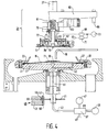
- Figs. 4 to 8 show an arrangement which provides the substrate 5 with the cured replication layer 11.
- the arrangement comprises a mould carrier 17 which carries the mould 15.
- application means in the form of a pivotable spout 19 for applying the replication material 11 in a deformable phase to the mould 15.
- the arrangement further comprises a substrate carrier 21 which is movable relative to the mould 15 and which has holding means 23 and 25 for holding the substrate 5.
- transfer means 27 for transferring the substrate carrier with the substrate to and from the mould.
- the mould carrier 17 comprises a rotating turntable provided with means for securing the mould to the turntable.
- Said means comprise a ring 27 and a plurality of bolts 29 for fastening the ring to the turntable 17.
- the ring 27 presses the mould 15 at its circumference against a rim 31 of the turntable and against an O-ring provided on the turntable.
- the mould 15 has a central opening through which a central cone 35 projects above the mould surface. The significance of this cone will be explained in the subsequent description of the method.
- the replication material 11 is deposited around the cone 35 on the mould 15.
- pneumatic means such as an electrically controlled pneumatic valve 37, a compressed-air source 39, a pneumatic line 41, and an air duct 43 in the turntable 17.
- pneumatic means serve inter alia for bulging up the mould 15 by means of compressed air, see also Figs. 4 and 5.
- an outlet duct 45 which can be connected to the pneumatic line 41 by the pneumatic valve 37.
- the line 41 can also be connected to a vacuum source 47, so that the mould 15 can be drawn tightly against the surface of the turntable 17 by means of vacuum. This is of importance in order to obtain a replication layer of satisfactory flatness.
- the turntable 17 can be set to an initial position which is accurately defined in the direction of rotation.
- the arrangement comprises suitable means 49 and 51.
- the means 49 form an optical unit comprising a frame 53 in which a light source 55 and a light-sensitive cell 57 are arranged in facing relationship at opposite sides of an air gap 59.
- the means 51 comprises a disc which is mounted on the spindle 61 of the turntable 17 and which has a recess 63.
- the disc 51 is fixedly connected to the spindle 61 and its circumference revolves in the air gap 59 of the optical unit 49 . In this way the position of the recess 63 can be detected optically with a satisfactory degree of accuracy.
- the afore-mentioned holding means 23 and 25 of the substrate carrier 21 comprise two series of concentrically arranged suction pads 23 and 25. With the aid of these suction pads and vacuum means 65 to 73 the substrate can be held by the substrate carrier 21 by means of a partial vacuum.
- the pneumatic means comprise the vacuum lines 65 and 67, represented symbolically in broken lines, which are connected to the suction pads 23 and 25.
- the flexible vacuum lines are connected to electrically controlled vacuum valves 69 and 71, which are connected directly to a vacuum source 73.
- the valves 69 and 71 can be controlled independently from one another, so that the suction pads 23 and 25 can be evacuated independently of one another.
- a certain amount of replication material 11 in a deformable phase for example a liquid phase, is deposited on the upper side of the mould 15.
- the substrate 5 is made of glass and therefore it is comparatively stiff and only flexible to a limited extent.
- the mould 15 is brought in a slightly bulged condition, see Fig. 4, by compressed air from the compressed-air source 39 before or after the application of the replication material.
- An alternative method which will not be described any further, employs a more flexible substrate made of a suitable plastics which in a slightly bulged-up condition is mounted onto a flat mould.
- the substrate 5 is held on the substrate carrier 21 by means of the suction pads 23 and 25.
- the substrate carrier comprises an axially movable centring cone 75.
- the centring cone is connected to an axially movable pin 79 which is urged downward by a compression spring 81.
- Mounting the substrate 5 on and removing it from the substrate carrier 21 is effected in a position not shown, at some distance from the position shown.
- the transfer means required for this and for the rest of the method to be described below are of a conventional nature and are not shown in detail in the drawings.
- the spindle 27 forms part of said means.
- the means further include a yoke 83 and a locating member 85. When in the operating position the locating member 85 is made to cooperate with an accurately fitting locating aperture in a stationary part of the arrangement this will ensure a well-defined operating position.
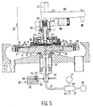
- the substrate carrier 21 together with the substrate 5 is brought from the situation illustrated in Fig. 4 to the situation illustrated in Fig. 5.
- the cone 75 is pressed upward by the cone 35 against the force of the spring 81, so that the cone 35 engages the centre hole 7 in the substrate 5.
- pads 25 release the substrate so that under the influence of gravity and under the influence of the radial forces exerted by the cone 35 the substrate can independently assume a correctly centred position on the mould.
- the substrate carrier is further lowered and the compressed air in the space between the turntable 17 and the substrate 15 is allowed to escape, so that the initially bulged condition of the mould disappears.
- the replication material 11 is gradually and uniformly pressed in a radially outward direction.
- the substrate 5 is fixed to the mould 15 in the centred position. This is effected by locally solidifying a part of the replication layer 11 in an area situated outside the structure zone 3.
- the substrate consists of a transparent glass type and the replication layer 11 consists of a transparent radiation-curable lacquer.
- Fixing the substrate 5 to the mould 15 is effected by solidifying a part of the replication layer situated in an annular zone 87 (Fig. 1) between the structure zone 3 and the edge of the centre hole 7.
- the annular lamp 22 arranged inside the substrate carrier 21 is used. This lamp is situated in the space 26 which is open towards the substrate side.
- the cylindrical shield 77 ensures that the light of the lamp 22 can only emerge through an annular opening.
- the substrate carrier After curing of the fixation zone the substrate carrier is moved away from the mould into the position shown in Fig. 7.
- An exposure and rinsing unit 89 shown only diagrammatically in Fig. 7, is now moved between the substrate carrier and the turntable.
- the turntable 17 is rotated while exposure means, not shown and belonging to the unit 89, expose the residual replication material for the purpose of curing.
- Two ports 91 and 93 are used for applying a solvent which serves for dissolving and rinsing off redundant replication material.
- a blowing nozzle 95 for blowing away excess solvent and replication material at the location of the edge of the centre hole 7 of the substrate.
- the exposure and rinsing unit 89 is moved away out of its position between the substrate carrier and the turntable. Once the turntable has stopped the substrate with the replication layer attached to it can be removed from the mould.
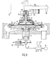
- the suction pads 23 of the substrate carrier are situated on an external flange 97 of a sliding bush 99.
- the sliding bush has an annular stop 101 to ensure that under the influence of gravity the sliding bush cannot be lowered any further than shown in Figs. 7 and 8.
- Removal of the substrate with the attached replication layer from the mould proceeds as follows.
- compressed air from the compressed-air source 39 is admitted underneath the mould 15 the mould is pressed upward, so that the edge of the substrate and then progressively more inward parts of the substrate become detached from the mould.
- the substrate carrier is lowered from its position shown in Fig. 7 into the position shown in Fig. 8.
- By evacuating the suction pads 23 by means of the vacuum source 37 the substrate 5 is drawn against the substrate carrier at its upper side near its circumferential edge, after which the substrate can be moved upward together with the substrate carrier.
- the suction pads 23 will release the substrate, so that the product can be removed. In general, this will be effected in a position at some distance from the turntable 17.
- the drawings show a micromanipulator 103 by means of which the position of the substrate carrier in a direction parallel to the plane of drawing can be adjusted with high accuracy.
- the drawings do not show a second micromanipulator which enables the position of the substrate carrier in a direction transverse to the plane of drawing to be adjusted.
- These two adjustment means enable the position of the substrate carrier to be corrected in two mutually perpendicular positions parallel to the surface of the turntable 17. This correction possibility is of the utmost importance to guarantee that products are manufactured with an eccentricity not exceeding a prescribed permissible eccentricity.
- the procedure required for this must be carried out only once after every mould change. For changing a mould the ring 27 is removed, after which the mould 15 can be replaced by another mould.
- a substrate 5 is placed on the substrate carrier 21 in a manner as described above and a test product is manufactured wholly in conformity with the method described above.
- the finished product is removed from the substrate carrier and by means of suitable measuring instruments, preferably optical measuring instruments, the eccentricity of the optically readable structure of the test product relative to the centre of rotation is measured.
- suitable measuring instruments preferably optical measuring instruments
- the corrections to be applied by means of the manipulators can be derived from the measurement results. After the necessary corrections have been applied subsequent products can be manufactured with the required accuracy of the eccentricity of the optically readable structure without any further corrections being needed.
- the substrate and/or the replication layer need not be transparent and curing need not be effected by means of radiation.
- Non-transparent substrates and replication layers may be used and other methods of chemical or physical hardening are applicable.
- the essence of the invention resides in the fact that a substrate is accurately centred on a mould by means of a substrate carrier, the substrate is secured to said mould in a centred position through local fixation, and the substrate is subsequently released from the substrate carrier to allow the replication layer to be cured in the structure zone without contact with the substrate carrier and preferably while the mould is rotating.
- the substrate can be fixed to the mould in an entirely other manner than described.
- there may be provided movable fixation means which temporarily hold the substrate.
- Another method is the use of a vacuum to hold the substrate temporarily.
Landscapes
- Engineering & Computer Science (AREA)
- Mechanical Engineering (AREA)
- Manufacturing & Machinery (AREA)
- Manufacturing Optical Record Carriers (AREA)
- Casting Or Compression Moulding Of Plastics Or The Like (AREA)
- Moulds For Moulding Plastics Or The Like (AREA)
Claims (18)
- Verfahren zum Herstellen einer optisch auslesbaren Platte (1) durch Bildung einer optisch auslesbaren Struktur (9) in einer Strukturzone (3) auf einem Träger (5), wobei dieses Verfahren die nachfolgenden Verfahrensschritte umfaßt: das Anbringen einer Replikationsschicht (11) in einer verformbaren Phase auf einer Matrize (15) mit einer Matrizenstruktur (13), das Auflegen des Trägers auf die Replikationsschicht und das Verbinden derselben mit dem Träger, das Entfernen der resultierenden Verbindung, bestehend aus dem Träger und der daran befestigten Replikationsschicht aus der Matrize,
gekennzeichnet durch die nachfolgenden Verfahrensschritte:- das Anbringen des Trägers (5) auf einem beweglichen Trägerhalter (21),- das Verlagern des Trägerhalters derart, daß der Träger in eine zentrierte Lage - auf der Replikationsschicht (11) auf der Matrize (15) angebracht wird,- das Befestigen des Trägers (5) an der Matrize (15) in der zentrierten Lage,- das Lösen des Trägers von dem Trägerhalter nach der Befestigung, und- das Erstarren der Replikationsschicht in der Strukturzone (3) in der befestigten Lage. - Verfahren nach Anspruch 1, dadurch gekennzeichnet, daß der Träger (5) durch örtliche Erstarrung der Replikationsschicht (11) in einem Bereich außerhalb der Strukturzone an der Matrize (15) befestigt ist.
- Verfahren nach Anspruch 1, dadurch gekennzeichnet, daß der träger (5) transparent ist und die Replikationsschicht (11) aus einem strahlungshärtbaren Lack besteht, und daß die Fixierung des Trägers (5) an der Matrize (15) sowie die Erstarrung der Replikationsschicht in der Strukturzone (3) durch Strahlung durch den Träger hindurch erfolgt.
- Verfahren nach Anspruch 3, dadurch gekennzeichnet, daß der Trägerhakter (21) einen strahlungsdurchlässigen Teil (26) aufweist und der Träger durch Strahlung durch den genannten strahlungsdurchlässigen Teil hindurch an der Matrize befestigt wird.
- Verfahren nach Anspruch 4, dadurch gekennzeichnet, daß Fixierung in einer kreisförmigen oder ringförmigen Fixierungszone (87) erfolgt.
- Verfahren nach Anspruch 1, dadurch gekennzeichnet, daß zum Erhalten von Platten, deren Exzentrizität inerhalb enger Toleranzen liegt, in einer Testphase des Verfahrens ein Testerzeugnis hergestellt wird, indem das Verfahren durchgeführt wird, wobei ein Träger verwendet wird, der ungefähr in dem Trägerhalter zentriert ist, daß die Exzentrizität der optisch auslesbaren Struktur des Testerzeugnisses gegenüber der Rotationsmitte ermittelt wird, und daß die Lage des Trägerhalters je nach dem Wert der auf diese Weise ermittelten Exzentrizität korrigiert wird.
- Verfahren nach Anspruch 6, dadurch gekennzeichnet, daß beim Aushärten der Replikationsschicht (11) die Matrize (5) gedreht wird und daß bevor ein Träger (5) angeordnet wird, die Matrize in eine Ausgangslage gebracht wird, die in der Drehrichtung genau definiert ist.
- Verfahren nach Anspruch 1, dadurch gekennzeichnet, daß die Matrize einen größeren Durchmesser hat als der Träger und der Träger über die ganze Oberfläche mit einer Replikationsschicht bedeckt ist.
- Verfahren nach Anspruch 1, dadurch gekennzeichnet, daß der Träger mit der anhaftenden Replikationsschicht durch Aufbauschung der Matrize von dem Trägerhalter entfernt wird.
- Verfahren nach Anspruch 1, dadurch gekennzeichnet, daß bevor der Träger auf der Matrize angebracht wird, diese Matrize in eine Aufbauschform gebracht und der Träger in die Replikationsschicht hineingepreßt wird, während gleichzeitig die Aufbauschung der Matrize verringert wird.
- Einrichtung zum Herstellen einer optisch auslesbaren Platte (1) durch Bildung einer optisch auslesbaren Struktur (9) in einer Strukturzone (3) auf einem Träger (5), wobei diese Einrichtung einen Matrizenträger (17) für eine zu unterstützende Matrize (15) aufweist, sowie Zuführungsmittel (19) zum Zufuhren von Replikationsmaterial (11) in einer verformbaren Phase zu der Matrize, dadurch gekennzeichnet, daß die Einrichtung sie einen Trägerhalter (21) aufweist, der gegenüber der Matrize (15) verlagerbar ist und Haltemittel (23, 25) aufweist zum Haltern eines Trägers (5) und Übertragungsmittel (27) zum Übertragen des Trägerhalters (21) zusammen mit dem Träger (5) zu und von der Matrize (15).
- Einrichtung nach Anspruch 11, dadurch gekennzeichnet, daß der Matrizenhalter einen Drehtisch (17) mit Mitteln zum Befestigen der Matrize an dem Tisch aufweist.
- Einrichtung nach Anspruch 12, dadurch gekennzeichnet, daß die Matrize (15) eine zentrale Öffnung aufweist, durch die ein zentraler Kegel (35) über die Matrizenoberfläche hinausragt.
- Einrichtung nach Anspruch 11, dadurch gekennzeichnet, daß pneumatische Mittel (3743) vorgesehen sind zum Aufbauschen der Matrize (15) durch Druckluft.
- Einrichtung nach Anspruch 12 oder 13, dadurch gekennzeichnet, daß sie Mittel (49, 51) aufweist um den Drehtisch auf genau reproduzierbare Weise in die Ausgangslage zu bringen.
- Einrichtung nach Anspruch 11, dadurch gekennzeichnet, daß Vakuummittel (65-73) vorgesehen sind zum Festhalten des Trägers (5) auf dem Trägerhalter (21) durch ein Partialvakuum.
- Einrichtung nach Anspruch 11, dadurch gekennzeichnet, daß der verlagerbare Trägerhalter (21) eine innere Strahlungsquelle (22) aufweist zur,zentralen Fixierung des Trägers an der Matrize.
- Einrichtung nach Anspruch 17, dadurch gekennzeichnet, daß der Trägerhalter Schutzmittel (77) aufweist zur Vermeidung einer Fixierung außerhalb der zentralen Zone.
Applications Claiming Priority (2)
| Application Number | Priority Date | Filing Date | Title |
|---|---|---|---|
| NL9002517A NL9002517A (nl) | 1990-11-19 | 1990-11-19 | Werkwijze voor het vervaardigen van een optisch uitleesbare plaat, alsmede inrichting voor de uitvoering van de werkwijze. |
| NL9002517 | 1990-11-19 |
Publications (3)
| Publication Number | Publication Date |
|---|---|
| EP0487138A2 EP0487138A2 (de) | 1992-05-27 |
| EP0487138A3 EP0487138A3 (en) | 1992-12-09 |
| EP0487138B1 true EP0487138B1 (de) | 1997-02-05 |
Family
ID=19857997
Family Applications (1)
| Application Number | Title | Priority Date | Filing Date |
|---|---|---|---|
| EP91202927A Expired - Lifetime EP0487138B1 (de) | 1990-11-19 | 1991-11-12 | Verfahren zum Herstellen einer optisch auslesbaren Platte, sowie Einrichtung zum Durchführen des Verfahrens |
Country Status (7)
| Country | Link |
|---|---|
| US (2) | US5242629A (de) |
| EP (1) | EP0487138B1 (de) |
| JP (1) | JPH04268224A (de) |
| KR (1) | KR920010555A (de) |
| DE (1) | DE69124575T2 (de) |
| ES (1) | ES2099733T3 (de) |
| NL (1) | NL9002517A (de) |
Families Citing this family (11)
| Publication number | Priority date | Publication date | Assignee | Title |
|---|---|---|---|---|
| CA2150314A1 (en) * | 1994-07-26 | 1996-01-27 | Daniel Schichman | Replicated relay lens system |
| US5804017A (en) * | 1995-07-27 | 1998-09-08 | Imation Corp. | Method and apparatus for making an optical information record |
| NL1005663C2 (nl) * | 1997-01-31 | 1998-08-03 | Ict Axxicon Bv | Inrichting voor het door spuitgieten vervaardigen van informatie-dragers. |
| NL1005937C2 (nl) * | 1997-04-29 | 1998-11-02 | Ict Axxicon Bv | Inrichting voor het door spuitgieten vervaardigen van informatie-dragers. |
| EP1030814B1 (de) * | 1997-11-12 | 2003-03-26 | STEAG HamaTech, Inc. | System und verfahren zum beibehalten der zentrierung eines oberen und unteren substrats während des verbindens einer verbunddatenspeicherplatte |
| US6098272A (en) * | 1998-05-19 | 2000-08-08 | First Light Technology, Inc. | System for maintaining concentricity of a combination of a top and bottom substrate during the assembly of a bonded storage disk |
| US7717696B2 (en) * | 2000-07-18 | 2010-05-18 | Nanonex Corp. | Apparatus for double-sided imprint lithography |
| US6692246B1 (en) * | 2000-10-31 | 2004-02-17 | Valdas Ltd. (A British Virgin Island Corp.) | Apparatus for uninterrupted multi-layer disc manufacturing |
| JP3630644B2 (ja) * | 2001-05-17 | 2005-03-16 | 株式会社ソニー・ディスクテクノロジー | 物体運搬装置 |
| JP4118083B2 (ja) * | 2002-05-09 | 2008-07-16 | Tdk株式会社 | スタンパ貼合せ方法および装置 |
| CN112397099B (zh) * | 2020-12-01 | 2022-04-15 | 北京中科开迪软件有限公司 | 一种用于光盘生产线的精准定位设备 |
Family Cites Families (21)
| Publication number | Priority date | Publication date | Assignee | Title |
|---|---|---|---|---|
| US3303537A (en) * | 1964-04-07 | 1967-02-14 | Systems Matrix Inc | Safety ejection control for casting machines |
| NL177721B (nl) * | 1977-03-14 | 1985-06-03 | Philips Nv | Werkwijze voor het vervaardigen van een kunststofinformatiedrager met gelaagde structuur alsmede een inrichting voor het uitvoeren van de werkwijze. |
| FR2397931A1 (fr) * | 1977-07-22 | 1979-02-16 | Thomson Brandt | Procede de reproduction de disque support d'information et disque obtenu par un tel procede |
| FR2445761A1 (fr) * | 1979-01-04 | 1980-08-01 | Thomson Brandt | Procede de fabrication de disques souples et dispositif destine a la mise en oeuvre de ce procede |
| NL7906117A (nl) * | 1979-08-10 | 1981-02-12 | Philips Nv | Werkwijze en inrichting voor het vervaardigen van een kunststofinformatiedrager. |
| FR2468456A1 (fr) * | 1979-09-06 | 1981-05-08 | Thomson Csf | Dispositif de moulage de disques porteurs d'informations |
| EP0047645B1 (de) * | 1980-09-05 | 1984-11-28 | Matsushita Electric Industrial Co., Ltd. | Verfahren zum Herstellen einer Datenträgerplatte |
| US4449916A (en) * | 1980-11-20 | 1984-05-22 | Matsushita Electric Industrial Co., Ltd. | Device for manufacturing information recording mediums |
| JPS57163533A (en) * | 1981-04-01 | 1982-10-07 | Toppan Printing Co Ltd | Preparation of information recording carrier |
| FR2516286A1 (fr) * | 1981-11-06 | 1983-05-13 | Thomson Csf | Procede d'obtention d'un disque-copie a partir d'une gravure originale portee par une matrice |
| NL8200634A (nl) * | 1982-02-18 | 1983-09-16 | Philips Nv | Werkwijze en inrichting voor het vormen van een doorzichtig voorwerp. |
| JPS60122140A (ja) * | 1983-12-06 | 1985-06-29 | Pioneer Electronic Corp | 情報記録円板の製造装置 |
| JPS60122139A (ja) * | 1983-12-06 | 1985-06-29 | Pioneer Electronic Corp | 情報記録円板の製造装置 |
| GB2155388A (en) * | 1984-03-09 | 1985-09-25 | Philips Electronic Associated | Moulding an accurately centred lens surface |
| NL8501148A (nl) * | 1985-04-19 | 1986-11-17 | Optical Storage Int | Werkwijze voor het aanbrengen van een optisch detecteerbare structuur op het substraat van een optisch uitleesbare informatieschijf, matrijs ten behoeve van de werkwijze, inrichting voor het uitvoeren van de werkwijze, alsmede informatieschijf vervaardigd volgens de werkwijze. |
| JPS61252497A (ja) * | 1985-04-22 | 1986-11-10 | Seibu Giken:Kk | 湿気交換用または全熱交換用の吸着型素子の製造法 |
| JP2515757B2 (ja) * | 1986-10-13 | 1996-07-10 | パイオニア株式会社 | 光学式情報記録円盤の製造方法 |
| JPH0626823B2 (ja) * | 1987-10-15 | 1994-04-13 | パイオニア株式会社 | 光ディスク製造装置 |
| US4907956A (en) * | 1988-04-27 | 1990-03-13 | Dainippon Ink And Chemicals, Inc. | Apparatus for manufacturing optical information recording medium |
| JPH01291926A (ja) * | 1988-05-19 | 1989-11-24 | Nec Corp | ディスク成形装置 |
| JP2636903B2 (ja) * | 1988-09-30 | 1997-08-06 | 株式会社リコー | 光ディスク基板の射出成形用金型 |
-
1990
- 1990-11-19 NL NL9002517A patent/NL9002517A/nl not_active Application Discontinuation
-
1991
- 1991-11-12 DE DE69124575T patent/DE69124575T2/de not_active Expired - Fee Related
- 1991-11-12 EP EP91202927A patent/EP0487138B1/de not_active Expired - Lifetime
- 1991-11-12 ES ES91202927T patent/ES2099733T3/es not_active Expired - Lifetime
- 1991-11-15 KR KR1019910020345A patent/KR920010555A/ko not_active Abandoned
- 1991-11-18 US US07/795,167 patent/US5242629A/en not_active Expired - Fee Related
- 1991-11-18 JP JP3301827A patent/JPH04268224A/ja active Pending
-
1995
- 1995-10-10 US US08/542,000 patent/US5626885A/en not_active Expired - Fee Related
Also Published As
| Publication number | Publication date |
|---|---|
| DE69124575T2 (de) | 1997-07-24 |
| US5626885A (en) | 1997-05-06 |
| EP0487138A3 (en) | 1992-12-09 |
| DE69124575D1 (de) | 1997-03-20 |
| JPH04268224A (ja) | 1992-09-24 |
| NL9002517A (nl) | 1992-06-16 |
| KR920010555A (ko) | 1992-06-26 |
| US5242629A (en) | 1993-09-07 |
| ES2099733T3 (es) | 1997-06-01 |
| EP0487138A2 (de) | 1992-05-27 |
Similar Documents
| Publication | Publication Date | Title |
|---|---|---|
| US5626885A (en) | Method of manufacturing an optically readable disc, and arrangement for carrying out the method | |
| EP0833315B1 (de) | Verfahren zum Korrigieren von der ungleichen Position einer Informationsscheibe | |
| WO1982004119A1 (en) | Improved optical disc unit,and cooperating record/playback apparatus | |
| US4911776A (en) | Method of manufacturing a mold for an optically readable information disc | |
| EP1489609B1 (de) | Herstellungsverfahren für ein mehrschichtiges optisches informationsaufzeichnungsmedium | |
| JP2941196B2 (ja) | 光ディスクの製造方法および製造装置 | |
| JPH04370548A (ja) | 光記録ディスク用基体の製造方法およびそれを実施するための装置 | |
| US5579113A (en) | Apparatus for testing matrixes | |
| EP0067095B1 (de) | Verfahren zur Herstellung steifer optischer Scheiben | |
| WO2004001738A1 (ja) | 円板状基板用成膜装置に対する基板の受け渡し方法、当該方法に用いられる基板受け渡し機構および基板ホルダ、および当該方法を用いたディスク状記録媒体の製造方法 | |
| WO2003085659A1 (en) | Method of delivering substrates to a film forming device for disk-like substrates, substrate delivering mechanism and mask used in such method, and disk-like recording medium producing method using such method | |
| JPH03141052A (ja) | 光学的記録担体の複製方法および複製装置 | |
| EP1810292B1 (de) | Neigungsverwaltungseinrichtung und -verfahren | |
| JPH09167385A (ja) | 2p成形装置 | |
| US6084236A (en) | System for mounting a hubless glassmaster onto an orders measurement device | |
| JP3676936B2 (ja) | マスタースタンパへの裏打ち板接合装置 | |
| JP2533182B2 (ja) | 光ディスクの製造方法 | |
| JPH01211342A (ja) | 光学式ディスクの製造法 | |
| JP3812832B2 (ja) | ディスク基板受台 | |
| JPH10154360A (ja) | ディスク貼合わせ装置 | |
| JPH03280229A (ja) | 光ディスク基板作製装置 | |
| JPH0741191B2 (ja) | 回転塗布装置 | |
| JPH02286309A (ja) | 光ディスク複製装置 | |
| JPH0589529A (ja) | 光デイスクの製造方法 | |
| JPH0596918U (ja) | ディスク・クランプエリア部コート液付着検査装置 |
Legal Events
| Date | Code | Title | Description |
|---|---|---|---|
| PUAI | Public reference made under article 153(3) epc to a published international application that has entered the european phase |
Free format text: ORIGINAL CODE: 0009012 |
|
| AK | Designated contracting states |
Kind code of ref document: A2 Designated state(s): DE ES FR GB IT |
|
| PUAL | Search report despatched |
Free format text: ORIGINAL CODE: 0009013 |
|
| AK | Designated contracting states |
Kind code of ref document: A3 Designated state(s): DE ES FR GB IT |
|
| 17P | Request for examination filed |
Effective date: 19930526 |
|
| 17Q | First examination report despatched |
Effective date: 19950410 |
|
| GRAG | Despatch of communication of intention to grant |
Free format text: ORIGINAL CODE: EPIDOS AGRA |
|
| GRAH | Despatch of communication of intention to grant a patent |
Free format text: ORIGINAL CODE: EPIDOS IGRA |
|
| GRAH | Despatch of communication of intention to grant a patent |
Free format text: ORIGINAL CODE: EPIDOS IGRA |
|
| GRAA | (expected) grant |
Free format text: ORIGINAL CODE: 0009210 |
|
| AK | Designated contracting states |
Kind code of ref document: B1 Designated state(s): DE ES FR GB IT |
|
| REF | Corresponds to: |
Ref document number: 69124575 Country of ref document: DE Date of ref document: 19970320 |
|
| ITF | It: translation for a ep patent filed | ||
| ET | Fr: translation filed | ||
| REG | Reference to a national code |
Ref country code: ES Ref legal event code: FG2A Ref document number: 2099733 Country of ref document: ES Kind code of ref document: T3 |
|
| PGFP | Annual fee paid to national office [announced via postgrant information from national office to epo] |
Ref country code: GB Payment date: 19971103 Year of fee payment: 7 |
|
| PGFP | Annual fee paid to national office [announced via postgrant information from national office to epo] |
Ref country code: FR Payment date: 19971118 Year of fee payment: 7 |
|
| PGFP | Annual fee paid to national office [announced via postgrant information from national office to epo] |
Ref country code: ES Payment date: 19971121 Year of fee payment: 7 |
|
| PLBE | No opposition filed within time limit |
Free format text: ORIGINAL CODE: 0009261 |
|
| STAA | Information on the status of an ep patent application or granted ep patent |
Free format text: STATUS: NO OPPOSITION FILED WITHIN TIME LIMIT |
|
| PGFP | Annual fee paid to national office [announced via postgrant information from national office to epo] |
Ref country code: DE Payment date: 19980123 Year of fee payment: 7 |
|
| 26N | No opposition filed | ||
| REG | Reference to a national code |
Ref country code: FR Ref legal event code: CD |
|
| PG25 | Lapsed in a contracting state [announced via postgrant information from national office to epo] |
Ref country code: GB Free format text: LAPSE BECAUSE OF NON-PAYMENT OF DUE FEES Effective date: 19981112 |
|
| PG25 | Lapsed in a contracting state [announced via postgrant information from national office to epo] |
Ref country code: ES Free format text: LAPSE BECAUSE OF NON-PAYMENT OF DUE FEES Effective date: 19981113 |
|
| REG | Reference to a national code |
Ref country code: ES Ref legal event code: PC2A |
|
| GBPC | Gb: european patent ceased through non-payment of renewal fee |
Effective date: 19981112 |
|
| PG25 | Lapsed in a contracting state [announced via postgrant information from national office to epo] |
Ref country code: FR Free format text: LAPSE BECAUSE OF NON-PAYMENT OF DUE FEES Effective date: 19990730 |
|
| REG | Reference to a national code |
Ref country code: FR Ref legal event code: ST |
|
| PG25 | Lapsed in a contracting state [announced via postgrant information from national office to epo] |
Ref country code: DE Free format text: LAPSE BECAUSE OF NON-PAYMENT OF DUE FEES Effective date: 19990901 |
|
| REG | Reference to a national code |
Ref country code: ES Ref legal event code: FD2A Effective date: 19991214 |
|
| PG25 | Lapsed in a contracting state [announced via postgrant information from national office to epo] |
Ref country code: IT Free format text: LAPSE BECAUSE OF NON-PAYMENT OF DUE FEES Effective date: 20051112 |