EP0484900B1 - Verfahren und Vorrichtung zum Ändern der Farbdichte für einen Drucker - Google Patents
Verfahren und Vorrichtung zum Ändern der Farbdichte für einen Drucker Download PDFInfo
- Publication number
- EP0484900B1 EP0484900B1 EP91118901A EP91118901A EP0484900B1 EP 0484900 B1 EP0484900 B1 EP 0484900B1 EP 91118901 A EP91118901 A EP 91118901A EP 91118901 A EP91118901 A EP 91118901A EP 0484900 B1 EP0484900 B1 EP 0484900B1
- Authority
- EP
- European Patent Office
- Prior art keywords
- density
- data
- host computer
- printer
- image data
- Prior art date
- Legal status (The legal status is an assumption and is not a legal conclusion. Google has not performed a legal analysis and makes no representation as to the accuracy of the status listed.)
- Expired - Lifetime
Links
- 238000000034 method Methods 0.000 title description 5
- 230000003287 optical effect Effects 0.000 claims description 5
- 230000004044 response Effects 0.000 claims description 2
- 230000001105 regulatory effect Effects 0.000 description 13
- 239000003086 colorant Substances 0.000 description 9
- 238000010586 diagram Methods 0.000 description 5
- 238000001514 detection method Methods 0.000 description 2
- 238000006243 chemical reaction Methods 0.000 description 1
- 238000004040 coloring Methods 0.000 description 1
- 230000003247 decreasing effect Effects 0.000 description 1
- 230000000694 effects Effects 0.000 description 1
- 230000000087 stabilizing effect Effects 0.000 description 1
- 238000000859 sublimation Methods 0.000 description 1
- 230000008022 sublimation Effects 0.000 description 1
Images


Classifications
-
- H—ELECTRICITY
- H04—ELECTRIC COMMUNICATION TECHNIQUE
- H04N—PICTORIAL COMMUNICATION, e.g. TELEVISION
- H04N1/00—Scanning, transmission or reproduction of documents or the like, e.g. facsimile transmission; Details thereof
- H04N1/40—Picture signal circuits
- H04N1/407—Control or modification of tonal gradation or of extreme levels, e.g. background level
- H04N1/4072—Control or modification of tonal gradation or of extreme levels, e.g. background level dependent on the contents of the original
-
- B—PERFORMING OPERATIONS; TRANSPORTING
- B41—PRINTING; LINING MACHINES; TYPEWRITERS; STAMPS
- B41J—TYPEWRITERS; SELECTIVE PRINTING MECHANISMS, i.e. MECHANISMS PRINTING OTHERWISE THAN FROM A FORME; CORRECTION OF TYPOGRAPHICAL ERRORS
- B41J2/00—Typewriters or selective printing mechanisms characterised by the printing or marking process for which they are designed
- B41J2/52—Arrangement for printing a discrete number of tones, not covered by group B41J2/205, e.g. applicable to two or more kinds of printing or marking process
-
- B—PERFORMING OPERATIONS; TRANSPORTING
- B41—PRINTING; LINING MACHINES; TYPEWRITERS; STAMPS
- B41J—TYPEWRITERS; SELECTIVE PRINTING MECHANISMS, i.e. MECHANISMS PRINTING OTHERWISE THAN FROM A FORME; CORRECTION OF TYPOGRAPHICAL ERRORS
- B41J2/00—Typewriters or selective printing mechanisms characterised by the printing or marking process for which they are designed
- B41J2/525—Arrangement for multi-colour printing, not covered by group B41J2/21, e.g. applicable to two or more kinds of printing or marking process
Definitions
- the present invention relates to a printer for printing data inputted from a host computer.
- FIG. 11 shows, in block form, a typical example of a conventional printer together with a host computer connected to the printer.
- the printer 2 comprises an operation panel 3 for regulating density of respective colors of a print, a CPU 4 connected to the operation panel 3, a data input circuit 5 connected to the external host computer 1 such as personal computer to receive an image information therefrom, an image memory 6 connected to the input circuit 5 to store the image information, a fixed density regulator circuit 7 connected to the CPU 4 and the image memory 6 and constituted with, for example, a ROM , to regulate the image information read out from the image memory 6 according to color regulation information supplied from the operation panel 3 through the CPU 4, a thermal head drive circuit 8 connected to the fixed density regulator circuit 7 and a thermal head 9 connected to the thermal head drive circuit 8.
- ink sheet and/or printer to be used to print image data supplied by the host computer 1 varies printer by printer, it is necessary, in order to obtain a satisfactory print by using any available printer and ink sheet, that colors Y (yellow), M (magenta), C (cyan) and BK (black) of the print are regulated in density correspondingly to the printer and ink sheet used.
- the user looks at the resultant print and regulates densities of respective colors through the operation panel 3 if the print is not satisfactory, and this procedure is repeated until a fully satisfactory print is obtained.
- a printing density controller for enabling constant colouring density is known.
- a specific test pattern is printed each time thermo-sensible paper is exchanged.
- the controller includes a density sensor supplying a detection signal to an A/D converter for converting the detection signal into a digital signal.
- the digital signal is supplied to a pulse width setting circuit.
- a printing density regulator for stabilizing the printing density.
- Printing densities are classified into a plurality of levels, and a plurality of resistors corresponding to a required printing density are provided. According to the required density level, anyone of the resistors is selected with a switch.
- An object of the present invention is to provide a printer capable of automatically and efficiently regulating color density.
- this object is solved by a printer for printing data inputted from a host computer, said data including image data and commands instructing a change of density of at least one colour to be printed; the printer comprising
- the density of the input data is regulated by the first density regulating means according to the first operation.
- the density of the output of the first density regulating means is regulated by the second density regulating means according to the second operation and the output of the second density regulating means is printed.
- a printer of sublimation type factors such as color density determing factors, etc., which are necessary to obtain a constant print quality regardless of variation of ink sheet and/or variation of printer to be used, can be set arbitrarily by sending a command by an operator through a host computer.
- Fig. 1 is a block diagram of an embodiment of the printer according to the present invention.
- a printer 2A is connected to a host computer 1.
- the printer 2A in this embodiment includes, in addition to an operation panel 3, a CPU 4, a data input circuit 5, an image memory 6, a fixed density regulator circuit 7, a thermal head drive circuit 8 and a thermal head 9 connected to the thermal head drive circuit 8 shown in Fig.
- a command input circuit 10 having an input connected to the host computer 1 and an output connected to a CPU 4, a variable density regulator circuit 12 composed of EEPROM, etc., a change-over switch 11 for selectively connecting an input of the variable density regulator circuit 12 to the host computer 1 or to the CPU 4, a second change-over switch 13 for selectively connecting an input of the data input circuit 5 to an output of the variable density regulator circuit 12 or connecting the variable density regulator 12 to the CPU 4.
- the command input circuit 10, the CPU 4, the switch circuits 11 and 13 and the variable density regulator circuit 12 constitute first density regulator means and the command input circuit 10, the operation panel 3, the CPU 4 and the fixed density regulator circuit 7 constitute second density regulator means.
- the thermal head drive circuit 8 and the thermal head 9 constitute output means.
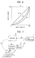
- Fig. 2 is a block diagram showing the switch circuits 11 and 13 and the variable density regulator circuit 12 in more detail and Fig. 3 shows a density characteristics of the variable density regulator circuit 12, in which input density and output density are plotted along abscissa and ordinate, respectively, scaled from 0 to 255 to cover 256 levels each represented by 8 bits. The larger the value indicates the higher the density.
- a curve SC is a standard curve and a curve CC is a correction curve.
- the switches 11 and 13 are in the positions shown in Fig. 1 and image data from the host computer 1 is loaded in the variable density regulator circuit 12, corrected according to the standard curve SC and supplied through the switch 13 to the data input circuit 5. Subsequent operation to this is the same as that of the conventional printer.
- the CPU 4 responds to the command C1 sent through the command input circuit 10 to actuate the switch circuits 11 and 13 to the state shown in Fig. 2 so that the correction data is supplied to the variable density regulator circuit 12.
- the density characteristics of the variable density regulator circuit 12 becomes that shown by the correction curve CC in Fig. 3. Therefore, it becomes possible to arbitrarily regulate density by the user through the host computer 1. Thus, the first density regulation is performed.
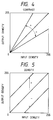
- Figs. 4 to 6 show density characteristics of the fixed density regulator circuit 7 with abscissa and ordinate showing output density in 256 (0 to 255) levels, for contrast parameter A, density parameter B and gamma parameter, respectively.
- the CPU 4 causes the fixed density regulator circuit 7 which has been loaded with a plurality of data including different values of respective parameters A, B and ⁇ to select a density charateristics of different contrast such as shown in Fig. 4. For example, when the parameter A has a large value, the contrast becomes large and vice versa.
- the CPU 4 causes the fixed density regulator circuit 7 to select the density characteristics of different density such as shown in Fig. 5. The larger the value of the parameter B results in the larger the density and vice versa.
- the user can regulate the density of print by sending any command through the host computer 1.
- Fig. 7 illustrates the procedure for the first density regulation which includes steps 1 to 5
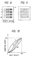
- Fig. 8 shows a standard optical density (OD) pallet 14 showing patterns of colors Y, M, C and BK each printed with different densities
- Fig. 9 shows a pattern of measuring points on a print sheet for measuring density
- Fig. 10 shows a characteristics indicating a correction density data to be loaded in the variable density regulator circuit 12.
- the host computer 1 has held density data read out by an OD meter 15 which may be replaced by a scanner at the respective measuring points on the standard OD pallet 14.
- the printer 2A prints a test pattern on the basis of the density data on the standard OD pallet 14.
- the density of the printed test pattern is read out at the measuring points shown in Fig. 9 by the OD meter 15.
- the density data of the respective measuring points on the test pattern thus read out is sent to the host computer 1.
- the host computer 1 compares the density data of the standard OD pallet 14 with the density data of the test pattern on which it calculates correction ⁇ curves for the respective colors as shown in Fig. 10 by, for example, increasing or decreasing the density data of the standard OD pallet 14 so that the comparison indicates an equality. Further, the host computer 1 indicates subsequent steps to be employed on a display such as CRT.
- step 5 the user looks at the comparison result displayed on the display device, inputs the command C1 through the host computer 1 to instruct the printer 2A to load the correction data to the variable density regulator circuit 12.
- the host computer 1 sends to the variable density regulator circuit 12 data of the correction ⁇ curves for the respective colors to update the content of the variable density regulator circuit 12.
- the second density regulation may be used in a case where a user wishes to change color or colors arbitrarily.
- the user looks at the print and sends through the host computer 1 the command C2, C3 or C4 or any combination of them to the printer 2A to perform a further density regulation of at least one color by means of the fixed density regulator circuit 7.
- the present invention comprises the variable density regulator circuit 12 which can regulate density of a print totally and the fixed density regulator circuit 7 which can regulate a portion of the print finely and the settings of the ⁇ curves and density determining factors of respective colors can be done by the commands from the host computer 1, the density regulation can be done automatically and efficiently.
- the fixed density regulator circuit 7 is set by the commands from the host computer 1, it is possible to perform the same through the operation panel 3 of the printer 2A with the same effect.
Landscapes
- Engineering & Computer Science (AREA)
- Multimedia (AREA)
- Signal Processing (AREA)
- Electronic Switches (AREA)
- Color, Gradation (AREA)
- Facsimile Image Signal Circuits (AREA)
Claims (2)
- Drucker zum Drucken von von einem Hostcomputer (1) eingegebenen Daten, wobei die Daten Bilddaten und Befehle einschließen, welche eine Dichteänderung wenigstens einer zu druckenden Farbe anweisen; wobei der Drucker umfaßt:- eine zentrale Verarbeitungseinheit (4), welche die Befehle über einen Befehlseingabeschaltkreis (10) empfängt;- einen Einsteller (12) für variable Dichte, welcher von dem Hostcomputer (1) während eines gewöhnlichen Druckvorganges Bilddaten empfängt, die Bilddaten korrigiert und die korrigierten Bilddaten an einen Bildspeicher (6) liefert;- eine Meßeinrichtung (15) für optische Dichte zum Auslesen der Dichte eines gedruckten Testmusters;- wobei der Hostcomputer (1) die gelesene Dichte mit Dichtedaten auf einer Standard-Palette (14) optischer Dichte vergleicht und in den Einstellschaltkreis (12) für variable Dichte zu ladende Korrekturdaten berechnet; und- einen Einstellschaltkreis (7) für feste Dichte, welcher Bilddaten von dem Einsteller (12) für variable Dichte empfängt und Bilddaten an eine Thermokopf-Treibereinheit (8) ausgibt, an welchen Daten eine weitere Dichteeinstellung von wenigstens einer zu druckenden Farbe unter Steuerung der zentralen Verarbeitungseinheit (4) auf einen empfangenen Befehl hin durchgeführt worden ist.
- Drucker nach Anspruch 1, gekennzeichnet durch Schalteinrichtungen (11, 13), welche auf einen Befehl von dem Hostcomputer (1) ansprechen, um zu bewirken, daß der Einsteller (12) für variable Dichte die Korrekturdaten lädt.
Applications Claiming Priority (2)
| Application Number | Priority Date | Filing Date | Title |
|---|---|---|---|
| JP302781/90 | 1990-11-09 | ||
| JP2302781A JPH085206B2 (ja) | 1990-11-09 | 1990-11-09 | プリンタ |
Publications (2)
| Publication Number | Publication Date |
|---|---|
| EP0484900A1 EP0484900A1 (de) | 1992-05-13 |
| EP0484900B1 true EP0484900B1 (de) | 1995-02-15 |
Family
ID=17913043
Family Applications (1)
| Application Number | Title | Priority Date | Filing Date |
|---|---|---|---|
| EP91118901A Expired - Lifetime EP0484900B1 (de) | 1990-11-09 | 1991-11-06 | Verfahren und Vorrichtung zum Ändern der Farbdichte für einen Drucker |
Country Status (5)
| Country | Link |
|---|---|
| US (1) | US5189440A (de) |
| EP (1) | EP0484900B1 (de) |
| JP (1) | JPH085206B2 (de) |
| CA (1) | CA2054057A1 (de) |
| DE (1) | DE69107408T2 (de) |
Families Citing this family (10)
| Publication number | Priority date | Publication date | Assignee | Title |
|---|---|---|---|---|
| US5237425A (en) * | 1991-09-06 | 1993-08-17 | Xerox Corporation | Ink compiler for a two color printer |
| JP3083207B2 (ja) * | 1992-07-13 | 2000-09-04 | 京セラミタ株式会社 | 画像形成装置 |
| JP3703162B2 (ja) * | 1994-04-22 | 2005-10-05 | キヤノン株式会社 | 画像形成装置 |
| FR2727816A1 (fr) * | 1994-12-02 | 1996-06-07 | Fast France Adv Sys Tech Sarl | Scanner de tout type de document et procede de mise en oeuvre dudit scanner |
| JP3559633B2 (ja) * | 1995-12-05 | 2004-09-02 | キヤノン株式会社 | 記録装置およびインクジェット記録方法 |
| US5765481A (en) * | 1997-03-11 | 1998-06-16 | Gerber Scientific Products, Inc. | Apparatus and method for working on a length of web material |
| JP3674248B2 (ja) * | 1997-07-01 | 2005-07-20 | ブラザー工業株式会社 | インク噴射装置の駆動装置 |
| JP2007130867A (ja) * | 2005-11-10 | 2007-05-31 | Shinko Electric Co Ltd | プリンタ、および該プリンタにおけるトーンカーブ設定方法 |
| JP5228280B2 (ja) * | 2006-02-13 | 2013-07-03 | 船井電機株式会社 | 印画品質の確認方法 |
| JP2009078482A (ja) * | 2007-09-27 | 2009-04-16 | Nidec Copal Corp | 熱転写型プリンタの自動色補正方法および熱転写型プリンタ |
Family Cites Families (19)
| Publication number | Priority date | Publication date | Assignee | Title |
|---|---|---|---|---|
| JPS55116338A (en) * | 1979-02-28 | 1980-09-06 | Fuji Photo Film Co Ltd | Method and device for processing gradation of xxray picture of breast |
| JPS56141673A (en) * | 1980-04-04 | 1981-11-05 | Matsushita Giken Kk | Picture recording equipment |
| JPS6078449A (ja) * | 1983-10-04 | 1985-05-04 | Dainippon Printing Co Ltd | ビデオ画像の製版装置 |
| US4795281A (en) * | 1984-11-30 | 1989-01-03 | Tohoku Ricoh Co., Ltd. | Self-correcting printer-verifier |
| JPS61206674A (ja) * | 1985-03-12 | 1986-09-12 | Yokogawa Electric Corp | 多色熱転写プリンタ |
| JPH0797852B2 (ja) * | 1985-10-24 | 1995-10-18 | 株式会社日立製作所 | ビデオプリンタ |
| JPS6382762A (ja) * | 1986-09-26 | 1988-04-13 | Ricoh Co Ltd | 印字濃度調整装置 |
| JPH06100861B2 (ja) * | 1987-06-03 | 1994-12-12 | コニカ株式会社 | カラ−画像形成装置 |
| JPH01160257A (ja) * | 1987-12-17 | 1989-06-23 | Matsushita Electric Ind Co Ltd | カラー画像処理装置 |
| JPH0825297B2 (ja) * | 1988-05-17 | 1996-03-13 | 三菱電機株式会社 | 中間調記録方式 |
| US4827279A (en) * | 1988-06-16 | 1989-05-02 | Eastman Kodak Company | Process for correcting across-the-head nonuniformity in thermal printers |
| JPH0284876A (ja) * | 1988-06-23 | 1990-03-26 | Ricoh Co Ltd | 画像形成装置 |
| JPH0274589A (ja) * | 1988-06-24 | 1990-03-14 | Idemitsu Petrochem Co Ltd | ダイヤモンドの合成方法 |
| JPH07118816B2 (ja) * | 1988-09-05 | 1995-12-18 | 富士写真フイルム株式会社 | カラービデオプリンタ |
| JP2751256B2 (ja) * | 1988-11-11 | 1998-05-18 | 富士ゼロックス株式会社 | カラー画像出力方法及び装置 |
| US4939581A (en) * | 1988-11-23 | 1990-07-03 | Hanoch Shalit | Method and system in video image hard copy reproduction |
| JPH06103927B2 (ja) * | 1989-10-25 | 1994-12-14 | 大日本スクリーン製造株式会社 | トーンカーブ設定方法 |
| DE10026246A1 (de) * | 2000-05-26 | 2002-03-07 | Bayerische Motoren Werke Ag | Verfahren zum Datenaustausch zwischen mehreren Teilnehmern |
| DE10113978A1 (de) * | 2001-03-01 | 2002-11-14 | Wacker Polymer Systems Gmbh | Trockenmörtel mit verbesserten Verarbeitungseigenschaften |
-
1990
- 1990-11-09 JP JP2302781A patent/JPH085206B2/ja not_active Expired - Lifetime
-
1991
- 1991-10-23 CA CA002054057A patent/CA2054057A1/en not_active Abandoned
- 1991-10-29 US US07/784,258 patent/US5189440A/en not_active Expired - Fee Related
- 1991-11-06 DE DE69107408T patent/DE69107408T2/de not_active Expired - Fee Related
- 1991-11-06 EP EP91118901A patent/EP0484900B1/de not_active Expired - Lifetime
Also Published As
| Publication number | Publication date |
|---|---|
| DE69107408D1 (de) | 1995-03-23 |
| EP0484900A1 (de) | 1992-05-13 |
| US5189440A (en) | 1993-02-23 |
| DE69107408T2 (de) | 1995-07-13 |
| CA2054057A1 (en) | 1992-05-10 |
| JPH085206B2 (ja) | 1996-01-24 |
| JPH04175175A (ja) | 1992-06-23 |
Similar Documents
| Publication | Publication Date | Title |
|---|---|---|
| US5608549A (en) | Apparatus and method for processing a color image | |
| US7466448B2 (en) | Color separation into plural ink components including primary color ink and spot color ink | |
| US7239425B2 (en) | Color processing method and apparatus for generating a conversion condition for converting data in a device independent color space into data in a device dependent color space | |
| US6324356B1 (en) | Toner save method and system for image duplicating devices | |
| EP0680199B1 (de) | Bildverarbeitungsvorrichtung und -verfahren | |
| EP0484900B1 (de) | Verfahren und Vorrichtung zum Ändern der Farbdichte für einen Drucker | |
| US20050122533A1 (en) | Color adjustment apparatus, print control apparatus, color adjustment method, and color adjustment program product | |
| EP0582997B1 (de) | Drucker mit Kompensation von Umgebungseinflüssen | |
| US7012714B2 (en) | Color processing method, and system with coverage restriction | |
| US6556793B2 (en) | Image forming apparatus adjusting concentration of gray with improved reference and test patterns | |
| US7843599B2 (en) | Image processing method and image processing apparatus | |
| US5475496A (en) | Image processing apparatus for binarizing multi-value image data | |
| US6351263B1 (en) | Image processor which manually and independently designates processing parameters for character data and image data | |
| US6130961A (en) | Color image data system for simulating background color changes | |
| EP0520818B1 (de) | Farbbildverarbeitungssystem | |
| EP0473389B1 (de) | Verfahren und Vorrichtung zur Bildverarbeitung | |
| US5051820A (en) | Color image recording apparatus capable of recording color gradation pattern | |
| EP0582421B1 (de) | Bildverarbeitungsvorrichtung | |
| US5764867A (en) | Image recording with variable number of tones | |
| US5899604A (en) | Extending the dynamic range of single-bit, electrographic printers through multi-pass printing | |
| EP0480397A2 (de) | Farbausgabeverfahren und -gerät | |
| JPH09261492A (ja) | 色予測式作成装置 | |
| JPH0262263A (ja) | 画像処理装置 | |
| JPS61206674A (ja) | 多色熱転写プリンタ | |
| JPH09247480A (ja) | カラー印刷装置 |
Legal Events
| Date | Code | Title | Description |
|---|---|---|---|
| PUAI | Public reference made under article 153(3) epc to a published international application that has entered the european phase |
Free format text: ORIGINAL CODE: 0009012 |
|
| AK | Designated contracting states |
Kind code of ref document: A1 Designated state(s): DE GB IT |
|
| 17P | Request for examination filed |
Effective date: 19920701 |
|
| 17Q | First examination report despatched |
Effective date: 19930610 |
|
| GRAA | (expected) grant |
Free format text: ORIGINAL CODE: 0009210 |
|
| AK | Designated contracting states |
Kind code of ref document: B1 Designated state(s): DE GB IT |
|
| REF | Corresponds to: |
Ref document number: 69107408 Country of ref document: DE Date of ref document: 19950323 |
|
| REG | Reference to a national code |
Ref country code: GB Ref legal event code: 727 |
|
| ITF | It: translation for a ep patent filed |
Owner name: SOCIETA' ITALIANA BREVETTI S.P.A. |
|
| REG | Reference to a national code |
Ref country code: GB Ref legal event code: 727A |
|
| REG | Reference to a national code |
Ref country code: GB Ref legal event code: 727B |
|
| REG | Reference to a national code |
Ref country code: GB Ref legal event code: 746 Effective date: 19951026 |
|
| REG | Reference to a national code |
Ref country code: GB Ref legal event code: SP |
|
| PLBE | No opposition filed within time limit |
Free format text: ORIGINAL CODE: 0009261 |
|
| STAA | Information on the status of an ep patent application or granted ep patent |
Free format text: STATUS: NO OPPOSITION FILED WITHIN TIME LIMIT |
|
| 26N | No opposition filed | ||
| PGFP | Annual fee paid to national office [announced via postgrant information from national office to epo] |
Ref country code: GB Payment date: 19981106 Year of fee payment: 8 |
|
| PGFP | Annual fee paid to national office [announced via postgrant information from national office to epo] |
Ref country code: DE Payment date: 19981116 Year of fee payment: 8 |
|
| PG25 | Lapsed in a contracting state [announced via postgrant information from national office to epo] |
Ref country code: GB Free format text: LAPSE BECAUSE OF NON-PAYMENT OF DUE FEES Effective date: 19991106 |
|
| GBPC | Gb: european patent ceased through non-payment of renewal fee |
Effective date: 19991106 |
|
| PG25 | Lapsed in a contracting state [announced via postgrant information from national office to epo] |
Ref country code: DE Free format text: LAPSE BECAUSE OF NON-PAYMENT OF DUE FEES Effective date: 20000901 |
|
| PG25 | Lapsed in a contracting state [announced via postgrant information from national office to epo] |
Ref country code: IT Free format text: LAPSE BECAUSE OF NON-PAYMENT OF DUE FEES Effective date: 20051106 |