EP0484278B1 - Appareil de préparation d'échantillons liquides pour l'analyse chimique - Google Patents
Appareil de préparation d'échantillons liquides pour l'analyse chimique Download PDFInfo
- Publication number
- EP0484278B1 EP0484278B1 EP91810819A EP91810819A EP0484278B1 EP 0484278 B1 EP0484278 B1 EP 0484278B1 EP 91810819 A EP91810819 A EP 91810819A EP 91810819 A EP91810819 A EP 91810819A EP 0484278 B1 EP0484278 B1 EP 0484278B1
- Authority
- EP
- European Patent Office
- Prior art keywords
- components
- component
- plate
- flow
- detector
- Prior art date
- Legal status (The legal status is an assumption and is not a legal conclusion. Google has not performed a legal analysis and makes no representation as to the accuracy of the status listed.)
- Expired - Lifetime
Links
Images


Classifications
-
- G—PHYSICS
- G01—MEASURING; TESTING
- G01N—INVESTIGATING OR ANALYSING MATERIALS BY DETERMINING THEIR CHEMICAL OR PHYSICAL PROPERTIES
- G01N35/00—Automatic analysis not limited to methods or materials provided for in any single one of groups G01N1/00 - G01N33/00; Handling materials therefor
- G01N35/08—Automatic analysis not limited to methods or materials provided for in any single one of groups G01N1/00 - G01N33/00; Handling materials therefor using a stream of discrete samples flowing along a tube system, e.g. flow injection analysis
-
- B—PERFORMING OPERATIONS; TRANSPORTING
- B01—PHYSICAL OR CHEMICAL PROCESSES OR APPARATUS IN GENERAL
- B01J—CHEMICAL OR PHYSICAL PROCESSES, e.g. CATALYSIS OR COLLOID CHEMISTRY; THEIR RELEVANT APPARATUS
- B01J19/00—Chemical, physical or physico-chemical processes in general; Their relevant apparatus
- B01J19/0093—Microreactors, e.g. miniaturised or microfabricated reactors
-
- B—PERFORMING OPERATIONS; TRANSPORTING
- B01—PHYSICAL OR CHEMICAL PROCESSES OR APPARATUS IN GENERAL
- B01J—CHEMICAL OR PHYSICAL PROCESSES, e.g. CATALYSIS OR COLLOID CHEMISTRY; THEIR RELEVANT APPARATUS
- B01J2219/00—Chemical, physical or physico-chemical processes in general; Their relevant apparatus
- B01J2219/00781—Aspects relating to microreactors
- B01J2219/00783—Laminate assemblies, i.e. the reactor comprising a stack of plates
-
- B—PERFORMING OPERATIONS; TRANSPORTING
- B01—PHYSICAL OR CHEMICAL PROCESSES OR APPARATUS IN GENERAL
- B01J—CHEMICAL OR PHYSICAL PROCESSES, e.g. CATALYSIS OR COLLOID CHEMISTRY; THEIR RELEVANT APPARATUS
- B01J2219/00—Chemical, physical or physico-chemical processes in general; Their relevant apparatus
- B01J2219/00781—Aspects relating to microreactors
- B01J2219/00889—Mixing
-
- B—PERFORMING OPERATIONS; TRANSPORTING
- B01—PHYSICAL OR CHEMICAL PROCESSES OR APPARATUS IN GENERAL
- B01J—CHEMICAL OR PHYSICAL PROCESSES, e.g. CATALYSIS OR COLLOID CHEMISTRY; THEIR RELEVANT APPARATUS
- B01J2219/00—Chemical, physical or physico-chemical processes in general; Their relevant apparatus
- B01J2219/00781—Aspects relating to microreactors
- B01J2219/00891—Feeding or evacuation
-
- G—PHYSICS
- G01—MEASURING; TESTING
- G01N—INVESTIGATING OR ANALYSING MATERIALS BY DETERMINING THEIR CHEMICAL OR PHYSICAL PROPERTIES
- G01N35/00—Automatic analysis not limited to methods or materials provided for in any single one of groups G01N1/00 - G01N33/00; Handling materials therefor
- G01N2035/00178—Special arrangements of analysers
- G01N2035/00326—Analysers with modular structure
-
- Y—GENERAL TAGGING OF NEW TECHNOLOGICAL DEVELOPMENTS; GENERAL TAGGING OF CROSS-SECTIONAL TECHNOLOGIES SPANNING OVER SEVERAL SECTIONS OF THE IPC; TECHNICAL SUBJECTS COVERED BY FORMER USPC CROSS-REFERENCE ART COLLECTIONS [XRACs] AND DIGESTS
- Y10—TECHNICAL SUBJECTS COVERED BY FORMER USPC
- Y10T—TECHNICAL SUBJECTS COVERED BY FORMER US CLASSIFICATION
- Y10T436/00—Chemistry: analytical and immunological testing
- Y10T436/11—Automated chemical analysis
- Y10T436/117497—Automated chemical analysis with a continuously flowing sample or carrier stream
-
- Y—GENERAL TAGGING OF NEW TECHNOLOGICAL DEVELOPMENTS; GENERAL TAGGING OF CROSS-SECTIONAL TECHNOLOGIES SPANNING OVER SEVERAL SECTIONS OF THE IPC; TECHNICAL SUBJECTS COVERED BY FORMER USPC CROSS-REFERENCE ART COLLECTIONS [XRACs] AND DIGESTS
- Y10—TECHNICAL SUBJECTS COVERED BY FORMER USPC
- Y10T—TECHNICAL SUBJECTS COVERED BY FORMER US CLASSIFICATION
- Y10T436/00—Chemistry: analytical and immunological testing
- Y10T436/11—Automated chemical analysis
- Y10T436/119163—Automated chemical analysis with aspirator of claimed structure
Definitions
- the invention relates to a device for the preparation or preparation of liquid samples for a — preferably quantitative — chemical analysis according to the preamble of patent claim 1.
- a device of this type is known in different embodiments and has proven particularly useful in flow injection analysis.
- information about the pH value, conductivity, spectrophotometric parameters, other physical or chemical parameters or even individual substances can be obtained.
- knowledge of such quantities also allows conclusions to be drawn about concentrations of the sample or in the sample.
- the desire for the smallest possible sample volume with high accuracy and reproducibility of the analysis is fulfilled by the flow injection analysis, FIA for short.
- the sample can be added in portions to the carrier medium in order to be transported by this to the detector.
- Refinements to this principle of the method also make it possible to first dilute the sample before injecting or introducing it into the carrier medium, to add further reagents and to mix it, or to carry out additional reactions and analyzes, for example chromatography or electrophoresis.
- Such flow analyzes which are as continuous as possible, are used in a variety of ways. They can not only be used for water investigations in environmental protection, but also for the control of manufacturing processes.
- EP-A-243 310 describes a method for controlling and optimizing the manufacture of textile finishing agents and textile finishing agents and their intermediates using the flow injection analysis.
- a device of the generic type is known for example from EP-A-0,107,631.
- the device described there for the preparation or preparation of liquid samples for chemical analysis is equipped with feed channels or lines to an analysis device or a detector, at least one line for a Carrier medium and at least one further line for supplying a sample to be examined are provided, which leads into the feed line for the carrier medium.
- the device can be assembled modularly from a set of plate-shaped components into a stack. The components each contain pipe sections, branches and / or mouths. To transport the carrier medium and the sample, the device is connected to external pumps, for example peristaltic pumps, by means of pluggable lines.
- this known device can be downsized to a certain extent, and in this way the volumes of the channels, line pieces and orifices through which the carrier liquid and the sample flow can be reduced, this reduction is due to the size and the pump volume limits of external pumps.
- the known device composed of stackable components may also be designed for the use of small volumes of liquid.
- the required amounts of carrier liquid and reagents cannot be reduced.
- the large amounts of liquid that have to be pumped through the known device with the aid of external pumps in turn result in relatively long analysis times.
- the invention is therefore based on the object of significantly reducing the analysis time even when operating large systems with many measuring points and reducing the amount of carrier liquid and reagent by at least one order of magnitude, preferably by two to five orders of magnitude.
- a simple structure of the device is to be made possible.
- a plate-shaped component can, in addition to the integrated pump, at least one valve, or a mixing chamber, or a pump element, or extractors, or reactors, or connecting pieces and / or detector cells, in particular photo-optical or chromatographic detector cells or the like, or another functional part have the device.
- Such functional parts can thus be easily arranged and accommodated within the stack of components at a required point.
- the functional part provided on the plate-shaped component is expediently arranged in the center thereof, and inflow and outflow channels or similar through openings can be closer to the edge or the periphery of the component.
- the device can be connected to a control unit in a simple manner via electrical cables, in particular for detectors, pumps and / or valves, via hydraulic and / or pneumatic hose lines, e.g. for pumps or valves, or via reagent supply hoses and optical fibers, in particular to a detector based on fluoroscopy. All this is made possible by the stacking of plate-shaped components according to the invention with corresponding openings and channel sections, so that the entire device can be designed to be very space-saving and with a small internal volume.
- the pump to be provided within a kit is formed by a membrane arranged between two components, which can be deflected from one side by means of pressure and / or negative pressure and has suction and pressure lines on the other side.
- a part of the components and the channels provided therein can be made to vibrate such a membrane by alternately deflecting it by pressure in one direction and by negative pressure in the opposite direction.
- such an oscillating membrane can carry out the necessary pumping operations on the side facing away from this deflection mechanism. Only a very small volume is required, since a mechanical drive can be dispensed with.
- each component has centering or connection perforations or cutouts at a respectively corresponding location and each component has several, for example four centering or connection perforations for fastening means along its circumference , which are offset from each other by a corresponding angle and are arranged at a corresponding distance from the center of the component.
- connection perforations have the advantage that the connecting means passing through them can exert a uniform compressive force on the individual plate-shaped or disk-shaped components, so that they lie close to one another in the position of use.
- the outer contours of the components can match and be of the same size, so that the components are congruent. This improves stackability and the possibility of miniaturization.
- the outer contour of the components can be circular or square. This facilitates the assignment of individual components to one another, even in different angular positions, without losing congruence.
- other regular polygons are also For example, hexagons as a floor plan for the components are possible in order to achieve the aforementioned advantage.
- the plate-shaped components are glass, plastic or metal panes, in particular made of stainless steel.
- Such components are simple and inexpensive to manufacture. Useful results are e.g. possible with discs with a diameter of about 5 cm, but any other sizes can also be used.
- a further miniaturization can be achieved if the plate-shaped components are chip-like disks separated from a crystal.
- Such panes can have a side dimension of 2 to 20 mm, for example.
- the flow openings, channels and / or connection perforations and / or recesses for functional parts can be etched into the components. It is known that the smallest possible openings and configurations of channel sections and the like can be produced with the etching technique, so that the desired miniaturization with the resulting advantages for a reduction in the required sample volume can be achieved to a high degree.
- the opposite surfaces of the plate-shaped components are plane-parallel and so flat that they seal the edges of the flow openings or the like or on the surface of unilaterally open channel sections or openings of functional parts in the layered and connected position of use. This facilitates the stacking and assembly of the individual components because no special seals are required.
- one or the other disk or one or the other plate-shaped component is additionally inserted into the stack as a sealing element, for example in the region of a pump or a valve.
- a flow opening passing through a component can be funnel-shaped at least in regions over the thickness of the component, and can contain a spherical valve element in the portion tapering in the funnel shape. If an excess pressure is applied to this area, the ball can close the flow in the manner of a check valve. However, if the pressure direction is reversed, the valve can be opened.
- Threaded rods or screws passing through the connection perforations can be provided for the tight compression of the stacked plate-shaped components.
- the kit can also have end plates with connections to the flow channels, which under certain circumstances can have a greater thickness and also a larger external dimension, so that customary hoses can be adapted to the miniaturized flow channels.
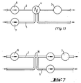
- the device 1 for processing the liquid sample essentially consists of a feed line 2 to a detector 3, an injection valve 4 and a feed line 5 to this injection valve 4.
- This arrangement can be seen as a circuit diagram in FIG. 1, a pump 6 and 7 being arranged at the beginning of the feed lines 2 and 5, which are integrated within the device 1 in the following exemplary embodiments.
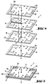
- Both this very simply constructed device 1 according to FIG. 1 and the devices 1 of this type described below with more individual line sections or functional parts 2 to 5 and 8 to 15 can each be assembled from a stack of plate-shaped components 8.
- These components 8 each differ in terms of their design with respect to line parts 9, flow openings 10, valves 11 or central chambers 12. Nevertheless, the components are all designated "8" below, since they have a matching outer contour within a kit of a device 1 and are stacked congruently on top of each other.
- the very simple design acc. 1 to 5 already shows that the components 8 each contain line pieces 9 and branches 13 and flow openings 10 in order to bring the lines 2 and 5 together at an injection point with an internal volume corresponding to the injection valve 4, after which the line 5 is discharged again , while line 2 can be continued to an external detector.
- stackable components 8 on the device 1 according to FIG. 1 save a considerable amount of space and internal volume, so that correspondingly little sample liquid and little carrier liquid are required for the actual analysis.
- Fig. 6 the device 1, which is composed of stackable components 8 with different functions, is shown only as a block. It can be seen from this that storage vessels 14 can be provided outside of the actual device 1, which are connected to the device 1 via conventional hoses or lines 15, it being provided in FIG. 6 that pumps 6 and 7 are described in a manner yet to be described are arranged within the device 1.
- Figure 6 also shows connections e.g. in the form of electrical cables 16, with which the device 1 can be connected to electronic signal evaluations 17 or optical signal evaluations 18.
- the device 1 according to FIG. 1 is compared with an injection valve 4, a flow diagram of such a device 1 with two T-pieces 19 located one behind the other, both in front of and behind these T-pieces 19 on the line 2 a pump is present, while a suction pump is also present behind the second T-piece on branch line 5, so that the desired injection from line 5 into line 2 can be carried out by controlling all of these pumps.
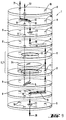
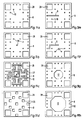
- 9 and 10 show a device 1 in which a total of nine plate-shaped components 8 are stacked to form a device 1.
- 9 shows that components 8 contain flow openings 10, valves 11, chambers 12 and also branches 13 and line parts 9 in a specific order in order to reach an outlet 21 from a lower inlet 20.
- a flexible membrane 24 is inserted between these components 8, this can be used as a pump 6 or 7 by applying pressure or vacuum from one side is deflected so that it can exert a corresponding pumping effect on the chambers 12 on its other side by the deflection.
- the pressure line 22 used to move such a membrane is indicated by dashed lines and also leads via flow openings 10 and line parts 9 on the corresponding components 8 to the actuating chamber 12 below the flexible membrane.
- a flow opening 23 passing through a component is funnel-shaped at least in regions over the thickness of the component 8 and - which is because the smallness of the representation can only be seen schematically - can contain a spherical valve element in its tapering section. This means that the flow can only take place in one direction, i.e. such a component contains a check valve. This can ensure that the pump formed by a flexible membrane 24 between two chambers 12 is effective in the desired direction of delivery.
- kits of the device 1 can be arranged within the kit of the device 1 on plate-shaped components 8 or between them in a very space-saving manner.
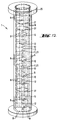
- 10 gives an impression of how small the overall external dimension of the device 1 is when the individual plate-shaped components 8 are firmly connected as an associated stack, the kit also including end plates 25 with connections as inlet 20 and outlet 21 to the flow channels of the device 1 has. Such end plates are also in the embodiments of FIGS. 11 u. 12 recognizable.
- FIG. 11 shows an embodiment in which, in the manner described above, two pumps, namely a pump 6 for carrier liquid and a pump 7 for the sample, are accommodated within a device 1 made of stacked plate-shaped components, these pumps 6 and 7 in turn two plates are formed with chambers 12 and a membrane located between them. Correspondingly more inlets and outlets for pump control or pump actuation are provided on the upper cover plate 25. Nevertheless, this extended device 1 according to FIG. 11 overall, a very small space requirement within the stack of components 8 with a correspondingly small internal total volume.
- components 8 occur several times, and in particular such components 8 with peripheral flow openings 10 can be used several times, depending on the course of the overall line, so that they can be rotated relative to one another in such a way that they produce the corresponding connections to line parts 9 in parallel components 8 can, so that a continuous wiring harness is created from the inlet 20 to the outlet 21, as is also realized in FIG. 11 in a somewhat simpler version of a device 1.
- the plate-shaped components 8 have a circular outer contour and are, for example, glass, plastic or metal disks with about 50 mm or a larger diameter
- the embodiments shown in FIG. 4 and 5 and 13a-h to 15 analog usable and assemblable plate-shaped components 8, which are wafers separated from a crystal in a chip-like manner and can therefore have an even smaller outer dimension, because the perforations, channel sections and the like present on them can be made in the etching process.
- these components 8 have a square outer contour.
- FIGS. 13a-h Especially in the example of a kit shown in FIGS. 13a-h, the individual parts of which may be present multiple times, line parts 9, flow openings 10 or chambers 12, of different sizes, which can be mixing chambers or also pump elements, can again be seen. Furthermore, it is indicated in the component 8 shown in FIG. 13d that adapters 26 can be provided for holding glass capillaries, with which a supply of samples and the like can be carried out. Furthermore, in FIG. 13c, winding channels 27 can be seen, which can also be accommodated in very narrow turns on a very small component using the etching technique already mentioned, that is to say they give the possibility of achieving a mixing effect through numerous bends and turns in a very small space. Such winding channels 27 are also shown in FIG. 12.
- Fig. 14 is a component 8, which has an inlet and an outlet to a channel section 29, which is mirrored at its two ends 30, so as to form an optical detector cell.
- an ion-selective field effect transistor 31 is arranged on both sides of a comparable channel section 29, which in turn has an inlet and an outlet, whereby this component 8 becomes an electrochemical detector cell.
- the connections 32 of this transistor 31, like this itself, can be attached in a simple manner in the known semiconductor construction.
- the opposite surfaces of the plate-shaped components 8 are each plane-parallel and flat, they can each seal the edges of the flow openings 10 or also of channels or channel sections 29, 27 or 9 and the chambers 12 in the layered and connected position of use.
- the stacking thus results in a device 1 in which the individual line areas and functional parts are tight and do not require any additional seals.
- threaded rods or screws penetrating the connection or positioning perforations 28 can be provided in a manner not shown in detail.
- the device 1 for the preparation or preparation of liquid samples for a preferably quantitative chemical analysis, in particular for flow-injection analysis is composed of a set of plate-shaped components 8 to form a stack in order to miniaturize and reduce the required sample volume while simultaneously reducing the analysis time, the Components 8 each have pipe sections 9 and / or branches 13 and / or orifices and / or valves, for example Check valves and pumps contain 6.7 in order to be able to supply carrier liquid and sample to a detector 3 in the desired manner.
- the components 8 with the lines and functional parts they contain can be stacked in different numbers and / or sequences and / or mutual angular orientation and tightly connected in the position of use.
Claims (17)
- Dispositif de mise en état ou de préparation d'échantillons liquides pour l'analyse chimique, ce dispositif comportant des canaux d'alimentation, ou conduits d'alimentation, menant à un dispositif d'analyse ou à un détecteur, au moins un conduit pour transporter le véhicule fluide et au moins un autre conduit destiné au transport d'un échantillon à analyser et débouchant dans le conduit d'alimentation en véhicule fluide, étant prévus, le dispositif (1) pouvant être assemblé de façon modulaire à partir d'un jeu de pièces constitutives (8) en forme de plaques, pour former un empilement, et les pièces constitutives (8) comportant chacune des tronçons de conduits (9), des ramifications (13) et/ou des embouchures, caractérisé en ce que le dispositif (1) constitué de façon modulaire de pièces constitutives (8) empilées les unes au-dessus des autres, présente au moins une pompe intégrée qui est formée par une membrane, disposée entre deux pièces constitutives (8), qui peut être déformée à partir d'un côté au moyen d'une pression et/ou d'une dépression et qui est reliée de son autre côté à des conduits d'aspiration et de pression destinés à transporter un fluide qui doit être pompé.
- Dispositif selon la revendication 1, caractérisé en ce qu'au moins une pièce constitutive (8) contient une ou plusieurs valves (11).
- Dispositif selon la revendication 1 ou 2, caractérisé en ce que les pièces constitutives (8) peuvent être empilées en vue de la constitution de systèmes d'écoulement différents et de conduits en nombre différent et/ou en ordre différent et/ou dans une orientation mutuelle différente, et en ce qu'elles sont reliées de façon étanche lorsqu'elles sont en position d'utilisation.
- Dispositif selon l'une des revendications 1 à 3, caractérisé en ce que chacune des pièces constitutives (8) en forme de plaques présente, en plus de la pompe intégrée, au moins une valve (11), ou une chambre de mélangeage (12) ou un élément de pompe (6, 7), ou des extracteurs, ou des réacteurs, ou des pièces de liaison et/ou des éléments de détection en particulier des éléments de détection photo-optiques, électrochimiques, travaillant par électrophorèse, ou chromatographiques ou similaires, ou une autre partie fonctionnelle du dispositif.
- Dispositif selon la revendication 4, caractérisé en ce que la partie fonctionnelle prévue sur la pièce constitutive (8) est disposée au centre de celle-ci et en ce que des canaux d'alimentation et des canaux d'évacuation, ou des orifices (10) de passage similaires sont situés plus près du bord, ou de la périphérie, de la pièce constitutive (8).
- Dispositif selon l'une des revendications 1 à 5, caractérisé en ce que le raccordement à un appareil de commande s'effectue par l'intermédiaire de câbles électriques, en particulier pour le détecteur, la pompe et/ou les valves, par l'intermédiaire de conduits en tuyau souple hydrauliques et/ou pneumatiques, par exemple pour les pompes ou les valves, ou par l'intermédiaire de tuyaux souples d'alimentation en réactif et de fibres optiques, en particulier en ce qui concerne un détecteur dont le fonctionnement est basé sur l'éclairage au moyen d'une lumière.
- Dispositif selon l'une des revendications 1 à 6, caractérisé en ce que les pièces constitutives individuelles comportent, à des emplacements qui se correspondent dans chaque cas, des trous (28) ou cavités de centrage, de positionnement ou de liaison.
- Dispositif selon l'une des revendications 1 à 7, caractérisé en ce que chaque pièce constitutive (8) présente sur sa périphérie plusieurs, par exemple quatre, trous de centrage ou de liaison destinés à des moyens de fixation qui sont décalés chacun par rapport aux autres d'un angle qui coïncide exactement, et à une distance du centre de la pièce constitutive qui coïncide exactement.
- Dispositif selon l'une des revendications 1 à 8, caractérisé en ce que les contours extérieurs des pièces constitutives (8) se correspondent exactement et ont la même dimension, si bien que les pièces constitutives se recouvrent exactement.
- Dispositif selon la revendication 9, caractérisé en ce que le contour extérieur des pièces constitutives (8) est rond ou carré.
- Dispositif selon l'une des revendications 1 à 10, caractérisé en ce que les pièces constitutives (8) en forme de plaques sont des disques en verre, en matière plastique, ou en métal, en particulier des disques en acier spécial.
- Dispositif selon l'une des revendications 1 à 10, caractérisé en ce que les pièces constitutives (8) en forme de plaques sont des disques du genre de micro-plaquettes détachées d'un cristal.
- Dispositif selon l'une des revendications 4 à 12, caractérisé en ce que les orifices de passage, les canaux de passage et/ou les trous de liaison et/ou les cavités destinées aux pièces fonctionnelles sont réalisées par morsure à l'acide dans les pièces constitutives (8).
- Dispositif selon l'une des revendications 1 à 13, caractérisé en ce que les surfaces situées face à face des pièces constitutives (8) en forme de plaques sont planes et parallèles de façon telle qu'en position d'empilage et de liaison, les bords des orifices de passage (10) et similaires, ou les tronçons (9, 27, 29) de canal ouverts d'un côté vers la surface, sont étanchéifiés.
- Dispositif selon l'une des revendications 1 à 14,caractérisé en ce que, en vue de réaliser une valve, un orifice de passage (23) traversant une pièce constitutive (8) a une forme d'entonnoir au moins sur une certaine zone de l'épaisseur de la pièce constitutive et contient un élément de valve en forme de bille dans sa partie qui se rétrécit en forme d'entonnoir.
- Dispositif selon l'une des revendications 7 à 15, caractérisé en ce que sont prévues des tiges filetées ou des vis traversant les trous de liaison (28) en vue de serrer de façon étanche les pièces constitutives (8) en forme de plaques.
- Dispositif selon l'une des revendications 1 à 16, caractérisé en ce que l'ensemble de structure comporte des disques terminaux (25) dotés d'éléments de raccordement aux canaux d'écoulement.
Applications Claiming Priority (2)
| Application Number | Priority Date | Filing Date | Title |
|---|---|---|---|
| CH346790 | 1990-11-01 | ||
| CH3467/90 | 1990-11-01 |
Publications (2)
| Publication Number | Publication Date |
|---|---|
| EP0484278A1 EP0484278A1 (fr) | 1992-05-06 |
| EP0484278B1 true EP0484278B1 (fr) | 1995-04-12 |
Family
ID=4256589
Family Applications (1)
| Application Number | Title | Priority Date | Filing Date |
|---|---|---|---|
| EP91810819A Expired - Lifetime EP0484278B1 (fr) | 1990-11-01 | 1991-10-23 | Appareil de préparation d'échantillons liquides pour l'analyse chimique |
Country Status (4)
| Country | Link |
|---|---|
| US (1) | US5250263A (fr) |
| EP (1) | EP0484278B1 (fr) |
| JP (1) | JPH04307349A (fr) |
| DE (1) | DE59105165D1 (fr) |
Cited By (1)
| Publication number | Priority date | Publication date | Assignee | Title |
|---|---|---|---|---|
| US6056860A (en) * | 1996-09-18 | 2000-05-02 | Aclara Biosciences, Inc. | Surface modified electrophoretic chambers |
Families Citing this family (144)
| Publication number | Priority date | Publication date | Assignee | Title |
|---|---|---|---|---|
| US6176962B1 (en) | 1990-02-28 | 2001-01-23 | Aclara Biosciences, Inc. | Methods for fabricating enclosed microchannel structures |
| US6943034B1 (en) | 1991-11-22 | 2005-09-13 | Affymetrix, Inc. | Combinatorial strategies for polymer synthesis |
| EP0624059A4 (en) * | 1991-11-22 | 1994-12-21 | Affymax Technologies N.V. | Combinatorial strategies for polymer synthesis. |
| CH684554A5 (de) * | 1992-09-22 | 1994-10-14 | Sotax Ag | Probensammler. |
| EP0620432B1 (fr) * | 1993-04-15 | 2004-08-25 | Zeptosens AG | Méthode pour contrôler l'introduction d'un échantillon en séparation par micro colonnes et appareil d'échantillonage |
| US20050042149A1 (en) * | 1994-04-01 | 2005-02-24 | Integrated Chemical Synthesizers, Inc. | Nanoscale chemical synthesis |
| US5580523A (en) * | 1994-04-01 | 1996-12-03 | Bard; Allen J. | Integrated chemical synthesizers |
| US6129973A (en) * | 1994-07-29 | 2000-10-10 | Battelle Memorial Institute | Microchannel laminated mass exchanger and method of making |
| US5811062A (en) * | 1994-07-29 | 1998-09-22 | Battelle Memorial Institute | Microcomponent chemical process sheet architecture |
| US6001229A (en) * | 1994-08-01 | 1999-12-14 | Lockheed Martin Energy Systems, Inc. | Apparatus and method for performing microfluidic manipulations for chemical analysis |
| FI100859B (sv) * | 1994-10-14 | 1998-03-13 | Bjarne Holmbom | Förfarande och anordning för att utföra on-line flödesextraktion av ex traherbara komponenter i vätskor |
| KR100314996B1 (ko) * | 1994-11-10 | 2002-01-15 | 윌리암 제이. 버크 | 액체분배시스템 |
| US5585069A (en) * | 1994-11-10 | 1996-12-17 | David Sarnoff Research Center, Inc. | Partitioned microelectronic and fluidic device array for clinical diagnostics and chemical synthesis |
| US5632876A (en) * | 1995-06-06 | 1997-05-27 | David Sarnoff Research Center, Inc. | Apparatus and methods for controlling fluid flow in microchannels |
| DE19507638C2 (de) * | 1995-03-04 | 1997-09-25 | Danfoss As | Analysenvorrichtung |
| WO1996039260A1 (fr) * | 1995-06-06 | 1996-12-12 | David Sarnoff Research Center, Inc. | Procede de fabrication de conduits micro-electriques |
| US6120665A (en) * | 1995-06-07 | 2000-09-19 | Chiang; William Yat Chung | Electrokinetic pumping |
| EP0839318B1 (fr) * | 1995-06-16 | 2003-05-07 | University of Washington | Procede et dispositif miniaturise d'extraction differentielle |
| US5716852A (en) * | 1996-03-29 | 1998-02-10 | University Of Washington | Microfabricated diffusion-based chemical sensor |
| US6454945B1 (en) | 1995-06-16 | 2002-09-24 | University Of Washington | Microfabricated devices and methods |
| US6048734A (en) | 1995-09-15 | 2000-04-11 | The Regents Of The University Of Michigan | Thermal microvalves in a fluid flow method |
| US20010055812A1 (en) * | 1995-12-05 | 2001-12-27 | Alec Mian | Devices and method for using centripetal acceleration to drive fluid movement in a microfluidics system with on-board informatics |
| US5948684A (en) * | 1997-03-31 | 1999-09-07 | University Of Washington | Simultaneous analyte determination and reference balancing in reference T-sensor devices |
| US20030211507A1 (en) * | 1996-03-29 | 2003-11-13 | Anson Hatch | Microscale diffusion immunoassay in hydrogels |
| US6541213B1 (en) | 1996-03-29 | 2003-04-01 | University Of Washington | Microscale diffusion immunoassay |
| US5840256A (en) * | 1996-04-09 | 1998-11-24 | David Sarnoff Research Center Inc. | Plate for reaction system |
| US6033544A (en) * | 1996-10-11 | 2000-03-07 | Sarnoff Corporation | Liquid distribution system |
| US5871698A (en) * | 1996-05-02 | 1999-02-16 | Sandia Corporation | Chemical sensing flow probe |
| US5971158A (en) * | 1996-06-14 | 1999-10-26 | University Of Washington | Absorption-enhanced differential extraction device |
| US6110343A (en) | 1996-10-04 | 2000-08-29 | Lockheed Martin Energy Research Corporation | Material transport method and apparatus |
| US6447727B1 (en) * | 1996-11-19 | 2002-09-10 | Caliper Technologies Corp. | Microfluidic systems |
| US6465257B1 (en) | 1996-11-19 | 2002-10-15 | Caliper Technologies Corp. | Microfluidic systems |
| US6056859A (en) * | 1997-02-12 | 2000-05-02 | Lockheed Martin Energy Research Corporation | Method and apparatus for staining immobilized nucleic acids |
| WO1998049344A1 (fr) | 1997-04-28 | 1998-11-05 | Lockheed Martin Energy Research Corporation | Methode et appareil d'analyse d'acides nucleiques |
| US5985214A (en) | 1997-05-16 | 1999-11-16 | Aurora Biosciences Corporation | Systems and methods for rapidly identifying useful chemicals in liquid samples |
| US6090251A (en) * | 1997-06-06 | 2000-07-18 | Caliper Technologies, Inc. | Microfabricated structures for facilitating fluid introduction into microfluidic devices |
| US5900130A (en) * | 1997-06-18 | 1999-05-04 | Alcara Biosciences, Inc. | Method for sample injection in microchannel device |
| US6190616B1 (en) | 1997-09-11 | 2001-02-20 | Molecular Dynamics, Inc. | Capillary valve, connector, and router |
| US6007775A (en) | 1997-09-26 | 1999-12-28 | University Of Washington | Multiple analyte diffusion based chemical sensor |
| US6136272A (en) * | 1997-09-26 | 2000-10-24 | University Of Washington | Device for rapidly joining and splitting fluid layers |
| WO1999019717A1 (fr) | 1997-10-15 | 1999-04-22 | Aclara Biosciences, Inc. | Dispositif a microstructure stratifiee et procede de fabrication de ce dispositif |
| US6153076A (en) * | 1998-01-12 | 2000-11-28 | The Regents Of The University Of California | Extended length microchannels for high density high throughput electrophoresis systems |
| US6224830B1 (en) * | 1998-01-30 | 2001-05-01 | The Governors Of The University Of Alberta | Absorbance cell for microfluid devices |
| US6117396A (en) * | 1998-02-18 | 2000-09-12 | Orchid Biocomputer, Inc. | Device for delivering defined volumes |
| US6123798A (en) * | 1998-05-06 | 2000-09-26 | Caliper Technologies Corp. | Methods of fabricating polymeric structures incorporating microscale fluidic elements |
| DE19821627A1 (de) * | 1998-05-14 | 1999-11-18 | Bayer Ag | Mikrostrukturierte Folien |
| WO1999060397A1 (fr) * | 1998-05-18 | 1999-11-25 | University Of Washington | Cartouche d'analyse liquide |
| US6830729B1 (en) | 1998-05-18 | 2004-12-14 | University Of Washington | Sample analysis instrument |
| US6062261A (en) * | 1998-12-16 | 2000-05-16 | Lockheed Martin Energy Research Corporation | MicrofluIdic circuit designs for performing electrokinetic manipulations that reduce the number of voltage sources and fluid reservoirs |
| US6294063B1 (en) * | 1999-02-12 | 2001-09-25 | Board Of Regents, The University Of Texas System | Method and apparatus for programmable fluidic processing |
| DE29903296U1 (de) * | 1999-02-24 | 2000-08-03 | Cpc Cellular Process Chemistry | Mikroreaktor |
| US6192596B1 (en) | 1999-03-08 | 2001-02-27 | Battelle Memorial Institute | Active microchannel fluid processing unit and method of making |
| US6296702B1 (en) * | 1999-03-15 | 2001-10-02 | Pe Corporation (Ny) | Apparatus and method for spotting a substrate |
| US6149815A (en) * | 1999-11-23 | 2000-11-21 | Sauter; Andrew D. | Precise electrokinetic delivery of minute volumes of liquid(s) |
| US20020112961A1 (en) * | 1999-12-02 | 2002-08-22 | Nanostream, Inc. | Multi-layer microfluidic device fabrication |
| US6790328B2 (en) | 2000-01-12 | 2004-09-14 | Ut-Battelle, Llc | Microfluidic device and method for focusing, segmenting, and dispensing of a fluid stream |
| US7435392B2 (en) * | 2000-02-03 | 2008-10-14 | Acclavis, Llc | Scalable continuous production system |
| US7056477B1 (en) | 2000-02-03 | 2006-06-06 | Cellular Process Chemistry, Inc. | Modular chemical production system incorporating a microreactor |
| US7241423B2 (en) * | 2000-02-03 | 2007-07-10 | Cellular Process Chemistry, Inc. | Enhancing fluid flow in a stacked plate microreactor |
| ATE382858T1 (de) * | 2000-02-23 | 2008-01-15 | Caliper Life Sciences Inc | Mehrfach-reservoir-drucksteuersystem |
| US6890489B2 (en) * | 2000-04-26 | 2005-05-10 | Rheodyne, L.P. | Mass rate attenuator |
| KR100430864B1 (ko) * | 2000-04-28 | 2004-05-10 | (주)소노스 | 전자유체 통합 다층 인쇄회로기판 |
| US7413714B1 (en) | 2000-07-16 | 2008-08-19 | Ymc Co. Ltd. | Sequential reaction system |
| DE10036602A1 (de) * | 2000-07-27 | 2002-02-14 | Cpc Cellular Process Chemistry | Mikroreaktor für Reaktionen zwischen Gasen und Flüssigkeiten |
| WO2002011887A1 (fr) * | 2000-08-03 | 2002-02-14 | Caliper Technologies Corp. | Procedes et dispositifs pour la distribution de fluides avec une production elevee |
| US8048386B2 (en) | 2002-02-25 | 2011-11-01 | Cepheid | Fluid processing and control |
| US6852291B1 (en) * | 2000-10-11 | 2005-02-08 | Innovadyne Technologies, Inc. | Hybrid valve apparatus and method for fluid handling |
| US7135146B2 (en) * | 2000-10-11 | 2006-11-14 | Innovadyne Technologies, Inc. | Universal non-contact dispense peripheral apparatus and method for a primary liquid handling device |
| WO2002068823A1 (fr) | 2000-11-06 | 2002-09-06 | Nanostream Inc. | Composants microfluidiques a ecoulement unidirectionnel |
| US6692700B2 (en) | 2001-02-14 | 2004-02-17 | Handylab, Inc. | Heat-reduction methods and systems related to microfluidic devices |
| DE10106996C2 (de) * | 2001-02-15 | 2003-04-24 | Merck Patent Gmbh | Einrichtung zur Verbindung von Mikrokomponenten |
| US7323140B2 (en) | 2001-03-28 | 2008-01-29 | Handylab, Inc. | Moving microdroplets in a microfluidic device |
| US6852287B2 (en) | 2001-09-12 | 2005-02-08 | Handylab, Inc. | Microfluidic devices having a reduced number of input and output connections |
| US7829025B2 (en) | 2001-03-28 | 2010-11-09 | Venture Lending & Leasing Iv, Inc. | Systems and methods for thermal actuation of microfluidic devices |
| US7192557B2 (en) | 2001-03-28 | 2007-03-20 | Handylab, Inc. | Methods and systems for releasing intracellular material from cells within microfluidic samples of fluids |
| US8895311B1 (en) | 2001-03-28 | 2014-11-25 | Handylab, Inc. | Methods and systems for control of general purpose microfluidic devices |
| US6575188B2 (en) | 2001-07-26 | 2003-06-10 | Handylab, Inc. | Methods and systems for fluid control in microfluidic devices |
| US7010391B2 (en) | 2001-03-28 | 2006-03-07 | Handylab, Inc. | Methods and systems for control of microfluidic devices |
| US7270786B2 (en) | 2001-03-28 | 2007-09-18 | Handylab, Inc. | Methods and systems for processing microfluidic samples of particle containing fluids |
| US7201873B2 (en) * | 2001-04-16 | 2007-04-10 | Tosoh Corporation | Fine channel device, method for producing the fine channel device and use of the same |
| US7097347B2 (en) * | 2001-05-07 | 2006-08-29 | Uop Llc | Static mixer and process for mixing at least two fluids |
| DE60234176D1 (de) * | 2001-05-10 | 2009-12-10 | Chempaq As | Vorrichtung zur probeentnahme kleiner und genauer flüssigkeitsvolumen |
| US7318912B2 (en) * | 2001-06-07 | 2008-01-15 | Nanostream, Inc. | Microfluidic systems and methods for combining discrete fluid volumes |
| US6981522B2 (en) * | 2001-06-07 | 2006-01-03 | Nanostream, Inc. | Microfluidic devices with distributing inputs |
| US20020186263A1 (en) * | 2001-06-07 | 2002-12-12 | Nanostream, Inc. | Microfluidic fraction collectors |
| DE10152690A1 (de) * | 2001-10-19 | 2003-05-08 | Genescan Europ Ag | Durchflussreaktionskammer für Sensorchips |
| DE10155010A1 (de) * | 2001-11-06 | 2003-05-15 | Cpc Cellular Process Chemistry | Mikroreaktorsystem |
| US7069952B1 (en) | 2001-11-14 | 2006-07-04 | Caliper Life Sciences, Inc. | Microfluidic devices and methods of their manufacture |
| US6739576B2 (en) | 2001-12-20 | 2004-05-25 | Nanostream, Inc. | Microfluidic flow control device with floating element |
| EP1470427B1 (fr) | 2002-01-25 | 2007-11-07 | Innovadyne Technologies, Inc. | Procede de distribution de faibles volumes de liquide sans contact |
| US20040021741A1 (en) * | 2002-07-30 | 2004-02-05 | Ottenheimer Thomas H. | Slotted substrate and method of making |
| DE10234819A1 (de) * | 2002-07-31 | 2004-02-19 | Roche Diagnostics Gmbh | Testvorrichtung zur Untersuchung einer biologischen Probenflüssigkeit |
| AU2003284055A1 (en) * | 2002-10-09 | 2004-05-04 | The Board Of Trustees Of The University Of Illinois | Microfluidic systems and components |
| EP1567796B1 (fr) * | 2002-12-04 | 2008-05-28 | Spinx, Inc. | Dispositifs et procedes de manipulation de fluides programmable a petite echelle |
| FR2852603B1 (fr) * | 2003-03-20 | 2005-05-13 | Installation automatisee pour la detection de la fixation de biomolecules sur un echantillon en trois dimensions | |
| WO2004092908A2 (fr) * | 2003-04-14 | 2004-10-28 | Cellular Process Chemistry, Inc. | Systeme et procede de determination de parametres de reaction optimaux au moyen d'un processus continu |
| US6826949B1 (en) * | 2003-06-13 | 2004-12-07 | Becton, Dickinson And Company | Method and apparatus for guiding a liquid sample towards a sensing surface |
| JP4996248B2 (ja) | 2003-07-31 | 2012-08-08 | ハンディーラブ インコーポレイテッド | 粒子含有サンプルの処理 |
| US7032605B1 (en) | 2003-10-15 | 2006-04-25 | Douglas B. Dority | Dual piston rotary valve |
| US8066955B2 (en) * | 2003-10-17 | 2011-11-29 | James M. Pinchot | Processing apparatus fabrication |
| US6994245B2 (en) * | 2003-10-17 | 2006-02-07 | James M. Pinchot | Micro-reactor fabrication |
| US20050084072A1 (en) * | 2003-10-17 | 2005-04-21 | Jmp Industries, Inc., An Ohio Corporation | Collimator fabrication |
| US8852862B2 (en) | 2004-05-03 | 2014-10-07 | Handylab, Inc. | Method for processing polynucleotide-containing samples |
| WO2005108620A2 (fr) | 2004-05-03 | 2005-11-17 | Handylab, Inc. | Traitement d'échantillons contenant des polynucléotides |
| EP1765501A1 (fr) | 2004-05-28 | 2007-03-28 | Board of Regents, The University of Texas System | Processeurs fluidiques programmables |
| WO2006036592A1 (fr) * | 2004-09-23 | 2006-04-06 | University Of Washington | Immuno-essai de diffusion a micro-echelle utilisant des reactifs polyvalents |
| ES2692380T3 (es) | 2006-03-24 | 2018-12-03 | Handylab, Inc. | Método para realizar PCR con un cartucho con varias pistas |
| US10900066B2 (en) | 2006-03-24 | 2021-01-26 | Handylab, Inc. | Microfluidic system for amplifying and detecting polynucleotides in parallel |
| US11806718B2 (en) | 2006-03-24 | 2023-11-07 | Handylab, Inc. | Fluorescence detector for microfluidic diagnostic system |
| US7998708B2 (en) | 2006-03-24 | 2011-08-16 | Handylab, Inc. | Microfluidic system for amplifying and detecting polynucleotides in parallel |
| US8883490B2 (en) | 2006-03-24 | 2014-11-11 | Handylab, Inc. | Fluorescence detector for microfluidic diagnostic system |
| US8088616B2 (en) | 2006-03-24 | 2012-01-03 | Handylab, Inc. | Heater unit for microfluidic diagnostic system |
| JP2010508500A (ja) * | 2006-10-31 | 2010-03-18 | ビィウルケルト ヴェルケ ゲゼルシャフト ミット ベシュレンクテル ハフツング ウント コンパニー カーゲー | 液体の分析および合成のためのモジューラ試験室機器と液体の分析および合成の方法 |
| WO2008061165A2 (fr) | 2006-11-14 | 2008-05-22 | Handylab, Inc. | Cartouche microfluidique et son procédé de fabrication |
| WO2008106613A2 (fr) * | 2007-02-28 | 2008-09-04 | Waters Investments Limited | Appareil de chromatographie en phase liquide ayant des composants titane liés par diffusion |
| WO2008121803A1 (fr) * | 2007-03-30 | 2008-10-09 | Fujifilm Corporation | Procédé de nettoyage de cannaux de microécoulement |
| USD621060S1 (en) | 2008-07-14 | 2010-08-03 | Handylab, Inc. | Microfluidic cartridge |
| US20090136385A1 (en) | 2007-07-13 | 2009-05-28 | Handylab, Inc. | Reagent Tube |
| US8287820B2 (en) | 2007-07-13 | 2012-10-16 | Handylab, Inc. | Automated pipetting apparatus having a combined liquid pump and pipette head system |
| US9618139B2 (en) | 2007-07-13 | 2017-04-11 | Handylab, Inc. | Integrated heater and magnetic separator |
| US9186677B2 (en) | 2007-07-13 | 2015-11-17 | Handylab, Inc. | Integrated apparatus for performing nucleic acid extraction and diagnostic testing on multiple biological samples |
| US8182763B2 (en) | 2007-07-13 | 2012-05-22 | Handylab, Inc. | Rack for sample tubes and reagent holders |
| US8133671B2 (en) | 2007-07-13 | 2012-03-13 | Handylab, Inc. | Integrated apparatus for performing nucleic acid extraction and diagnostic testing on multiple biological samples |
| US8105783B2 (en) | 2007-07-13 | 2012-01-31 | Handylab, Inc. | Microfluidic cartridge |
| AU2008276211B2 (en) | 2007-07-13 | 2015-01-22 | Handylab, Inc. | Polynucleotide capture materials, and methods of using same |
| US20090075801A1 (en) * | 2007-09-19 | 2009-03-19 | Dalibor Hodko | Counter-centrifugal force device |
| EP2235517B1 (fr) * | 2007-12-31 | 2018-08-01 | O. I. Corporation | Système et procédé de régulation de l'écoulement dans des dispositifs fluidiques |
| USD618820S1 (en) | 2008-07-11 | 2010-06-29 | Handylab, Inc. | Reagent holder |
| USD787087S1 (en) | 2008-07-14 | 2017-05-16 | Handylab, Inc. | Housing |
| DE202009007800U1 (de) * | 2009-06-04 | 2009-08-20 | Bürkert Werke GmbH & Co. KG | Modulares Fließinjektions-Analysesystem |
| EP2437887B1 (fr) | 2009-06-04 | 2016-05-11 | Lockheed Martin Corporation | Puce microfluidique de plusieurs échantillon pour analyse de dna |
| DE102010030489A1 (de) * | 2010-03-25 | 2011-09-29 | Endress + Hauser Conducta Gesellschaft für Mess- und Regeltechnik mbH + Co. KG | System zu Behandlung von Flüssigkeiten |
| US9095850B2 (en) | 2010-03-25 | 2015-08-04 | Endress + Hauser Conducta Gesellschaft für Mess—und Regeltechnik mbH + Co. KG | System for treating liquids |
| JP5892551B2 (ja) * | 2010-06-30 | 2016-03-23 | 株式会社メタボスクリーン | マイクロ化学チップ、その製造方法、及びその使用方法 |
| CA2814720C (fr) | 2010-10-15 | 2016-12-13 | Lockheed Martin Corporation | Conception optique microfluidique |
| ES2769028T3 (es) | 2011-04-15 | 2020-06-24 | Becton Dickinson Co | Termociclador microfluídico de barrido en tiempo real |
| DK3273253T3 (da) | 2011-09-30 | 2020-10-12 | Becton Dickinson Co | Forenet reagensstrimmel |
| USD692162S1 (en) | 2011-09-30 | 2013-10-22 | Becton, Dickinson And Company | Single piece reagent holder |
| CN104040238B (zh) | 2011-11-04 | 2017-06-27 | 汉迪拉布公司 | 多核苷酸样品制备装置 |
| CN107881219B (zh) | 2012-02-03 | 2021-09-10 | 贝克顿·迪金森公司 | 用于分子诊断测试分配和测试之间兼容性确定的外部文件 |
| US9322054B2 (en) | 2012-02-22 | 2016-04-26 | Lockheed Martin Corporation | Microfluidic cartridge |
| HUE051039T2 (hu) * | 2015-04-14 | 2021-01-28 | Keofitt As | Mintavevõ eszköz fluidum-mintáknak fluidumot tartalmazó tartályból való kinyerésére |
| US11035480B2 (en) * | 2016-02-24 | 2021-06-15 | Leanna Levine and Aline, Inc. | Mechanically driven sequencing manifold |
| BE1029473B1 (nl) * | 2021-06-08 | 2023-01-16 | Pharmafluidics | Generiek ontwerp voor microfluïdisch apparaat |
Family Cites Families (12)
| Publication number | Priority date | Publication date | Assignee | Title |
|---|---|---|---|---|
| US3404780A (en) * | 1965-05-25 | 1968-10-08 | Centraia Automationslaboratori | Automatic filter |
| US4086060A (en) * | 1976-10-22 | 1978-04-25 | Jocelyn Dickson | Disposable manipulative laboratory device for transferring biological fluids |
| US4254084A (en) * | 1978-04-21 | 1981-03-03 | Blum Alvin S | Method and apparataus for automatic isoenzyme analysis |
| GB2097692B (en) * | 1981-01-10 | 1985-05-22 | Shaw Stewart P D | Combining chemical reagents |
| DK429682A (da) * | 1982-09-28 | 1984-03-29 | Inflow Aps | Integrerede mikroroersystemer til kontinuerlig gennemstroemningsanalyse |
| US4801308A (en) * | 1983-10-03 | 1989-01-31 | Keefer Bowie | Apparatus and process for pressure swing adsorption separation |
| DE3565986D1 (en) * | 1984-05-02 | 1988-12-08 | Brendan James Hamill | An apparatus for the chemical synthesis of oligonucleotides |
| US4702889A (en) * | 1986-01-16 | 1987-10-27 | Coulter Electronics Inc. | Liquid sampling valve |
| EP0243310A3 (fr) * | 1986-04-18 | 1989-10-18 | Ciba-Geigy Ag | Procédé pour régler et optimaliser les processus industriels |
| DE3737604A1 (de) * | 1987-11-05 | 1989-05-24 | Biotechnolog Forschung Gmbh | Geraet zur fliess-injektions-analyse |
| DE3813671A1 (de) * | 1988-04-22 | 1989-11-02 | Europ Lab Molekularbiolog | Vorrichtung zur durchfuehrung chemischer reaktionsfolgen |
| US4948565A (en) * | 1989-04-25 | 1990-08-14 | Fisher Scientific Company | Analytical system |
-
1991
- 1991-10-23 EP EP91810819A patent/EP0484278B1/fr not_active Expired - Lifetime
- 1991-10-23 DE DE59105165T patent/DE59105165D1/de not_active Expired - Lifetime
- 1991-10-30 US US07/785,134 patent/US5250263A/en not_active Expired - Lifetime
- 1991-11-01 JP JP3313364A patent/JPH04307349A/ja active Pending
Cited By (1)
| Publication number | Priority date | Publication date | Assignee | Title |
|---|---|---|---|---|
| US6056860A (en) * | 1996-09-18 | 2000-05-02 | Aclara Biosciences, Inc. | Surface modified electrophoretic chambers |
Also Published As
| Publication number | Publication date |
|---|---|
| JPH04307349A (ja) | 1992-10-29 |
| EP0484278A1 (fr) | 1992-05-06 |
| US5250263A (en) | 1993-10-05 |
| DE59105165D1 (de) | 1995-05-18 |
Similar Documents
| Publication | Publication Date | Title |
|---|---|---|
| EP0484278B1 (fr) | Appareil de préparation d'échantillons liquides pour l'analyse chimique | |
| DE19536856C2 (de) | Mikromischer und Mischverfahren | |
| EP1243314B1 (fr) | Procédé et appareil pour mélanger des quantités infimes de liquide | |
| DE2752938C2 (de) | Steuerventilanordnung für zahnärztliche Geräte | |
| DE60312990T2 (de) | Integriertes Mikrochip-Design | |
| DE19744649C2 (de) | Verfahren zur Messung bioelektrischer Signale von Zellen nach der Patch-Clamp-Methode sowie Verwendung einer Vorrichtung hierzu | |
| DE2854303A1 (de) | Fluessigkeits-transferventil | |
| DE602004004612T2 (de) | Bauteil eines mikrofluidischen Ventils | |
| EP1160573A2 (fr) | Plaque de microtitrage et dispositif de pipetage multivoies couplé à celui | |
| DE3037898A1 (de) | Mischkammer | |
| DE10319045A1 (de) | Vorrichtung und Verfahren zur Aufbereitung Biopolymerhaltiger Flüssigkeiten | |
| DE3038017A1 (de) | Diffusionsschalter | |
| DE102010015161B4 (de) | Mikrofluidiksystem und Verfahren zu dessen Betreiben | |
| DE102011078770B4 (de) | Mikrofluidische Vorrichtung, mikrofluidisches System und Verfahren zum Transport von Fluiden | |
| EP1253977A1 (fr) | Procede et dispositif pour evacuer d'un microsysteme fluidique, des microparticules en suspension | |
| DE3833429A1 (de) | Kapillarmembranschnittstelle fuer massenspektrometer | |
| EP0939675A1 (fr) | Pompe d'ejection micromecanique pour separer par extraction de tres faibles volumes de fluide dans un fluide d'echantillonnage en ecoulement | |
| DE60201017T2 (de) | Mikrokanalvorrichtung und verfahren | |
| DE19509275A1 (de) | Hochgeschwindigkeits-Drehinjektionsventil | |
| WO1999001209A1 (fr) | Micromelangeur dynamique commutable avec des volumes morts minimums | |
| DE19611270A1 (de) | Mikromischer zur Handhabung kleinster Flüssigkeitsmengen | |
| EP1161294A1 (fr) | Micromelangeur actif | |
| DE2201654C3 (de) | Mehrfach-Mikropipette | |
| WO1999044726A1 (fr) | Dispositif a canal pour le fractionnement d'un flux de champ | |
| DD255002A1 (de) | Verfahren und vorrichtung zur erzeugung eines probenstroms fuer kontinuierliche analysenautomaten |
Legal Events
| Date | Code | Title | Description |
|---|---|---|---|
| PUAI | Public reference made under article 153(3) epc to a published international application that has entered the european phase |
Free format text: ORIGINAL CODE: 0009012 |
|
| 17P | Request for examination filed |
Effective date: 19911025 |
|
| AK | Designated contracting states |
Kind code of ref document: A1 Designated state(s): CH DE FR GB IT LI SE |
|
| 17Q | First examination report despatched |
Effective date: 19940204 |
|
| GRAA | (expected) grant |
Free format text: ORIGINAL CODE: 0009210 |
|
| AK | Designated contracting states |
Kind code of ref document: B1 Designated state(s): CH DE FR GB IT LI SE |
|
| ET | Fr: translation filed | ||
| REF | Corresponds to: |
Ref document number: 59105165 Country of ref document: DE Date of ref document: 19950518 |
|
| GBT | Gb: translation of ep patent filed (gb section 77(6)(a)/1977) |
Effective date: 19950421 |
|
| ITF | It: translation for a ep patent filed |
Owner name: SOCIETA' ITALIANA BREVETTI S.P.A. |
|
| PLBE | No opposition filed within time limit |
Free format text: ORIGINAL CODE: 0009261 |
|
| STAA | Information on the status of an ep patent application or granted ep patent |
Free format text: STATUS: NO OPPOSITION FILED WITHIN TIME LIMIT |
|
| 26N | No opposition filed | ||
| REG | Reference to a national code |
Ref country code: CH Ref legal event code: PFA Free format text: CIBA-GEIGY AG TRANSFER- NOVARTIS AG |
|
| REG | Reference to a national code |
Ref country code: GB Ref legal event code: 732E |
|
| REG | Reference to a national code |
Ref country code: FR Ref legal event code: TP |
|
| REG | Reference to a national code |
Ref country code: CH Ref legal event code: PUE Owner name: NOVARTIS AG TRANSFER- ZEPTOSENS AG |
|
| REG | Reference to a national code |
Ref country code: GB Ref legal event code: 732E |
|
| REG | Reference to a national code |
Ref country code: FR Ref legal event code: TP |
|
| REG | Reference to a national code |
Ref country code: GB Ref legal event code: IF02 |
|
| REG | Reference to a national code |
Ref country code: CH Ref legal event code: NV Representative=s name: SOLVIAS AG |
|
| REG | Reference to a national code |
Ref country code: CH Ref legal event code: PUE Owner name: QIAGEN N.V. Free format text: ZEPTOSENS AG#BENKENSTRASSE 254#4108 WITTERSWIL (CH) -TRANSFER TO- QIAGEN N.V.#SPOORSTRAAT 50#5911 KJ VENLO (NL) Ref country code: CH Ref legal event code: NV Representative=s name: SCHMAUDER & PARTNER AG PATENTANWALTSBUERO |
|
| REG | Reference to a national code |
Ref country code: GB Ref legal event code: 732E |
|
| REG | Reference to a national code |
Ref country code: FR Ref legal event code: TP |
|
| REG | Reference to a national code |
Ref country code: CH Ref legal event code: PCAR Free format text: SCHMAUDER & PARTNER AG PATENT- UND MARKENANWAELTE VSP;ZWAENGIWEG 7;8038 ZUERICH (CH) |
|
| PGFP | Annual fee paid to national office [announced via postgrant information from national office to epo] |
Ref country code: FR Payment date: 20101104 Year of fee payment: 20 |
|
| PGFP | Annual fee paid to national office [announced via postgrant information from national office to epo] |
Ref country code: DE Payment date: 20101022 Year of fee payment: 20 Ref country code: CH Payment date: 20101025 Year of fee payment: 20 |
|
| PGFP | Annual fee paid to national office [announced via postgrant information from national office to epo] |
Ref country code: IT Payment date: 20101026 Year of fee payment: 20 Ref country code: SE Payment date: 20101014 Year of fee payment: 20 Ref country code: GB Payment date: 20101021 Year of fee payment: 20 |
|
| REG | Reference to a national code |
Ref country code: DE Ref legal event code: R071 Ref document number: 59105165 Country of ref document: DE |
|
| REG | Reference to a national code |
Ref country code: DE Ref legal event code: R071 Ref document number: 59105165 Country of ref document: DE |
|
| REG | Reference to a national code |
Ref country code: CH Ref legal event code: PL |
|
| REG | Reference to a national code |
Ref country code: GB Ref legal event code: PE20 Expiry date: 20111022 |
|
| REG | Reference to a national code |
Ref country code: SE Ref legal event code: EUG |
|
| PG25 | Lapsed in a contracting state [announced via postgrant information from national office to epo] |
Ref country code: GB Free format text: LAPSE BECAUSE OF EXPIRATION OF PROTECTION Effective date: 20111022 |
|
| PG25 | Lapsed in a contracting state [announced via postgrant information from national office to epo] |
Ref country code: DE Free format text: LAPSE BECAUSE OF EXPIRATION OF PROTECTION Effective date: 20111024 |