EP0481688B1 - Aufrolleinrichtung für Rolläden - Google Patents
Aufrolleinrichtung für Rolläden Download PDFInfo
- Publication number
- EP0481688B1 EP0481688B1 EP91309360A EP91309360A EP0481688B1 EP 0481688 B1 EP0481688 B1 EP 0481688B1 EP 91309360 A EP91309360 A EP 91309360A EP 91309360 A EP91309360 A EP 91309360A EP 0481688 B1 EP0481688 B1 EP 0481688B1
- Authority
- EP
- European Patent Office
- Prior art keywords
- pulley
- clutch
- clutch drum
- screen
- spring
- Prior art date
- Legal status (The legal status is an assumption and is not a legal conclusion. Google has not performed a legal analysis and makes no representation as to the accuracy of the status listed.)
- Expired - Lifetime
Links
Images


Classifications
-
- F—MECHANICAL ENGINEERING; LIGHTING; HEATING; WEAPONS; BLASTING
- F16—ENGINEERING ELEMENTS AND UNITS; GENERAL MEASURES FOR PRODUCING AND MAINTAINING EFFECTIVE FUNCTIONING OF MACHINES OR INSTALLATIONS; THERMAL INSULATION IN GENERAL
- F16D—COUPLINGS FOR TRANSMITTING ROTATION; CLUTCHES; BRAKES
- F16D49/00—Brakes with a braking member co-operating with the periphery of a drum, wheel-rim, or the like
- F16D49/02—Brakes with a braking member co-operating with the periphery of a drum, wheel-rim, or the like shaped as a helical band or coil with more than one turn, with or without intensification of the braking force by the tension of the band or contracting member
-
- E—FIXED CONSTRUCTIONS
- E06—DOORS, WINDOWS, SHUTTERS, OR ROLLER BLINDS IN GENERAL; LADDERS
- E06B—FIXED OR MOVABLE CLOSURES FOR OPENINGS IN BUILDINGS, VEHICLES, FENCES OR LIKE ENCLOSURES IN GENERAL, e.g. DOORS, WINDOWS, BLINDS, GATES
- E06B9/00—Screening or protective devices for wall or similar openings, with or without operating or securing mechanisms; Closures of similar construction
- E06B9/56—Operating, guiding or securing devices or arrangements for roll-type closures; Spring drums; Tape drums; Counterweighting arrangements therefor
- E06B9/80—Safety measures against dropping or unauthorised opening; Braking or immobilising devices; Devices for limiting unrolling
- E06B9/82—Safety measures against dropping or unauthorised opening; Braking or immobilising devices; Devices for limiting unrolling automatic
- E06B9/90—Safety measures against dropping or unauthorised opening; Braking or immobilising devices; Devices for limiting unrolling automatic for immobilising the closure member in various chosen positions
-
- F—MECHANICAL ENGINEERING; LIGHTING; HEATING; WEAPONS; BLASTING
- F16—ENGINEERING ELEMENTS AND UNITS; GENERAL MEASURES FOR PRODUCING AND MAINTAINING EFFECTIVE FUNCTIONING OF MACHINES OR INSTALLATIONS; THERMAL INSULATION IN GENERAL
- F16D—COUPLINGS FOR TRANSMITTING ROTATION; CLUTCHES; BRAKES
- F16D67/00—Combinations of couplings and brakes; Combinations of clutches and brakes
- F16D67/02—Clutch-brake combinations
Definitions
- This invention relates to a roller mechanism for raising and lowering the screen of a roller blind.
- FIG. 5 One conventional winding apparatus for roller blinds is shown in Figure 5.
- a winding roller 52 is rotatably supported at both ends by a support bracket 51.
- a blind screen 55 is fixed to the winding roller 52.
- a pulley 53 is provided at one end of the winding roller 52, and is rotatably driven integrally with the winding roller 52 by an endless cord to lift and lower the screen 55.
- the screen 55 is held at a predetermined position by a device (not shown) for preventing the lowering of the screen 55 due to the dead weight thereof.
- Japanese Unexamined Published Utility Model No 63-106894 discloses a screen winding apparatus substantially similar to the apparatus described above.
- EP-A-0180832 discloses a screen locking device for use in roller blinds.
- the screen locking device disclosed therein is suitable for use in roll blinds of the type having a fixed shaft, a screen-roll rotatably fitted on the fixed shaft, a cord pulley rotatably mounted on the fixed shaft, the device comprising a brake drum formed on the fixed shaft, a coil spring fitted around the brake drum, the cord pulley having an opening over the brake drum, the coil spring having both ends thereof inserted into the opening and crossed in a V-shaped form when axially viewed, a sleeve removably fixed to the screen roll and rotatably mounted on the fixed shaft.
- a key reversibly fitted on the sleeve and formed with a radially inwardly extending projection on one side of the key.
- an object of this invention is to provide a screen winding apparatus for a roller blind, in which the screen can be automatically lifted by a simply slightly pulling the cord in a lowering direction.
- a winding apparatus for use in a roller blind.
- the roller blind includes a support bracket and a winding roller rotatably supported by said support bracket.
- the winding roller has an internal bore.
- a screen is attached to said winding roller such that it may be wound about and unwound from the roller in accordance with rotation of said winding roller.
- a pulley is rotatably installed on said support bracket and has a cord looped thereabout to permit rotation of the pulley.
- An urging mechanism is disposed within the internal bore and is operably linked to the winding roller for urging the winding roller in a screen winding direction.
- a clutch mechanism is provided between the winding roller and the pulley for transmitting rotation of the pulley to rotation of the winding roller.
- the clutch mechanism is arranged to prevent the urging mechanism from rotating the winding roller when the cord is not handled.
- the clutch mechanism also allows the pulley to rotate a predetermined angle in a screen lifting direction when the cord is operated to lift the screen. At this point, the urging mechanism is permitted to rotate the winding roller in the screen lifting direction.
- the pulley is rotated by the cord in a screen lowering direction the pulley is first allowed to rotate freely for a predetermined angle. Thereafter, the screen lowering motion of the cord is transmitted through said pulley to said winding roller to lower the screen.
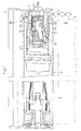
- a tubular winding roller 2 is rotatably supported at both ends by a support bracket 1.
- a plug 9 projects from a left side portion of the bracket 1.
- the left end of the winding roller 2 is supported on the periphery of the plug 9.
- a spring shaft 11 projects from a right side portion of the bracket 1.
- a pulley 3 is rotatably supported at the periphery of a base end of the spring shaft 11.
- the right end of the winding roller 2 is relatively rotatably supported through a clutch device 10 on the outer periphery of the pulley 3.
- An endless cord 4 is looped around the pulley 3.
- a screen 5 is attached to the winding roller 2 such that it may be wound thereabout.
- the screen 5 has a weight bar 6 at its lower end and a handle 7 at the center portion of its lower end.
- a torsion coil spring 8 is installed in the interior space of the left end of the winding roller 2.
- the torsion coil spring 8 provides the torque necessary to rotate the winding roller 2 when the screen 5 is lifted.
- the right end (not shown) of the torsion coil spring 8 is secured to the inner surface of the center portion of the winding roller 2, while the left end thereof is secured to the tip portion of the plug 9.
- a cylindrical sleeve 14 is relatively rotatably supported at the right end thereof around the outer periphery of the pulley 3.
- the sleeve 14 is positioned within the winding roller 2 and journaled about the spring shaft 11.
- the right end of the sleeve 14 is secured to the right end of the winding roller 2, while the left end of the sleeve 14 is coupled to a well-known governor 27 which frictionally engages the inner surface of the winding roller 2.
- the governor 27 is arranged to frictionally damp the rotary motion of the winding roller 2.
- a suitable governor design is set forth in Japanese Unexamined Published (Laid-Open) Patent Application No 63-171988, which is incorporated herein by reference.
- the shaft 11 is divided into three stepped portions having sequentially narrower diameters are from the base end to the tip end. That is, the shaft 11 includes an outer shaft portion 16, an intermediate shaft portion 17 and an inner shaft portion 18 with the outer shaft portion 16 having the largest diameter and the inner shaft portion 18 having the smallest diameter.
- the pulley 3, a first clutch drum 12 and a second clutch drum 13 are respectively rotatably journaled around the respective shaft portions 16, 17 and 18.
- the second clutch drum 13 includes a hexagonal connecting nut 13a.
- the sleeve 14 includes an intermediate support wall having a hexagonal recess 15 therein that closely receives the connecting nut 13a.
- the clutch sleeve 14 is integrally rotatable with the second clutch drum 13 with the axis of shaft 11 being located at its rotational center.
- the first clutch drum 12 includes cylindrical portions 12a and 12b whose outer diameters are equal to the diameter of the intermediate shaft portion 17.
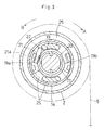
- a flange 19 is formed at an intermediate portion of the first clutch drum 12, and a pair of wings 19a and 19b are symmetrically formed with respect to the central axis of the clutch drum 12 in such a manner as to radially project from the flange 19.
- the brake spring 20 When a torque is applied to the first clutch drum 12 to move the screen 5 in the lowering direction A, the brake spring 20 is loosened to reduce frictional forces between the brake spring 20 and the first clutch drum 12 as well as between the brake spring 20 and the intermediate shaft portion 17. Thus, the first clutch drum 12 is permitted to rotate.
- the brake spring 20 when a torque is applied to the first clutch drum 12 to move the screen in the lifting direction B, the brake spring 20 is tightly wrapped around the first clutch drum 12 and the intermediate shaft portion 17. This increases the frictional forces between the spring 20 and the first clutch drum 12 and between the spring 20 and the intermediate shaft portion 17. In this condition, rotational movement of the first clutch drum 12 is prevented.
- a clutch arm 21 is pivotally supported by the wing 19a of first clutch drum 12. More specifically, a pin 21a positioned at an intermediate portion of a clutch arm 21 pivotally engages the underside of wing 19a.
- the clutch arm 21 has a disk-shaped engaging portion 22 at the base end thereof, and with a hole 24 at the tip portion thereof.
- the clutch arm 21 is secured to only the wing 19a, and is not secured to the wing 19b.
- the wing 19b is used only in cases where it is desirable to reverse the lifting and lowering operations of the roller blind.
- the pulley 3 has a pair of legs 25 that project axially towards the center of the roller.
- the legs 25 are positioned between the wings 19a and 19b of the drum 12.
- a first one of the legs 25 comes into contact with the wing 19a to apply a torque directed in the screen lowering direction A to the first clutch drum 12.
- the second one of the legs 25 pushes the engaging portion 22 of the clutch arm 21 to allow the clutch arm 21 to swing in a clockwise direction as seen in Fig. 1.
- the second clutch drum 13 includes a cylindrical portion 13b having the same outer diameter as the cylindrical portions 12a and 12b.
- the flange 19 has a plurality of notches 26 formed about its periphery.
- a first end 23a of the clutch spring 23 is secured to one of the notches 26, while the second end 23b of the clutch spring 23 is secured to the hole 24 in the clutch arm 21.
- the rotation of the first clutch drum 12 in the clockwise direction causes the brake spring 20 to be loosened, and the friction force between the first clutch drum 12 and the brake spring 20 is reduced.
- the clutch spring 23 remains tightly-coiled or wound around the first and second clutch drums 12 and 13. Accordingly, the torque of the first clutch drum 12 is transmitted through the clutch spring 23, the second clutch drum 13 and the clutch sleeve 14 to the winding roller 2, so that the winding roller 2 is rotated in the screen lowering direction A and the screen is lowered.
- the torque is also accumulated as an urging force in the torsion coil spring 8.
- the winding roller 2 When the user releases the cord 4 after the screen 5 has been lowered to a selected position, the winding roller 2 is rotatively urged in the screen lifting direction B by the urging force accumulated in the torsion coil spring 8. The torque of the winding roller 2 due to the urging force of the torsion coil spring 8 is transmitted through the clutch sleeve 14 to the second clutch drum 13. As a result, the clutch spring 23 is more tightly wound around the first and second clutch drums 12 and 13, and thus the frictional forces between the spring 23 and the first clutch drum 12 and between the spring 23 and the second clutch drum 13 are increased. The increase of the frictional force enables the torque supplied to the second clutch drum 13 to be transmitted to the first clutch drum 12.
- the torque supplied to the first clutch drum 12 serves to strengthen a tightly-wound action of the brake spring 20, thereby increasing the frictional forces between the brake spring 20 and the first clutch drum 12 and between the brake spring 20 and the shaft 11, so that the rotation of the first clutch drum 12 is stopped. Therefore, undesired continuous rotation of the winding roller 2 is prevented, and the screen 5 remains stable at the selected position.
- the pulley 3 When the screen 5 is lifted, the pulley 3 is slightly rotated in the opposite direction by operation of the cord 4. That is, in the screen lifting direction B as shown in Fig. 3.
- the rotation of the pulley 3 rotates the leg 25 located at the upper position as shown in Fig. 3 counterclockwise and pushes the engaging portion 22 of the clutch arm 21, so that the clutch arm 21 is swung in a clockwise direction as shown in Fig. 1.
- This loosens the clutch spring 23 which causes the frictional force between the clutch spring 23 and the second clutch drum 13 to be reduced.
- power transmission between the first and second clutch drums 12, 13 are cut off. That is, the second clutch drum 13 is freely rotatable relatively to the clutch spring 23.
- the screen 5 In a case where the screen 5 is lowered by the handle 7 of the weight bar 6, the torque acting on the winding roller 2 through the screen 5 is transmitted through the clutch sleeve 14 to the second clutch drum 13, and serves to reduce the frictional force between the second clutch drum 13 and the clutch spring 23. Therefore, the screen may be lowered by using the handle 7. In this case, the rotation of the winding roller 2 is not transmitted to the pulley 3.
- the winding roller 2 is easily rotated to lift the screen to the predetermined position.
- the screen lowering operation can be carried out by the operation of the cord or handle 7. Accordingly, the lifting and lowering operation of the screen 5 according to this invention is very simple.
Landscapes
- Engineering & Computer Science (AREA)
- General Engineering & Computer Science (AREA)
- Mechanical Engineering (AREA)
- Structural Engineering (AREA)
- Architecture (AREA)
- Civil Engineering (AREA)
- Operating, Guiding And Securing Of Roll- Type Closing Members (AREA)
Claims (5)
- Wickelvorrichtung zur Verwendung in einem Rolladen, der umfaßt:
eine Halteklammer (1), eine Wickelwalze (2), die drehbar von der Halteklammer (1) gehalten wird, einen Schirm (5), der an der Wickelwalze (2) derart angebracht ist, daß er auf der Walze enstprechend der Drehung der Wickelwalze auf- und abgewickelt werden kann, eine Rolle (3), die drehbar an der Halteklammer (1) angeordnet ist, eine Schnur (4), die um die Rolle (3) zu deren Verdrehung geführt ist, eine Drängeinrichtung, die mit der Wickelwalze so verbunden ist, daß sie die Wickelwalze in Schirmaufwickelrichtung drängt, wobei die Wickelwalze eine Innenbohrung besitzt und die Drängeinrichtung innerhalb der Innenbohrung der Wickelwalze angeordnet ist;
eine Welle (11), die die Rolle (3) trägt und von der Halteklammer gehalten wird;
eine Hülse (14), die relativ drehbar auf der Rolle gehalten ist und sich zusammen mit der Wickelwalze dreht,
dadurch gekennzeichnet, daß
eine Kupplungseinrichtung zwischen der Wickelwalze und der Rolle vorgesehen ist, welche Drehungen der Rolle auf die Wickelwalze überträgt, wobei die Kupplungseinrichtung umfaßt:
die Welle (11);
die Hülse (14);
eine Kupplungstrommel (12), die drehbar um die Welle innerhalb der Hülse gehalten ist;
eine Bremsfeder (20), die auf der Kupplungstrommel (12) und einem ersten Abschnitt der Welle (11) gelagert und in einem derartigen Sinn gewunden ist, daß eine Bewegung der Kupplungstrommel in der Schirmabwärtsrichtung zu einer Lockerung der Bremsfeder führt, die eine Drehbewegung der Kupplungstrommel (12) ermöglicht, und daß die Drehung der Kupplungstrommel in der Schirmaufwärtsrichtung zu einem Anziehen der Bremsfeder führt, das eine relative Drehbewegung der Kupplungstrommel und der Welle verhindert; und
eine Kupplungsfeder (23), die zwischen der Kupplungstrommel und einem zweiten Abschnitt der Welle vorgesehen ist und sich zwischen der Trommel und der Hülse erstreckt, wobei die Kupplungsfeder in einem derartigen Sinn gewunden ist, daß eine Bewegung der Rolle und der Kupplungstrommel in der Schirmabwärtsrichtung dazu führt, daß die Feder gespannt wird, wodurch die Kupplungstrommel und die Hülse verbunden werden und eine Kraftübertragung von der Kupplungstrommel zur Hülse ermöglicht wird, und daß eine Bewegung der Rolle und der Kupplungstrommel in der Schirmaufwärtsrichtung dazu führt, daß die Feder sich abwickelt, dadurch die Kupplungstrommel und die Hülse getrennt werden und somit die Kraftübertragung zwischen der Kupplungstrommel und der Hülse unterbrochen wird,
wobei die entgegengesetzt gerichteten Kräfte, die durch die Kupplungseinrichtung und die Drängeinrichtung ausgeübt werden, eine Drehung der Wickelwalze verhindern, wenn die Schnur nicht betätigt wird,
und wobei die Rolle (3) und die Kupplungstrommel (12) so positioniert sind, daß die Drehung der Rolle dazu führt, daß die Rolle mit der Kupplungstrommel in Eingriff steht und eine Übertragung der Drehung von der Rolle auf die Kupplungstrommel bewirkt, wobei die Rolle und die Kupplungstrommel derart relativ zueinander positioniert sind, daß ein vorbestimmter Drehwinkel der Rolle auftritt, bevor die Rolle mit der Kupplungstrommel in Eingriff kommt, wodurch sich die Rolle um einen vorbestimmten Winkel in Schirmaufwärtsrichtung drehen kann, wenn die Schnur zum Anheben des Schirms betätigt wird, wobei die Kupplungseinrichtung, nachdem die Rolle um den vorherbestimmten Winkel gedreht wurde, es möglich macht, daß die Drängeinrichtung die Wickelwalze in der Schirmaufwärtsrichtung dreht,
wodurch die Rolle sich frei um einen vorbestimmten Winkel in Schirmabwärtsrichtung bewegen kann, wenn die Schnur zum Absenken des Schirmes betätigt wird, und danach die Schirmabwärtsbewegung der Schnur über die Rolle zu der Wickelwalze übertragen wird, um den Schirm abzusenken. - Wickelvorrichtung nach Anspruch 1, die des weiteren eine zweite Trommel (13) umfaßt, die auf der Welle in Nachbarschaft zu der Kupplungstrommel (12) angeordnet ist, wobei die zweite Trommel (13) zusammen mit der Hülse (14) drehbar ist, und worin die Kupplungsfeder (23) sich zwischen der zweiten Trommel und der Kupplungstrommel erstreckt und auf dem Außenumfang der zweiten Trommel und der Kupplungstrommel gelagert ist.
- Wickelvorrichtung nach Anspruch 1, worin die Kupplungseinrichtung des weiteren umfaßt:
mindestens ein Schenkelpaar (25), das von der Rolle hervorragt;
mindestens einen Vorsprung (19a, 19b), der an dem Außenumfang der Kupplungstrommel angeordnet ist und der mit den Schenkeln entsprechend der Drehung der Rolle in Eingriff gebracht werden kann; und
einen Kupplungshebel (21), der drehbar von dem Vorsprung gehalten wird und einen ersten Endabschnitt (21a) besitzt, der mit der Kupplungsfeder verbunden ist, und einen zweiten Endabschnitt (22) besitzt, der mit den Schenkeln in Eingriff gebracht werden kann, und wobei
im Falle, daß die Schnur nicht betätigt wird, der erste Endabschnitt des Kupplungshebels auf die Kupplungsfeder wirkt und eine Kraftübertragung zwischen der Kupplungstrommel und der Hülse ermöglicht,
im Falle, daß die Rolle in Schirmabwärtsrichtung gedreht wird, die Drehung der Rolle über die Kupplungstrommel und die Kupplungsfeder auf die Hülse durch einen Eingriff zwischen den Schenkeln und dem Vorsprung der Kupplungstrommel übertragen wird, und
im Falle, daß die Rolle in Schirmaufwärtsrichtung gedreht wird, die Kraftübertragung zwischen der Rolle und der Hülse durch einen Eingriff zwischen den Schenkeln und dem zweiten Endabschnitt des Kupplungshebels und einer Verbindung zwischen dem zweiten Endabschnitt des Kupplungshebels und der Kupplungsfeder unterbrochen wird. - Wickelvorrichtung nach Anspruch 3, worin die Kupplungstrommel (12) ein Paar von Vorsprüngen (19a, 19b) umfaßt und der Vorsprung, der den Kupplungshebel hält, in Übereinstimmung mit der Handhabungsrichtung der Schnur während des Anhebens und Absenkens des Schirmes bestimmt wird.
- Wickelvorrichtung zur Verwendung in einem Rolladen, der umfaßt:
eine Halteklammer (1), eine Wickelwalze (2), die drehbar von der Halteklammer (1) gehalten wird, einen Schirm (5), der an der Wickelwalze (2) derart angebracht ist, daß er auf der Walze enstprechend der Drehung der Wickelwalze auf- und abgewickelt werden kann, eine Rolle (3), die drehbar an der Halteklammer (1) angeordnet ist, eine Schnur (4), die um die Rolle (3) zu deren Verdrehung geführt ist, eine Drängeinrichtung, die mit der Wickelwalze so verbunden ist, daß sie die Wickelwalze in Schirmaufwickelrichtung drängt, wobei die Wickelwalze eine Innenbohrung besitzt und die Drängeinrichtung innerhalb der Innenbohrung der Wickelwalze angeordnet ist;
eine Welle (11), die die Rolle (3) trägt und von der Halteklammer gehalten wird;
eine Hülse (14), die relativ drehbar auf der Rolle gehalten ist und sich zusammen mit der Wickelwalze dreht,
dadurch gekennzeichnet, daß
eine Kupplungseinrichtung zwischen der Wickelwalze und der Rolle vorgesehen ist, welche Drehungen der Rolle auf die Wickelwalze überträgt, wobei die Kupplungseinrichtung umfaßt:
die Welle (11);
die Hülse (14);
eine Kupplungstrommel (12), die drehbar um die Welle innerhalb der Hülse gehalten ist;
eine Bremsfeder (20), die auf der Kupplungstrommel (12) und einem ersten Abschnitt der Welle (11) gelagert und in einem derartigen Sinn gewunden ist, daß eine Bewegung der Kupplungstrommel in der Schirmabwärtsrichtung zu einer Lockerung der Bremsfeder führt, die eine Drehbewegung der Kupplungstrommel (12) ermöglicht, und daß die Drehung der Kupplungstrommel in der Schirmaufwärtsrichtung zu einem Anziehen der Bremsfeder führt, das eine relative Drehbewegung der Kupplungstrommel und der Welle verhindert; und
eine Kupplungsfeder (23), die zwischen der Kupplungstrommel und einem zweiten Abschnitt der Welle vorgesehen ist und sich zwischen der Trommel und der Hülse erstreckt, wobei die Kupplungsfeder in einem derartigen Sinn gewunden ist, daß eine Bewegung der Rolle und der Kupplungstrommel in der Schirmabwärtsrichtung dazu führt, daß die Feder gespannt wird, wodurch die Kupplungstrommel und die Hülse verbunden werden und eine Kraftübertragung von der Kupplungstrommel zur Hülse ermöglicht wird, und daß eine Bewegung der Rolle und der Kupplungstrommel in der Schirmaufwärtsrichtung dazu führt, daß die Feder sich abwickelt, dadurch die Kupplungstrommel und die Hülse getrennt werden und somit die Kraftübertragung zwischen der Kupplungstrommel und der Hülse unterbrochen wird,
wobei die entgegengesetzt gerichteten Kräfte, die durch die Kupplungseinrichtung und die Drängeinrichtung ausgeübt werden, eine Drehung der Wickelwalze verhindern, wenn die Schnur nicht betätigt wird,
und wobei die Rolle (3) und die Kupplungstrommel (12) so positioniert sind, daß die Drehung der Rolle dazu führt, daß die Rolle mit der Kupplungstrommel in Eingriff steht und eine Übertragung der Drehung von der Rolle auf die Kupplungstrommel bewirkt, wobei die Rolle und die Kupplungstrommel derart relativ zueinander positioniert sind, daß ein vorbestimmter Drehwinkel der Rolle auftritt, bevor die Rolle mit der Kupplungstrommel in Eingriff kommt, wodurch sich die Rolle um einen vorbestimmten Winkel in Schirmaufwärtsrichtung drehen kann, wenn die Schnur zum Anheben des Schirms betätigt wird, wobei die Kupplungseinrichtung, nachdem die Rolle um den vorherbestimmten Winkel gedreht wurde, es möglich macht, daß die Drängeinrichtung die Wickelwalze in der Schirmaufwärtsrichtung dreht,
wodurch die Rolle sich frei um einen vorbestimmten Winkel in Schirmabwärtsrichtung bewegen kann, wenn die Schnur zum Absenken des Schirmes betätigt wird, und danach die Schirmabwärtsbewegung der Schnur über die Rolle zu der Wickelwalze übertragen wird, um den Schirm abzusenken,
mindestens ein Schenkelpaar (25), das von der Rolle hervorragt;
mindestens einen Vorsprung (19a, 19b), der an dem Außenumfang der Kupplungstrommel angeordnet ist und der mit den Schenkeln entsprechend der Drehung der Rolle in Eingriff gebracht werden kann; und
einen Kupplungshebel (21), der drehbar von dem Vorsprung gehalten wird und einen ersten Endabschnitt (21a) besitzt, der mit der Kupplungsfeder verbunden ist, und einen zweiten Endabschnitt (22) besitzt, der mit den Schenkeln in Eingriff gebracht werden kann, und wobei
im Falle, daß die Schnur nicht betätigt wird, der erste Endabschnitt des Kupplungshebels auf die Kupplungsfeder wirkt und eine Kraftübertragung zwischen der Kupplungstrommel und der Hülse ermöglicht,
im Falle, daß die Rolle in Schirmabwärtsrichtung gedreht wird, die Drehung der Rolle über die Kupplungstrommel und die Kupplungsfeder auf die Hülse durch einen Eingriff zwischen den Schenkeln und dem Vorsprung der Kupplungstrommel übertragen wird, und
im Falle, daß die Rolle in Schirmaufwärtsrichtung gedreht wird, die Kraftübertragung zwischen der Rolle und der Hülse durch einen Eingriff zwischen den Schenkeln und dem zweiten Endabschnitt des Kupplungshebels und einer Verbindung zwischen dem zweiten Endabschnitt des Kupplungshebels und der Kupplungsfeder unterbrochen wird.
Applications Claiming Priority (2)
| Application Number | Priority Date | Filing Date | Title |
|---|---|---|---|
| JP274117/90 | 1990-10-13 | ||
| JP2274117A JP2656147B2 (ja) | 1990-10-13 | 1990-10-13 | ロールブラインドのスクリーン昇降装置 |
Publications (2)
| Publication Number | Publication Date |
|---|---|
| EP0481688A1 EP0481688A1 (de) | 1992-04-22 |
| EP0481688B1 true EP0481688B1 (de) | 1995-02-15 |
Family
ID=17537255
Family Applications (1)
| Application Number | Title | Priority Date | Filing Date |
|---|---|---|---|
| EP91309360A Expired - Lifetime EP0481688B1 (de) | 1990-10-13 | 1991-10-10 | Aufrolleinrichtung für Rolläden |
Country Status (4)
| Country | Link |
|---|---|
| US (1) | US5167269A (de) |
| EP (1) | EP0481688B1 (de) |
| JP (1) | JP2656147B2 (de) |
| DE (1) | DE69107399T2 (de) |
Families Citing this family (44)
| Publication number | Priority date | Publication date | Assignee | Title |
|---|---|---|---|---|
| JPH06212867A (ja) * | 1992-11-30 | 1994-08-02 | Toso Co Ltd | コード操作可能なロールブラインド |
| US5375643A (en) * | 1992-12-22 | 1994-12-27 | General Clutch Corporation | Spring clutch assembly with reduced radial bearing forces |
| JP3282981B2 (ja) * | 1996-12-18 | 2002-05-20 | 立川ブラインド工業株式会社 | 連装型ロールブラインドのスクリーン昇降装置 |
| US5791393A (en) * | 1997-03-31 | 1998-08-11 | Judkins; Ren | Shade operator |
| US5887637A (en) * | 1997-05-05 | 1999-03-30 | Phyper; Duncan | Aperture covering system |
| WO1999004126A1 (en) * | 1997-07-16 | 1999-01-28 | A/S Chr. Fabers Fabriker | Winding mechanism for roller blinds |
| US5938139A (en) * | 1997-11-05 | 1999-08-17 | Lin; Cheng-Tai | Manually operated screen reeling device |
| US5927370A (en) * | 1997-11-18 | 1999-07-27 | Judkins; Ren | Release brake shade operator |
| JP3524738B2 (ja) * | 1997-11-27 | 2004-05-10 | 株式会社ニチベイ | ロールスクリーン |
| IT244838Y1 (it) * | 1998-03-12 | 2002-03-14 | Gaposa Srl | Motoriduttore tubolare per la movimentazione di tapparelle e tendeavvolgibili |
| CA2277603C (en) * | 1998-07-15 | 2007-01-09 | Konrad Welfonder | A winding and unwinding mechanism for blinds and or shades |
| CA2270682C (en) * | 1999-05-04 | 2007-08-14 | Sunproject Canada Inc. | Mechanism for locking roll up curtains and the like |
| US6142211A (en) * | 1999-08-10 | 2000-11-07 | Judkins; Ren | Shade operator with release brake |
| US7380582B1 (en) * | 2003-04-09 | 2008-06-03 | Hunter Douglas Inc. | Mounting arrangement for coverings for architectural openings |
| US6941996B2 (en) * | 2003-05-21 | 2005-09-13 | Springs Window Fashions Lp | Double shade with modular end caps and method of assembling same |
| TW200503651A (en) * | 2003-07-18 | 2005-02-01 | Fu-Mei Fun | Buffer device for roller blinds |
| GB2392946B (en) | 2003-08-19 | 2004-07-21 | Louver Lite Ltd | Improvements in control units |
| JP4440802B2 (ja) * | 2005-02-28 | 2010-03-24 | 株式会社ニチベイ | ブラインド |
| DE102005014173B4 (de) * | 2005-03-29 | 2010-11-11 | Webasto Ag | Rolloanordnung, insbesondere Laderaumabdeckung für den Laderaum eines Fahrzeugs, mit Endlagendämpfung |
| US8511364B2 (en) * | 2006-01-13 | 2013-08-20 | Hunter Douglas Inc. | Spring motor for drive for coverings for architectural openings |
| US7740045B2 (en) * | 2006-10-25 | 2010-06-22 | Hunter Douglas Inc. | Spring motor and drag brake for drive for coverings for architectural openings |
| KR100658640B1 (ko) * | 2006-02-06 | 2006-12-19 | 곽재석 | 롤 스크린의 자동 승강 구동장치 |
| US20080067274A1 (en) * | 2006-09-18 | 2008-03-20 | Cannaverde Joseph A | Window treatment system with a single cord |
| US8752607B2 (en) | 2007-10-22 | 2014-06-17 | Hunter Douglas Inc. | Covering for architectural openings including a rotation limiter |
| US20080230191A1 (en) * | 2007-01-12 | 2008-09-25 | Philip Ng | Roller Clutch Assembly |
| US7730689B2 (en) * | 2007-01-30 | 2010-06-08 | Carmen L. Figueroa-Morales | Window arrangement to aid in the reduction of unwanted air movement in or out of windows |
| US20090120592A1 (en) * | 2007-11-14 | 2009-05-14 | Hunter Douglas Inc. | Control unit for lift system for coverings for architectural openings |
| US8307878B2 (en) | 2009-01-14 | 2012-11-13 | Hunter Douglas Inc. | Noise dampening motor drive system for retractable covering for architectural openings |
| MX2011008144A (es) | 2009-02-09 | 2011-09-06 | Hunter Douglas Ind Bv | Sistema de resorte para persianas enrolladas. |
| GB0914161D0 (en) * | 2009-08-13 | 2009-09-16 | Turnils Uk Ltd | Locking system for blinds |
| SG184514A1 (en) * | 2010-04-12 | 2012-11-29 | Tachikawa Blind Mfg | Operation apparatus of sunlight shielding apparatus, lifting apparatus of roll-up blind and operation pulley |
| KR102001125B1 (ko) | 2010-12-30 | 2019-07-17 | 헌터더글라스인코포레이티드 | 건축물 개구부용 절첩가능 차양막들을 위한 작동 끈 시스템 |
| NL1039407C2 (en) | 2012-02-27 | 2013-08-28 | Hunter Douglas Ind Bv | Architectural covering having a drive mechanism for extending and retracting a covering member between opposite first and second end positions. |
| TWM440739U (en) * | 2012-04-06 | 2012-11-11 | zhe-wen Zhou | Controller for roller curtain |
| AU2015346452B2 (en) | 2014-11-10 | 2020-08-13 | Hunter Douglas Inc. | Covering for an architectural opening including multiple stage spring assembly |
| TWI564468B (zh) * | 2014-11-17 | 2017-01-01 | 德侑股份有限公司 | 窗簾及其致動系統 |
| US20160222722A1 (en) * | 2015-02-03 | 2016-08-04 | Newell Window Furnishings, Inc. | Window covering and operating system |
| US9702187B2 (en) * | 2015-02-13 | 2017-07-11 | Hunter Douglas Inc. | Covering for an architectural opening having nested tubes |
| US9593530B1 (en) * | 2015-08-18 | 2017-03-14 | Hunter Douglas Inc. | Brake assembly for a covering for an architectural opening |
| CN205605050U (zh) * | 2016-01-22 | 2016-09-28 | 亿丰综合工业股份有限公司 | 窗帘的阻尼装置 |
| CN205532187U (zh) * | 2016-01-29 | 2016-08-31 | 亿丰综合工业股份有限公司 | 窗帘升降控制结构 |
| GB201708009D0 (en) * | 2017-05-18 | 2017-07-05 | Day Perry | Spring-operated roller blind |
| US10415306B2 (en) * | 2017-07-05 | 2019-09-17 | Whole Space Industries Ltd | Window covering and stability mechanism for the same |
| WO2021183395A1 (en) * | 2020-03-09 | 2021-09-16 | Teh Yor Co., Ltd. | Window shade and actuating system thereof |
Family Cites Families (13)
| Publication number | Priority date | Publication date | Assignee | Title |
|---|---|---|---|---|
| GB238426A (en) * | 1924-11-19 | 1925-08-20 | Reginald Harold Tutty | An internal check action to a spring blind roller |
| JPS57114095U (de) * | 1981-01-08 | 1982-07-14 | ||
| DE3232722A1 (de) * | 1982-09-03 | 1984-03-15 | Zündwarenfabrik Starcke GmbH & Co, 4520 Melle | Seitenzug-rollo |
| US4834164A (en) * | 1982-11-22 | 1989-05-30 | Lynmour, Ltd. | Window shade roller brackets and assembly including the same |
| GB2151678B (en) * | 1983-12-20 | 1987-10-21 | Raymond Peter Allen Brock | Roller blind |
| JPS61102988A (ja) * | 1984-10-27 | 1986-05-21 | ト−ソ−株式会社 | コ−ド操作式ロ−ルブラインド |
| DE3536160A1 (de) * | 1985-10-10 | 1987-04-23 | Starcke Zuendwarenfab | Seitenzugrollo |
| JPS63106894A (ja) * | 1986-10-24 | 1988-05-11 | オムロン株式会社 | 取引処理装置 |
| IT208635Z2 (it) * | 1986-12-17 | 1988-05-28 | Mottura Spa | Tenda a rullo con freno a masse centrifughe disposto all esterno del rullo e sopporto d estremita includente tale freno |
| JPH0613825B2 (ja) * | 1987-01-09 | 1994-02-23 | 立川ブラインド工業株式会社 | ロ−ルブラインドの昇降装置 |
| US4779662A (en) * | 1987-04-24 | 1988-10-25 | Heli-X Shade Corporation | Shade operator |
| US4865109A (en) * | 1987-11-30 | 1989-09-12 | Sherman Roger W | Apparatus for opening and closing a window shade or the like |
| IT1223746B (it) * | 1988-08-01 | 1990-09-29 | Mottura Spa | Tenda a rullo con dispositivo di arresto a camma cilindrica |
-
1990
- 1990-10-13 JP JP2274117A patent/JP2656147B2/ja not_active Expired - Fee Related
-
1991
- 1991-10-08 US US07/772,950 patent/US5167269A/en not_active Expired - Fee Related
- 1991-10-10 EP EP91309360A patent/EP0481688B1/de not_active Expired - Lifetime
- 1991-10-10 DE DE69107399T patent/DE69107399T2/de not_active Expired - Fee Related
Also Published As
| Publication number | Publication date |
|---|---|
| JP2656147B2 (ja) | 1997-09-24 |
| DE69107399T2 (de) | 1995-06-08 |
| JPH04149390A (ja) | 1992-05-22 |
| EP0481688A1 (de) | 1992-04-22 |
| US5167269A (en) | 1992-12-01 |
| DE69107399D1 (de) | 1995-03-23 |
Similar Documents
| Publication | Publication Date | Title |
|---|---|---|
| EP0481688B1 (de) | Aufrolleinrichtung für Rolläden | |
| JP2774383B2 (ja) | ローラー式シェード用制御器 | |
| US4697630A (en) | Tilt mechanism for venetian blinds | |
| EP0056088B1 (de) | Vorrichtung zur Betätigung des Vorhanges an einem Rollvorhang | |
| JPH0119032B2 (de) | ||
| AU722791B2 (en) | Belt hoists | |
| JP3570926B2 (ja) | ロールブラインドの昇降装置 | |
| US4151981A (en) | Brake drum controlled hoist | |
| EP0717166B1 (de) | Trage- und Steuervorrichtung für ein Rollo | |
| US6561448B2 (en) | Convertible chassis fishing reel | |
| CA2209628C (en) | Belt hoist | |
| CA1142497A (en) | Fishing reel | |
| AU601885B2 (en) | Cable reel | |
| JP2006233418A (ja) | 操作コード式回転軸制御クラッチ機構 | |
| EP0180832B1 (de) | Sperrvorrichtung für Rollvorhänge | |
| JP3219260B2 (ja) | ロールスクリーン装置 | |
| JPS60156892A (ja) | カ−テンとロ−ラブラインド作動用エネルギ回復型ウインチ | |
| JP2500941Y2 (ja) | ドラムリ―ルのブレ―キ装置 | |
| KR100415894B1 (ko) | 오버헤드 도어의 와이어 이탈방지장치 | |
| JPS636809Y2 (de) | ||
| JPS6354633B2 (de) | ||
| JP2860230B2 (ja) | ロールスクリーン装置 | |
| CA2415872C (en) | Convertible chassis fishing reel | |
| KR0133435Y1 (ko) | 낚시용 스피닝릴의 레버식 제동장치 | |
| JPH0335838Y2 (de) |
Legal Events
| Date | Code | Title | Description |
|---|---|---|---|
| PUAI | Public reference made under article 153(3) epc to a published international application that has entered the european phase |
Free format text: ORIGINAL CODE: 0009012 |
|
| AK | Designated contracting states |
Kind code of ref document: A1 Designated state(s): CH DE FR GB IT LI |
|
| 17P | Request for examination filed |
Effective date: 19920713 |
|
| 17Q | First examination report despatched |
Effective date: 19930921 |
|
| ITF | It: translation for a ep patent filed |
Owner name: DE DOMINICIS & MAYER S.R.L. |
|
| GRAA | (expected) grant |
Free format text: ORIGINAL CODE: 0009210 |
|
| AK | Designated contracting states |
Kind code of ref document: B1 Designated state(s): CH DE FR GB IT LI |
|
| REF | Corresponds to: |
Ref document number: 69107399 Country of ref document: DE Date of ref document: 19950323 |
|
| ET | Fr: translation filed | ||
| PLBE | No opposition filed within time limit |
Free format text: ORIGINAL CODE: 0009261 |
|
| STAA | Information on the status of an ep patent application or granted ep patent |
Free format text: STATUS: NO OPPOSITION FILED WITHIN TIME LIMIT |
|
| 26N | No opposition filed | ||
| REG | Reference to a national code |
Ref country code: GB Ref legal event code: IF02 |
|
| PGFP | Annual fee paid to national office [announced via postgrant information from national office to epo] |
Ref country code: FR Payment date: 20021008 Year of fee payment: 12 |
|
| PGFP | Annual fee paid to national office [announced via postgrant information from national office to epo] |
Ref country code: GB Payment date: 20021009 Year of fee payment: 12 |
|
| PGFP | Annual fee paid to national office [announced via postgrant information from national office to epo] |
Ref country code: DE Payment date: 20021011 Year of fee payment: 12 |
|
| PGFP | Annual fee paid to national office [announced via postgrant information from national office to epo] |
Ref country code: CH Payment date: 20021016 Year of fee payment: 12 |
|
| PG25 | Lapsed in a contracting state [announced via postgrant information from national office to epo] |
Ref country code: GB Free format text: LAPSE BECAUSE OF NON-PAYMENT OF DUE FEES Effective date: 20031010 |
|
| PG25 | Lapsed in a contracting state [announced via postgrant information from national office to epo] |
Ref country code: LI Free format text: LAPSE BECAUSE OF NON-PAYMENT OF DUE FEES Effective date: 20031031 Ref country code: CH Free format text: LAPSE BECAUSE OF NON-PAYMENT OF DUE FEES Effective date: 20031031 |
|
| PG25 | Lapsed in a contracting state [announced via postgrant information from national office to epo] |
Ref country code: DE Free format text: LAPSE BECAUSE OF NON-PAYMENT OF DUE FEES Effective date: 20040501 |
|
| GBPC | Gb: european patent ceased through non-payment of renewal fee |
Effective date: 20031010 |
|
| REG | Reference to a national code |
Ref country code: CH Ref legal event code: PL |
|
| PG25 | Lapsed in a contracting state [announced via postgrant information from national office to epo] |
Ref country code: FR Free format text: LAPSE BECAUSE OF NON-PAYMENT OF DUE FEES Effective date: 20040630 |
|
| REG | Reference to a national code |
Ref country code: FR Ref legal event code: ST |
|
| PG25 | Lapsed in a contracting state [announced via postgrant information from national office to epo] |
Ref country code: IT Free format text: LAPSE BECAUSE OF NON-PAYMENT OF DUE FEES;WARNING: LAPSES OF ITALIAN PATENTS WITH EFFECTIVE DATE BEFORE 2007 MAY HAVE OCCURRED AT ANY TIME BEFORE 2007. THE CORRECT EFFECTIVE DATE MAY BE DIFFERENT FROM THE ONE RECORDED. Effective date: 20051010 |