EP0717166B1 - Trage- und Steuervorrichtung für ein Rollo - Google Patents
Trage- und Steuervorrichtung für ein Rollo Download PDFInfo
- Publication number
- EP0717166B1 EP0717166B1 EP95830514A EP95830514A EP0717166B1 EP 0717166 B1 EP0717166 B1 EP 0717166B1 EP 95830514 A EP95830514 A EP 95830514A EP 95830514 A EP95830514 A EP 95830514A EP 0717166 B1 EP0717166 B1 EP 0717166B1
- Authority
- EP
- European Patent Office
- Prior art keywords
- roller
- tubular body
- blind
- web
- coupling
- Prior art date
- Legal status (The legal status is an assumption and is not a legal conclusion. Google has not performed a legal analysis and makes no representation as to the accuracy of the status listed.)
- Expired - Lifetime
Links
- 230000008878 coupling Effects 0.000 claims description 18
- 238000010168 coupling process Methods 0.000 claims description 18
- 238000005859 coupling reaction Methods 0.000 claims description 18
- 238000004804 winding Methods 0.000 claims description 15
- 230000000750 progressive effect Effects 0.000 abstract description 2
- 239000000463 material Substances 0.000 description 10
- 238000004873 anchoring Methods 0.000 description 1
- 239000002184 metal Substances 0.000 description 1
- 230000002093 peripheral effect Effects 0.000 description 1
- 230000000717 retained effect Effects 0.000 description 1
- 238000007789 sealing Methods 0.000 description 1
Images


Classifications
-
- E—FIXED CONSTRUCTIONS
- E06—DOORS, WINDOWS, SHUTTERS, OR ROLLER BLINDS IN GENERAL; LADDERS
- E06B—FIXED OR MOVABLE CLOSURES FOR OPENINGS IN BUILDINGS, VEHICLES, FENCES OR LIKE ENCLOSURES IN GENERAL, e.g. DOORS, WINDOWS, BLINDS, GATES
- E06B9/00—Screening or protective devices for wall or similar openings, with or without operating or securing mechanisms; Closures of similar construction
- E06B9/56—Operating, guiding or securing devices or arrangements for roll-type closures; Spring drums; Tape drums; Counterweighting arrangements therefor
- E06B9/80—Safety measures against dropping or unauthorised opening; Braking or immobilising devices; Devices for limiting unrolling
- E06B9/82—Safety measures against dropping or unauthorised opening; Braking or immobilising devices; Devices for limiting unrolling automatic
- E06B9/90—Safety measures against dropping or unauthorised opening; Braking or immobilising devices; Devices for limiting unrolling automatic for immobilising the closure member in various chosen positions
-
- E—FIXED CONSTRUCTIONS
- E06—DOORS, WINDOWS, SHUTTERS, OR ROLLER BLINDS IN GENERAL; LADDERS
- E06B—FIXED OR MOVABLE CLOSURES FOR OPENINGS IN BUILDINGS, VEHICLES, FENCES OR LIKE ENCLOSURES IN GENERAL, e.g. DOORS, WINDOWS, BLINDS, GATES
- E06B9/00—Screening or protective devices for wall or similar openings, with or without operating or securing mechanisms; Closures of similar construction
- E06B9/24—Screens or other constructions affording protection against light, especially against sunshine; Similar screens for privacy or appearance; Slat blinds
- E06B9/40—Roller blinds
-
- E—FIXED CONSTRUCTIONS
- E06—DOORS, WINDOWS, SHUTTERS, OR ROLLER BLINDS IN GENERAL; LADDERS
- E06B—FIXED OR MOVABLE CLOSURES FOR OPENINGS IN BUILDINGS, VEHICLES, FENCES OR LIKE ENCLOSURES IN GENERAL, e.g. DOORS, WINDOWS, BLINDS, GATES
- E06B9/00—Screening or protective devices for wall or similar openings, with or without operating or securing mechanisms; Closures of similar construction
- E06B9/24—Screens or other constructions affording protection against light, especially against sunshine; Similar screens for privacy or appearance; Slat blinds
- E06B9/40—Roller blinds
- E06B9/42—Parts or details of roller blinds, e.g. suspension devices, blind boxes
- E06B9/50—Bearings specially adapted therefor
-
- E—FIXED CONSTRUCTIONS
- E06—DOORS, WINDOWS, SHUTTERS, OR ROLLER BLINDS IN GENERAL; LADDERS
- E06B—FIXED OR MOVABLE CLOSURES FOR OPENINGS IN BUILDINGS, VEHICLES, FENCES OR LIKE ENCLOSURES IN GENERAL, e.g. DOORS, WINDOWS, BLINDS, GATES
- E06B9/00—Screening or protective devices for wall or similar openings, with or without operating or securing mechanisms; Closures of similar construction
- E06B9/56—Operating, guiding or securing devices or arrangements for roll-type closures; Spring drums; Tape drums; Counterweighting arrangements therefor
- E06B9/78—Operating, guiding or securing devices or arrangements for roll-type closures; Spring drums; Tape drums; Counterweighting arrangements therefor for direct manual operation, e.g. by tassels, by handles
-
- E—FIXED CONSTRUCTIONS
- E06—DOORS, WINDOWS, SHUTTERS, OR ROLLER BLINDS IN GENERAL; LADDERS
- E06B—FIXED OR MOVABLE CLOSURES FOR OPENINGS IN BUILDINGS, VEHICLES, FENCES OR LIKE ENCLOSURES IN GENERAL, e.g. DOORS, WINDOWS, BLINDS, GATES
- E06B9/00—Screening or protective devices for wall or similar openings, with or without operating or securing mechanisms; Closures of similar construction
- E06B9/56—Operating, guiding or securing devices or arrangements for roll-type closures; Spring drums; Tape drums; Counterweighting arrangements therefor
- E06B9/80—Safety measures against dropping or unauthorised opening; Braking or immobilising devices; Devices for limiting unrolling
- E06B2009/807—Brakes preventing fast screen movement
-
- E—FIXED CONSTRUCTIONS
- E06—DOORS, WINDOWS, SHUTTERS, OR ROLLER BLINDS IN GENERAL; LADDERS
- E06B—FIXED OR MOVABLE CLOSURES FOR OPENINGS IN BUILDINGS, VEHICLES, FENCES OR LIKE ENCLOSURES IN GENERAL, e.g. DOORS, WINDOWS, BLINDS, GATES
- E06B9/00—Screening or protective devices for wall or similar openings, with or without operating or securing mechanisms; Closures of similar construction
- E06B9/56—Operating, guiding or securing devices or arrangements for roll-type closures; Spring drums; Tape drums; Counterweighting arrangements therefor
- E06B9/80—Safety measures against dropping or unauthorised opening; Braking or immobilising devices; Devices for limiting unrolling
- E06B9/82—Safety measures against dropping or unauthorised opening; Braking or immobilising devices; Devices for limiting unrolling automatic
- E06B9/90—Safety measures against dropping or unauthorised opening; Braking or immobilising devices; Devices for limiting unrolling automatic for immobilising the closure member in various chosen positions
- E06B2009/905—Safety measures against dropping or unauthorised opening; Braking or immobilising devices; Devices for limiting unrolling automatic for immobilising the closure member in various chosen positions using wrap spring clutches
Definitions
- the present invention relates to devices for supporting and controlling roller blinds.
- Such a device is for instance known from EP-A-0 093 289.
- the object of the present invention is that of providing a device of the above indicated type which is relatively simple and reliable while enabling the user to control lowering and raising of the blind with easy and rapid operations.
- the invention provides a device for supporting and controlling a roller blind, having the features indicated in the annexed claim 1.
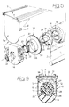
- reference numeral 1 generally designates a roller blind comprising a blind web 2 having a lower edge strengthened by a bar 3 and an upper edge (not visible in the drawings) anchored to a roller 4 for winding the web which is rotatably supported around a horizontal axis 5 by a fixed support structure 6 (figure 1).
- the fixed support structure 6 includes a metal profile 7 (see for example figures 4, 5) which is to be anchored by any known fixing means to a ceiling 8 or a wall, for example above a window aperture which blind 1 is to cover.
- roller 4 has a tubular body which, at its end facing towards head 9 (the end on the left in figure 1) which rotatably supports a disk 18 at its inside which is connected to the conventional spring which biasses the roller towards the position of complete winding of web 2.
- This spring is not shown in the annexed drawings, since it may be made in any known type and it does not fall, taken alone, within the scope of the present invention.
- the roller 4 rotates (in an anticlockwise direction with reference to figures 5, 9) causing the loading of said spring, which therefore is able to return the web to its raised position when it is no longer locked in a lowered condition.
- the knob 33 serves for adjusting the load of the return spring means of roller 4.
- tab 19 connected to the return spring located inside roller 4 is kept in a fixed position with respect to the end head 9.
- this rotation cannot be followed by disk 18 and tab 19, since the latter is rotatably connected to disk 21 and disk 21 cannot rotate since abutment surface 27 impinges against the end tail 31 of spring 29 which is tightened around the edge 28 of body 14 (fixed) and therefore prevents a rotation of disk 21.
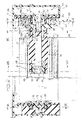
- the first tubular body 36 is rotatably supported around axis 5, in a way which will become apparent in the following, on a second fixed tubular body 38 (figures 2, 4) forming part of the end head 10 of the fixed support structure 6. More precisely, the first tubular body 36 is rotatably mounted on the second tubular body 38 with the interposition of a third tubular body 39 (figures 2, 4), which will be illustrated in detail in the following.
- Shaft 43 is received into an hexagonal cavity 44 (figure 2) formed at one end of a shaft 45 (figures 2, 4) which is freely rotatably mounted within the tubular body 36 and at its opposite end has two deflectable tapered axial wings 46 to receive and lock by a snap action a bush 47 thereon which is received inside the end of the tubular body 36 facing towards the inside of blind roller 4.
- Bush 47 is normally tightened within the coils of a helical spring coupling 48 having a radial end tail 49 received in a longitudinal slot 50 (figures 2, 4) of the tubular body 36.
- the coupling 48 is for connecting the centrifugal mass brake 41 to the blind roller when the latter is returned by its return spring means towards the raised position of web 2 and to discontinue this connection when the web is lowered, so as to avoid that brake 41 renders this operation more difficult.
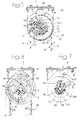
- roller 4 rotates in an anticlockwise direction (with reference to figures 3, 4 and 6-8).
- the slot 50 of tubular body 36 actuates the end tail 49 of spring 48 so as to open the coils of the latter to cause a free rotation thereon around bush 47. Therefore, in this condition, the rotation of the roller is not transmitted to the centrifugal mass brake.
- the roller is caused to rotate in the opposite direction (i.e.
- the fixed tubular body 38 forms part of a plate 65 of plastic material which is fixed to the housing 40 by a snap action as well as with the aid of a screw 66 (figure 2).
- a driving pulley 67 (figure 4) which is rotatably mounted on the tubular body 39 (figure 2) and can be engaged by a flexible driving member 68, which in the illustrated example is formed by a chain of balls 69 adapted to engage seats 70 formed on the periphery of pulley 67.
- the ball chain 68 has two vertical runs 71, 72 which extend sufficiently downwardly to enable the user to operate the blind easily; these runs are to be pulled downwardly to cause the progressive lowering or the rapid raising of the blind web 2 respectively.
- the driving pulley 67 has an inner radial tooth 73 which is arranged (figure 6) between the radial tail 61 of spring 60 and the end 58b of the rocking lever 58.
- the ends 58b and 58a of the rocking lever are for cooperation with the radial tooth 73 of the driving pulley 67 and the tail 64 of spring 62 respectively in order that when the run 72 of chain 68 is pulled, in order to cause the rapid raising of the blind web 2, the tooth 73 rotates the rocking lever 58 so as to cause an opening of spring 62.
- tubular body 39 The rotation of tubular body 39 is on its turn transmitted by the axial wing 59 to the tail 63 of spring 62 (figures 4 and 7) which is tightened around the portion 36a of the tubular body 36 and therefore transmits its rotation to said tubular body and consequently to the blind roller 4.
- the roller is caused to rotate in an anticlockwise direction, with reference to figures 6-8, causing thereby the lowering of the web 2 of the blind.
- the blind Once the blind has been locked in any partially or completely lowered position, it may be unlocked to cause a rapid return of web 2 to the raised condition by pulling the run 72 of chain 68. A short pulling action imparted to this run is sufficient to cause the engagement of the tooth 73, as already discussed, against the end 58b of the rocking lever 58. This rocking lever is thus compelled to rotate so as to bring its opposite end 58a against the tail 64 of spring 62 which is thus opened discontinuing the rigid connection between the tubular body 36 (connected to the blind roller) and the tubular body 39 (locked by spring 60 on the fixed tubular body 38). The tubular body 36 is therefore free to rotate inside the coils of spring 62, along with roller 4, under the action of the return spring means of the latter. In this manner, the web 2 is rapidly wound on roller 4.
- the slot 50 causes an opening of the coils of spring 48 so as to discontinue the connection between the centrifugal mass brake 41 and the blind roller.
- the tubular body 36 rotates in the direction tending to tighten the coils of spring 48 over the push 47. Therefore, in this condition, roller 4 is connected in rotation to the centrifugal mass brake 41, that slows down the roller during the winding stage.
- the device according to the invention enables the user to control the blind with very simple, convenient and rapid operations.
- it has a relatively simple and reliable structure.
- the possibility to adjust the load of the return spring means for the roller provided by the device illustrated in figure 5 renders the invention further advantageous.
- the possibility to snap engage the body 14 into the housing 10 following its coupling with roller 4 renders the assembling operation of the blind particularly simple.
Landscapes
- Engineering & Computer Science (AREA)
- Structural Engineering (AREA)
- Architecture (AREA)
- Civil Engineering (AREA)
- Advancing Webs (AREA)
- Operating, Guiding And Securing Of Roll- Type Closing Members (AREA)
- Registering, Tensioning, Guiding Webs, And Rollers Therefor (AREA)
- Rolls And Other Rotary Bodies (AREA)
Claims (3)
- Trage- und Steuervorrichtung für ein Rollo (1) dadurch gekennzeichnet, daß sie folgendes in Kombination aufweist:- einen Träger (6), der an einer Decke (8) oder einer Wand befestigt wird,- eine Rollowalze (4), auf die eine Rollobahn (2) aufgerollt ist und die drehbar um eine horizontale Achse (5) durch den Träger (6) gelagert ist, wobei die Walze (4) mit Federmitteln versehen ist, die die Walze in eine Ruhestellung vorspannen, bei der die Rollobahn (2) vollständig auf dieser aufgerollt ist,- eine Schwungkraftbremse (41), die in dem Träger (6) enthalten ist und bei Drehung mit einem Ende der Walze (4) des Rollos (1) verbunden ist, um die Drehung der Walze zu verlangsamen, wenn diese durch die Federmittel in ihre Ruhestellung zurückgeführt wird,- wobei die Vorrichtung ferner dadurch gekennzeichnet ist, daß:a) ein Ende der Rollowalze (4) bei Drehung fest mit einem ersten röhrenförmigen Körper (36) verbunden ist,b) der erste röhrenförmige Körper (36) mit der Schwungkraftbremse (41) unter Zwischenschaltung einer ersten Einwegschraubenfederkupplung (48) verbunden ist, die die Verbindung nur herstellt, wenn die Walze (4) sich in die Richtung zum Aufrollen der Rollobahn (2) dreht,c) der erste röhrenförmige Körper (36) drehbar in bezug auf einen zweiten feststehenden röhrenförmigen Körper (38), der einen Teil des Trägers (6) bildet, unter Zwischenschaltung der zweiten Einwegschraubenfederkupplung (60) angebracht ist, welche den ersten röhrenförmigen Körper (36) mit dem zweiten feststehenden röhrenförmigen Körper (38) verriegelt, wenn die Walze (4) sich in die Richtung zum Aufrollen der Rollobahn drehen will, um so diese in jeder beliebigen Position, zu der sie heruntergelassen wurde, zu fixieren,d) auf dem Träger (6) eine Antriebsscheibe (7) für das Rollo drehbar angebracht ist, die mit einem Steuerteil (68), beispielsweise einem flexiblen Steuerteil wie einer Kugelkette oder dergleichen, in Eingriff steht, wobei die Antriebsscheibe (67) wenigstens einen Innenzahn (73) aufweist, der in der Lage ist, die zweite Kupplung (60) zu entriegeln und die Drehung der Scheibe (67) auf die Walze (4) des Rollos zu übertragen, wenn die Scheibe (67) zur Drehung in Richtung zum Herunterlassen des Rollos (2) angetrieben wird,e) zwischen dem ersten röhrenförmigen Körper (36) und der zweiten Kupplung (60) ein dritter röhrenförmiger Körper (39) zwischengeschaltet ist, der sowohl mit dem zweiten röhrenförmigen Körper (38) mittels der zweiten Kupplung (60) als auch mit dem ersten röhrenförmigen Körper (36) mittels einer dritten Schraubenfederkupplung (62) verbunden ist, die die Verbindung aufrecht erhält, wenn das Rollo heruntergelassen oder in irgendeiner beliebigen stationären Bedingung belassen wird,f) der dritte röhrenförmige Körper (39) mit einem Kipphebel (58) versehen ist, der ein erstes Ende (58a), das mit dem Innenzahn (73) der Antriebsscheibe (67) zusammenwirkt, und ein zweites Ende (58b) aufweist, das mit der dritten Kupplung (62) zusammenwirkt, so daß der Zahn (73), wenn man die Antriebsscheibe (67) in die Richtung zum Aufrollen der Rollobahn dreht, eine Kippbewegung des Kipphebels (58) bewirkt, der das Ausrücken der dritten Kupplung (62) veranlaßt, so daß der erste röhrenförmige Körper (36) und die Rollowalze (4), während der dritte röhrenförmige Körper mit dem zweiten feststehenden röhrenförmigen Körper (38) durch die zweite Kupplung (60) im Sperrzustand gehalten wird, mit diesen frei unter Wirkung ihrer Rückzugfedermittel zum vollständigen Aufrollen der Rollobahn (2) drehen können.
- Vorrichtung nach Anspruch 1, dadurch gekennzeichnet, daß die Walze (4) an dem zweiten, dem ersten Ende gegenüberliegenden Ende mit Einstellungsmitteln (33, 35, 29, 21) zum Einstellen der Belastung der Rückzugfedermittel versehen ist.
- Vorrichtung nach Anspruch 1, dadurch gekennzeichnet, daß der Träger (6) ein Profil (7) und zwei Endköpfe (9, 10) aufweist, die auf diesem Profil (7) angebracht sind, wobei einer dieser Endköpfe (9) ein Gehäuse (9a) und einen Körper (14) aufweist, der die Rollowalze (4) drehbar trägt und durch einen Schnappmechanismus an dem Gehäuse (9a) angebracht ist.
Applications Claiming Priority (2)
| Application Number | Priority Date | Filing Date | Title |
|---|---|---|---|
| ITTO941021 | 1994-12-16 | ||
| IT94TO001021A IT1267206B1 (it) | 1994-12-16 | 1994-12-16 | Dispositivo di sopporto e comando per una tenda a rullo. |
Publications (2)
| Publication Number | Publication Date |
|---|---|
| EP0717166A1 EP0717166A1 (de) | 1996-06-19 |
| EP0717166B1 true EP0717166B1 (de) | 1997-07-09 |
Family
ID=11412970
Family Applications (1)
| Application Number | Title | Priority Date | Filing Date |
|---|---|---|---|
| EP95830514A Expired - Lifetime EP0717166B1 (de) | 1994-12-16 | 1995-12-13 | Trage- und Steuervorrichtung für ein Rollo |
Country Status (5)
| Country | Link |
|---|---|
| EP (1) | EP0717166B1 (de) |
| AT (1) | ATE155201T1 (de) |
| DE (1) | DE69500418T2 (de) |
| ES (1) | ES2105864T3 (de) |
| IT (1) | IT1267206B1 (de) |
Cited By (5)
| Publication number | Priority date | Publication date | Assignee | Title |
|---|---|---|---|---|
| USD498635S1 (en) | 2003-08-27 | 2004-11-23 | Louver Lite Limited | Sprocket support for a blind |
| USD505583S1 (en) | 2003-08-27 | 2005-05-31 | Louver-Lite Ltd | Chain wheel housing for a blind |
| EP2458129A1 (de) | 2010-11-26 | 2012-05-30 | MOTTURA S.p.A. | Vorrichtung zur Steuerung eines Rollos |
| DE202010017913U1 (de) | 2010-11-26 | 2013-02-14 | Mottura S.P.A. | Vorrichtung zum Betätigen eines Rollos |
| EP3623566B1 (de) * | 2018-09-17 | 2022-12-21 | GEST Holding GmbH | Verschattungsanlage für eine architektonische öffnung |
Families Citing this family (11)
| Publication number | Priority date | Publication date | Assignee | Title |
|---|---|---|---|---|
| GB9609929D0 (en) * | 1996-05-13 | 1996-07-17 | Louver Lite Ltd | Roller blind |
| SE507105C3 (sv) * | 1997-06-13 | 1998-05-04 | Markisol Ab | Sidodrag foer rullgardin |
| GB2326183B (en) * | 1997-06-13 | 2001-05-30 | Rsl Bristol Ltd | Roller shutters |
| CA2277603C (en) * | 1998-07-15 | 2007-01-09 | Konrad Welfonder | A winding and unwinding mechanism for blinds and or shades |
| ES1046085Y (es) * | 2000-04-12 | 2001-05-01 | Bandalux Ind S A | Conjunto para enrollador de persianas. |
| WO2004101942A1 (en) * | 2003-05-14 | 2004-11-25 | Chang-Ryeol Kim | Roman shade |
| AU2004200413B2 (en) * | 2003-08-19 | 2004-06-10 | Louver-Lite Limited | Improvements in control units |
| GB2393203B (en) | 2003-08-19 | 2004-08-11 | Louver Lite Ltd | Improvements in control units |
| FR2898393B1 (fr) * | 2006-03-08 | 2009-02-20 | Bernard Sa L | Antidevireur a ressort. |
| GB0914161D0 (en) * | 2009-08-13 | 2009-09-16 | Turnils Uk Ltd | Locking system for blinds |
| CN102102485B (zh) * | 2010-02-25 | 2012-09-26 | 宁波先锋新材料股份有限公司 | 一种安全窗帘卷绕结构 |
Family Cites Families (1)
| Publication number | Priority date | Publication date | Assignee | Title |
|---|---|---|---|---|
| JPS58165188U (ja) * | 1982-04-30 | 1983-11-02 | ト−ソ−株式会社 | ロ−ルブラインドの減速装置 |
-
1994
- 1994-12-16 IT IT94TO001021A patent/IT1267206B1/it active IP Right Grant
-
1995
- 1995-12-13 DE DE69500418T patent/DE69500418T2/de not_active Expired - Lifetime
- 1995-12-13 EP EP95830514A patent/EP0717166B1/de not_active Expired - Lifetime
- 1995-12-13 AT AT95830514T patent/ATE155201T1/de active
- 1995-12-13 ES ES95830514T patent/ES2105864T3/es not_active Expired - Lifetime
Cited By (11)
| Publication number | Priority date | Publication date | Assignee | Title |
|---|---|---|---|---|
| USD498635S1 (en) | 2003-08-27 | 2004-11-23 | Louver Lite Limited | Sprocket support for a blind |
| USD505583S1 (en) | 2003-08-27 | 2005-05-31 | Louver-Lite Ltd | Chain wheel housing for a blind |
| USD506096S1 (en) | 2003-08-27 | 2005-06-14 | Louver Lite Limited | Center pin for a blind |
| USD507141S1 (en) | 2003-08-27 | 2005-07-12 | Louver-Lite Limited | Center pin for a blind |
| USD509092S1 (en) | 2003-08-27 | 2005-09-06 | Louver Lite Limited | Sprocket support for a blind |
| USD509394S1 (en) | 2003-08-27 | 2005-09-13 | Louver Lite Limited | Center pin for a blind |
| USD512256S1 (en) | 2003-08-27 | 2005-12-06 | Louver Lite Limited | Sprocket support for a blind |
| USD518326S1 (en) | 2003-08-27 | 2006-04-04 | Louver-Lite Limited | Control end for a blind |
| EP2458129A1 (de) | 2010-11-26 | 2012-05-30 | MOTTURA S.p.A. | Vorrichtung zur Steuerung eines Rollos |
| DE202010017913U1 (de) | 2010-11-26 | 2013-02-14 | Mottura S.P.A. | Vorrichtung zum Betätigen eines Rollos |
| EP3623566B1 (de) * | 2018-09-17 | 2022-12-21 | GEST Holding GmbH | Verschattungsanlage für eine architektonische öffnung |
Also Published As
| Publication number | Publication date |
|---|---|
| DE69500418T2 (de) | 1997-10-23 |
| DE69500418D1 (de) | 1997-08-14 |
| ITTO941021A1 (it) | 1996-06-16 |
| ATE155201T1 (de) | 1997-07-15 |
| ITTO941021A0 (it) | 1994-12-16 |
| EP0717166A1 (de) | 1996-06-19 |
| ES2105864T3 (es) | 1997-10-16 |
| IT1267206B1 (it) | 1997-01-28 |
Similar Documents
| Publication | Publication Date | Title |
|---|---|---|
| EP0717166A1 (de) | Trage- und Steuervorrichtung für ein Rollo | |
| US6158563A (en) | Winding mechanism | |
| AU2017203472B2 (en) | Control of architectural opening coverings | |
| EP0628697B1 (de) | Mit seil zu bewegende rollgardine | |
| EP0481688A1 (de) | Aufrolleinrichtung für Rolläden | |
| US4984666A (en) | Speed governor for toilet or the like | |
| US5957184A (en) | Tilter mechanism for horizontal blind | |
| US6675862B2 (en) | Blind apparatus | |
| US6029735A (en) | Clutch mechanism for manual roller door operation | |
| EP0940553B1 (de) | Betätigungsvorrichtung für einen Rollvorhang | |
| KR900007532B1 (ko) | 안전벨트 와인더 | |
| KR100288535B1 (ko) | 자동차 시트의 높이조절수단 잠금장치 | |
| EP0180832A2 (de) | Sperrvorrichtung für Rollvorhänge | |
| JP3219260B2 (ja) | ロールスクリーン装置 | |
| JP2545115B2 (ja) | ブラインド昇降装置 | |
| JPH048231Y2 (de) | ||
| JPH0718288Y2 (ja) | スピニングリール | |
| JPH11256959A (ja) | カーテン回転駆動装置 | |
| JP3229580B2 (ja) | ブラインドの操作装置 | |
| JP2000297584A (ja) | 電動シャッターの障害物感知装置 | |
| JP2564277Y2 (ja) | 回転伝達装置の抜け止め機構 | |
| JP3252054B2 (ja) | ロールスクリーン | |
| JP2535306Y2 (ja) | シャッター等の開閉機の巻き掛け伝動装置 | |
| JPS5816035Y2 (ja) | 扉駆動装置 | |
| EP1045957B9 (de) | Ein abroll-blockier- und entblockungsmechanismus für rolläden |
Legal Events
| Date | Code | Title | Description |
|---|---|---|---|
| PUAI | Public reference made under article 153(3) epc to a published international application that has entered the european phase |
Free format text: ORIGINAL CODE: 0009012 |
|
| AK | Designated contracting states |
Kind code of ref document: A1 Designated state(s): AT DE ES GB NL |
|
| 17P | Request for examination filed |
Effective date: 19960620 |
|
| GRAG | Despatch of communication of intention to grant |
Free format text: ORIGINAL CODE: EPIDOS AGRA |
|
| GRAH | Despatch of communication of intention to grant a patent |
Free format text: ORIGINAL CODE: EPIDOS IGRA |
|
| 17Q | First examination report despatched |
Effective date: 19961210 |
|
| GRAH | Despatch of communication of intention to grant a patent |
Free format text: ORIGINAL CODE: EPIDOS IGRA |
|
| GRAA | (expected) grant |
Free format text: ORIGINAL CODE: 0009210 |
|
| AK | Designated contracting states |
Kind code of ref document: B1 Designated state(s): AT DE ES GB NL |
|
| REF | Corresponds to: |
Ref document number: 155201 Country of ref document: AT Date of ref document: 19970715 Kind code of ref document: T |
|
| REF | Corresponds to: |
Ref document number: 69500418 Country of ref document: DE Date of ref document: 19970814 |
|
| REG | Reference to a national code |
Ref country code: ES Ref legal event code: FG2A Ref document number: 2105864 Country of ref document: ES Kind code of ref document: T3 |
|
| PLBE | No opposition filed within time limit |
Free format text: ORIGINAL CODE: 0009261 |
|
| STAA | Information on the status of an ep patent application or granted ep patent |
Free format text: STATUS: NO OPPOSITION FILED WITHIN TIME LIMIT |
|
| 26N | No opposition filed | ||
| REG | Reference to a national code |
Ref country code: GB Ref legal event code: IF02 |
|
| PGFP | Annual fee paid to national office [announced via postgrant information from national office to epo] |
Ref country code: AT Payment date: 20101129 Year of fee payment: 16 |
|
| PGFP | Annual fee paid to national office [announced via postgrant information from national office to epo] |
Ref country code: GB Payment date: 20101208 Year of fee payment: 16 |
|
| PGFP | Annual fee paid to national office [announced via postgrant information from national office to epo] |
Ref country code: DE Payment date: 20101208 Year of fee payment: 16 |
|
| PGFP | Annual fee paid to national office [announced via postgrant information from national office to epo] |
Ref country code: NL Payment date: 20111220 Year of fee payment: 17 |
|
| PGFP | Annual fee paid to national office [announced via postgrant information from national office to epo] |
Ref country code: ES Payment date: 20120116 Year of fee payment: 17 |
|
| REG | Reference to a national code |
Ref country code: NL Ref legal event code: V1 Effective date: 20130701 |
|
| REG | Reference to a national code |
Ref country code: AT Ref legal event code: MM01 Ref document number: 155201 Country of ref document: AT Kind code of ref document: T Effective date: 20121213 |
|
| GBPC | Gb: european patent ceased through non-payment of renewal fee |
Effective date: 20121213 |
|
| REG | Reference to a national code |
Ref country code: DE Ref legal event code: R119 Ref document number: 69500418 Country of ref document: DE Effective date: 20130702 |
|
| PG25 | Lapsed in a contracting state [announced via postgrant information from national office to epo] |
Ref country code: DE Free format text: LAPSE BECAUSE OF NON-PAYMENT OF DUE FEES Effective date: 20130702 Ref country code: NL Free format text: LAPSE BECAUSE OF NON-PAYMENT OF DUE FEES Effective date: 20130701 Ref country code: AT Free format text: LAPSE BECAUSE OF NON-PAYMENT OF DUE FEES Effective date: 20121213 |
|
| PG25 | Lapsed in a contracting state [announced via postgrant information from national office to epo] |
Ref country code: GB Free format text: LAPSE BECAUSE OF NON-PAYMENT OF DUE FEES Effective date: 20121213 |
|
| REG | Reference to a national code |
Ref country code: ES Ref legal event code: FD2A Effective date: 20140307 |
|
| PG25 | Lapsed in a contracting state [announced via postgrant information from national office to epo] |
Ref country code: ES Free format text: LAPSE BECAUSE OF NON-PAYMENT OF DUE FEES Effective date: 20121214 |