EP0480774A1 - Kamerasteuerung - Google Patents
Kamerasteuerung Download PDFInfo
- Publication number
- EP0480774A1 EP0480774A1 EP91309423A EP91309423A EP0480774A1 EP 0480774 A1 EP0480774 A1 EP 0480774A1 EP 91309423 A EP91309423 A EP 91309423A EP 91309423 A EP91309423 A EP 91309423A EP 0480774 A1 EP0480774 A1 EP 0480774A1
- Authority
- EP
- European Patent Office
- Prior art keywords
- eye
- gaze
- measurement
- areas
- camera
- Prior art date
- Legal status (The legal status is an assumption and is not a legal conclusion. Google has not performed a legal analysis and makes no representation as to the accuracy of the status listed.)
- Granted
Links
Images


Classifications
-
- G—PHYSICS
- G03—PHOTOGRAPHY; CINEMATOGRAPHY; ANALOGOUS TECHNIQUES USING WAVES OTHER THAN OPTICAL WAVES; ELECTROGRAPHY; HOLOGRAPHY
- G03B—APPARATUS OR ARRANGEMENTS FOR TAKING PHOTOGRAPHS OR FOR PROJECTING OR VIEWING THEM; APPARATUS OR ARRANGEMENTS EMPLOYING ANALOGOUS TECHNIQUES USING WAVES OTHER THAN OPTICAL WAVES; ACCESSORIES THEREFOR
- G03B13/00—Viewfinders; Focusing aids for cameras; Means for focusing for cameras; Autofocus systems for cameras
- G03B13/02—Viewfinders
-
- G—PHYSICS
- G02—OPTICS
- G02B—OPTICAL ELEMENTS, SYSTEMS OR APPARATUS
- G02B7/00—Mountings, adjusting means, or light-tight connections, for optical elements
- G02B7/28—Systems for automatic generation of focusing signals
- G02B7/287—Systems for automatic generation of focusing signals including a sight line detecting device
-
- G—PHYSICS
- G03—PHOTOGRAPHY; CINEMATOGRAPHY; ANALOGOUS TECHNIQUES USING WAVES OTHER THAN OPTICAL WAVES; ELECTROGRAPHY; HOLOGRAPHY
- G03B—APPARATUS OR ARRANGEMENTS FOR TAKING PHOTOGRAPHS OR FOR PROJECTING OR VIEWING THEM; APPARATUS OR ARRANGEMENTS EMPLOYING ANALOGOUS TECHNIQUES USING WAVES OTHER THAN OPTICAL WAVES; ACCESSORIES THEREFOR
- G03B2213/00—Viewfinders; Focusing aids for cameras; Means for focusing for cameras; Autofocus systems for cameras
- G03B2213/02—Viewfinders
- G03B2213/025—Sightline detection
Definitions
- This invention relates to a camera provided with eye-gaze detecting means suitable for use, for example, in a camera such as a still camera or a video movie camera endowed with the function of detecting an eye-gaze position in the photographing picture plane (of various positions in the photographing plane, the position of the portion the user is gazing at) and controlling the auto focusing operation of a photo-taking lens or controlling the exposure of film or an image pickup element.
- cameras of this kind there are known cameras in which what portion in the photographing picture plane the photographer should recognize as the main object is determined on the basis of the result of the eye-gaze detection and a photo-taking lens is driven by the use of an information value representative of the focus detection state corresponding to the object in the determined portion to thereby effect so-called auto focusing.
- cameras in which automatic exposure control is effected by the use of an information value representative of the luminance of an object in the portion recognized as the main object on the basis of the eye-gaze detection such cameras are disclosed, for example, in Japanese Laid-Open Patent Application No. 63-94232, Japanese Laid-Open Patent Application No. 1-241511 and Japanese Laid-Open Patent Application No. 2-5).
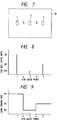
- the photographer's eye-gaze point is near the intermediate point a between the focus detection area 1 and the focus detection area 2 and as shown in Figure 8 of the accompanying drawings, the object distance DI in the area 1 and the object distance D2 in the area 2 differ greatly from each other, the selected focus detection area will change over from the area 1 to the area 2 or from the area 2 to the area 1 simply if the eye-gaze point slightly moves unconsciously to right and left near the point a (the gaze of human being moves involuntarily even if it is gazing at one point).
- the photo-taking lens is reciprocally driven between driven positions R1 and R2 as shown in Figure 9 of the accompanying drawings, and this results in the waste of electric power.
- the object luminance B1 in the area 11 and the object luminance B2 in the area 12 differ greatly from each other, the selected photometry area will change over from the area 11 to the area 12 or from the area 12 to the area 11 simply if the eye-gaze point slightly moves unconsciously to right and left near the point a.
- the exposure amount as the result of automatic exposure control may greatly vary to E1 and E2 as shown in Figure 12 of the accompanying drawings.
- the eye-gaze point is moved from the left end to the right end of the picture plane or conversely, the selected photometry area will change over when the eye-gaze passes the point a and the point b and therefore, in conformity therewith, the exposure amount controlled will vary suddenly.
- the brightness of photographed moving images varies unnaturally suddenlly.
- Figure 1 is a schematic view showing the internal structure of a camera provided with eye-gaze detecting means according to an embodiment of the present invention.
- Figure 2 is a graph showing the relation between the eye-gaze point by the camera of the Figure 1 embodiment and weighting coefficients.
- Figure 3 is a graph showing the relation between the eye-gaze point and the lens driven position.
- Figure 4 is a schematic view showing the internal structure of a camera provided with eye-gaze detecting means according to another embodiment of the present invention.
- Figure 5 is a graph showing the relation between the eye-gaze point by the camera of the Figure 4 embodiment and weighting coefficients.
- Figure 6 is a graph showing the relation between the eye-gaze point and the exposure amount.
- Figure 7 shows the positions of focus detection areas and two particular eye-gaze points in the photographing picture plane.
- Figure 8 is a graph showing the relation between the two particular eye-gaze points shown in Figure 7 and focus detection state information (object distance information).
- Figure 9 is a graph showing the relation between the two particular eye-gaze points shown in Figure 7 and the lens driven position.
- Figure 10 shows the positions of photometry areas and two particular eye-gaze points in the photographing picture plane.
- Figure 11 is a graph showing the relation between the two particular eye-gaze points shown in Figure 10 and object luminance information.
- Figure 12 is a graph showing the relation between the two particular eye-gaze points shown in Figure 10 and the exposure amount.
- Figure 13 is a conceptional diagram of still another embodiment of the present invention.
- Figure 14 is a block diagram of the Figure 13 embodiment.
- Figure 15 shows the divided patterns of the photometry areas and eye-gaze detection areas in the photographing picture plane of the Figure 13 embodiment.
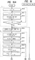
- Figure 16 is a flow chart showing the operation of a CPU in the Figure 13 embodiment.
- Figure 17 is a block diagram of yet still another embodiment of the present invention.
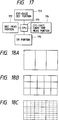
- Figures 18A to 18C show the divided patterns of focus detection areas (distance measuring areas and eye-gaze detection areas in the photographing picture plane of the Figure 17 embodiment.
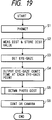
- Figure 19 is a flow chart showing the photographing operation of the Figure 17 embodiment.
- Figure 20 is a flow chart showing an example of the subroutine of Figure 19.
- Figure 21 is a flow chart showing another example of the subroutine of Figure 19.
- Figure 22 shows an example in which the divided patterns of the eye-gaze detection areas of Figure 15 have been changed.
- Figure 1 shows the internal structure of a camera according to an embodiment of the present invention. This camera effects automatic focus adjustment on the basis of the result of eye-gaze detection.
- the reference numeral 21 designates an eye-gaze detecting device for detecting the photographer's eye-gaze point in the photographing picture plane 10.
- the eye-gaze detecting device 21 is contained in a housing 22.
- the reference numeral 23 denotes a focus detecting apparatus for the camera.
- the focus detecting apparatus 23 is provided below the eye-gaze detecting device 21 and is contained in the housing 22.
- This focus detecting apparatus has contained therein a first calculating device (not shown) for calculating information values (information values relating to the object distances in a plurality of areas 1,-3 in the photographing picture plane 10) D1-D3 representative of the focus detection states of a photo-taking lens 24 corresponding to the plurality of focus detection areas 1-3 ( Figure 7) in the photographing picture plane 10.
- the reference numeral 25 designates a control device for controlling the amount of driving of the photo-taking lens 24 by a mean information value D calculated by itself.
- the control device 25 is connected to the focus detecting apparatus 23 and the eye-gaze detecting device 21.
- the mean information value D is calculated in the following manner by a second calculating device (not shown) contained in the control device 25.
- the reference numeral 26 denotes a motor for moving the photo-taking lens 24 in the direction of the optical axis thereof, and the reference numeral 27 designates a sub-mirror for directing a light beam transmitted through a half-mirror 28 to the focus detecting apparatus 23.
- the reference numeral 29 denotes a pentaprism, and the reference numeral 30 designates a finder screen.
- the eye-gaze point is at a point c indicated in the abscissa of Figure 2
- the weighting coefficients k1-k3 for this eye-gaze point c are determined in accordance with the coefficient characteristic lines of Figure 2, they are 0.65, 0.35 and 0, respectively, as indicated in the ordinate of Figure 2.
- the information values D1-D3 representative of the focus detection states in the focus detection areas 1-3 are values greatly differing from one another as shown in Figure 8, the mean information value D is as follows:
- the present embodiment has been shown with respect to a case where there are three focus detection areas 1-3, the present invention is not restricted thereto. There may be two focus detection areas, or four or more focus detection areas. Where there are four or more focus detection areas, the lens driving will be effected more smoothly.
- information values representative of the focus adjusted states of the photo-taking lens corresponding to the focus detection areas 1-n in the photographing picture plane are D1, D2, ⁇ , Dn
- the weighting coefficients of the focus detection areas 1-n are k1, k2, ⁇ , kn.
- the above-mentioned information values D1-D3 indicative of the focus detection states need not always correspond strictly to the object distances. Even information values (information from which can be known a rough standard of the amount of driving of the photo-taking lens necessary for focus adjustment and the direction of driving thereof) indicative of the amount and direction (front focus or rear focus) of defocus of the object image by the photo-taking lens can be applied to the present embodiment. In such case, if the detection of the information values and the calculation of the mean information value are repetitively effected while the photo-taking lens is driven, proper focus adjustment will be possible.
- the present invention is not restricted thereto, but design may be made such that automatic zooming is effected in the following manner on the basis of the mean information value D. That is, a motor for zooming is controlled so that the greater becomes the distance corresponding to the mean information value D, the more the photo-taking lens may be zoomed up and that the smaller becomes said distance, the more the photo-taking lens may be zoomed down, whereby the size of the object in the photographing picture plane can be made constant irrespective of the object distance.
- This camera effects automatic exposure control on the basis of the result of eye-gaze detection.
- FIG 4 is a schematic view showing the internal structure of the camera according to this embodiment.
- the reference numeral 31 designates an eye-gaze detecting device for detecting the photographer's eye-gaze point in the photographing picture plane 10.
- the eye-gaze detecting device 31 is contained in a housing 32.
- the reference numeral 33 denotes a photometry device for the camera.
- the photometry device 33 is provided above the eye-gaze detecting device 31 and is contained in the housing 32.
- This photometry device 33 has contained therein a first calculating device (not shown) for calculating information values B1-B3 representative of object luminances in a plurality of photometry areas 11-13 ( Figure 10) in the photographing picture plane 10.
- the reference numeral 34 designates a control device for controlling the shutter speed of a shutter 35 and the amount of aperture of a stop 36 on the basis of a mean information value B calculated by itself.
- the control device 34 is connected to the photometry device 33 and the eye-gaze detecting device 31.
- the mean information value B is calculated in the following manner by a second calculating device (not shown) contained in the control device 34.
- the reference numeral 37 denotes a mirror
- the reference numeral 38 designates a pentaprism
- the reference numeral 39 denotes a finder screen
- the reference numeral 40 designates a photo-taking lens.
- the eye-gaze point is at a point c indicated in the abscissa of Figure 5
- the weighting coefficients k11-k13 for this eye-gaze point c are determined in accordance with the coefficient characteristic lines of Figure 5, the are 0.65, 0.35 and 0, respectively, as shown in the ordinate of Figure 5.
- the mean information value B is as shown below.
- Figures 13 to 16 show a camera according to still another embodiment of the present invention. This camera effects automatic exposure on the basis of the result of eye-gaze detection.
- the epitome of the present invention will first be described with reference to Figure 13.
- the gaze position of the photographer's eye looking into the finder is detected time-serially.
- the amount of eye-gaze at each photometry area (zone) is measured.
- the object luminance in each zone is measured.
- weighting based on the amount of eye-gaze at each zone obtained at the step 132 is effected to the object luminance at each zone obtained at the step 133.
- a means exposure value is calculated on the basis of the result of said weighting.
- the exposure calculating device in this embodiment is comprised chiefly of a control unit (CPU) 141 for controlling the system of the camera, and the CPU 141 has connected thereto the outputs from a release button 142, an eye-gaze detecting device 143 and a divisional photometry device 144.
- the output of the CPU 141 is connected to an indicator 145 and an exposure control device 146.
- the eye-gaze detecting device 143 and the divisional photometry device 144 divide the interior of the finder into five zones 151-155, i.e., the central portion, the top left portion, the top right portion, the bottom left portion and the bottom right portion, during photographing and effect eye-gaze detection and photometry, respectively, at each of the zones 151-155.
- the release button 142 is provided on a camera body, not shown, and by the photographer depressing the release button 142, a signal for photographing direction or the like is output to the CPU 141.
- the eye-gaze detecting device 143 is a device for detecting in which of the zones 151-155 the photographer's eye-gaze in the finder is positioned.
- the eye-gaze detecting device 143 use can be made, for example, of a device which applies infrared illuminating light to the photographer's eye and detects the position of the eye-gaze by the reflected image from the cornea or the crystal lens (for example, the device disclosed in Japanese Laid-Open Patent Application No. 1-274736).
- the divisional photometry device 144 is a device for measuring the object luminance in the finder at each of the zones 151-155 shown in Figure 15, and it outputs the obtained luminance information to the CPU 141, which thus calculates the exposure value.
- the indicator 145 is a device for indicating the eye-gaze point position detected by the eye-gaze detecting device 143 and the exposure value calculated by the CPU 141.
- the exposure control device 146 is a device for controlling a shutter 147 and a stop 148 during photographing in conformity with the exposure value calculated by the CPU 141.
- n at #100 is a variable representative of the frequency of eye-gaze detection and is first set to 0.
- n+1 is substituted for n, and at #102, the first eye-gaze position detection is effected (this corresponds to the step 132 of Figure 13).
- the photographer's eye-gaze position is represented by X-Y coordinates having the center of the finder as the origin, and the coordinates data is defined as Dn(X, Y).
- the detection of the eye-gaze position is effected 500 times at intervals of 5 ms, and the routine of #102 - #103 is executed until n reaches 500 times as shown at #103.
- the routine of #102 - #103 is executed until n reaches 500 times as shown at #103.
- shift is made to #104.
- B(I) is a variable representative of the luminance of each of the zones 151-155
- I is a number indicative of the correspondence to the five zones
- 1-5 are allotted as I to the zones 151-155.
- the block II comprising #105 - #109 is a block for the eye-gaze detection after the aforedescribed 500 times of eye-gaze detection have been effected.
- the 501st eye-gaze position detection is effected and the coordinates data thereof is defined as D501(X, Y). Then at #106, the first coordinates data D1(X, Y) is erased, whereby the renewal of data is effected and stored in the CPU 141.
- #107 and #108 perform operations similar to the aforedescribed #100 and #101, and #109 shows that as described previously in connection with #106, the coordinates data D n+1 (X, Y) of the obtained eye-gaze position is replaced by coordinates data D n (X, Y).
- the coordinates data of the eye-gaze position are sequentially renewed to the newest data, and the number of the coordinates data are always kept at 500. Accordingly, even when much time is put in framing or the like, the coordinates data of the newest eye-gaze position is obtained.
- the eye-gaze frequency Q(I) for the five zones 151-155 is calculated from the obtained coordinates data of the eye-gaze position, and before that, at #110, Q(1) is set to the initial value 0.
- I is a number indicative of the correspondence to the five zones, and 1-5 are allotted as I to the zones 151-155.
- Shift is then made to a block III for calculating the eye-gaze frequency for each zone.
- the block III comprises #111 - #121, and is a block for discriminating which of the zones 151-155 the respective ones of the 500 coordinates data D n (X, Y) detected in the afore-described blocks I and II belong to.
- the routine of #111 - #121 is repeated until as shown at #121, the frequency of eye-gaze detection reaches 500 times, and the frequency discriminated for each zone becomes the frequency Q(I) corresponding to the final zones 151-155.
- weighting is effected to the exposure value B by the following equation (this corresponds to the steps 134 and 135 of Figure 13).
- each of Q(1) - Q(5) is divided by 500 to thereby find the proportion of eye-gaze times paid to the zones 151-155, and this proportion is multiplied by the object luminance B(I) for each zone measured at #104 to thereby find the arithmetical means, and weighting is effected to the exposure value B. Therefore, the exposure value B is determined by the photographer's eye-gaze times to the zones 151-155, and the photographer's intention is sufficiently reflected upon exposure control.
- the shapes of the divided zones for effecting photometry and the divided zones for eye-gaze detection are the same, whereas they need not always be the same, but for example, the divided zones for eye-gaze detection may be made narrower than the divided zones for photometry so as to be included in the divided zones for photometry. Also, the divided zones for photometry may be farther subdivided than in Figure 15.
- Figure 22 shows an example in which the eye-gaze detection areas are made narrower than the photometry areas.
- the eye-gaze detection areas comprise horizontally 12 divisions x vertically 8 divisions, totalling to 96 divisions. These eye-gaze detection areas, as indicated by thick lines in Figure 22, are approximated to the divided shapes of the photometry areas 151-155 of Figure 15 and are grouped for use for said weighting.
- the control as described in connection with Figures 5 and 6 will also become possible by using the result of the detection of the eye-gaze detection areas correspondingly to the focus detection areas differing in divided shape from the photometry areas 151-155, for example, the focus detection areas 1-3 of Figure 7. If this is done, automatic exposure control and automatic focus adjustment can be accomplished on the basis of the output of a single eye-gaze detecting device and therefore, construction will become simple.
- the weighting of the exposure value B may be calculated by the use of the following equation, instead of the aforementioned equation.
- weighting to each photometric output is effected by the moment of the square of the eye-gaze continuation time and therefore, as compared with the case of #22, more importance can be attached to the areas which are gazed at for a long time.
- eye-gaze detection is effected at predetermined time (5 milliseconds) intervals and therefore, the result is the eye-gaze continuation time for each area within a predetermined time before photographing.
- this can also be said to be a frequency indicative of how many times of the predetermined times (500 times) of eye-gaze detection each area has been gazed.
- the present invention is not restricted thereto, but also covers counting a simple eye-gaze frequency (number of times) which does not take the time element into account.
- FIG 17 shows a block diagram of a camera according to the present embodiment, which is comprised of a CPU 171, a distance measuring portion 172, an eye-gaze detecting portion 173, an eye-gaze continuation time measuring portion 174 and a driving portion 175.
- the CPU 171 is a control device for effecting the various controls of the camera.
- the distance measuring portion 172 measures the object distances in distance measuring areas obtained by dividing the photographing picture plane.
- the eye-gaze detecting portion 173 detects which portion of eye-gaze detection areas obtained by dividing the photographing picture plane the photographer is gazing at.
- the eye-gaze continuation time measuring portion 174 includes a counter and measures the eye-gaze continuation time for each eye-gaze detection area detected by the eye-gaze detecting portion 173.
- the counter counts the clock pulses generated by the CPU 171 while a certain eye-gaze detection area is gazed at, and the CPU 171 stores therein this count number for each eye-gaze detection area. By reading this stored count number, the eye-gaze continuation time for each area can be found.
- the driving portion 175 is a driving device for driving the lens on the basis of distance information.
- Figures 18A to 18C are illustrations showing the eye-gaze detection areas of the eye-gaze detecting portion 173 and the distance measuring areas of the distance measuring device for the photographing picture plane of the camera of the present embodiment.
- Figure 18A shows an example in which the photographing picture plane divided horizontally into three
- Figure 18B shows an example in which the photographing picture plane is divided vertically into three and divided horizontally into five, thus generally divided into fifteen.
- areas partitioned by solid lines indicate distance measuring areas
- areas partitioned by broken lines indicate eye-gaze detection areas.
- the distance measuring areas are provided by dividing the photographing picture plane both vertically and horizontally into three, thus into nine in total, and the eye-gaze detection areas indicate detection areas for the eye-gaze position provided by further dividing the distance measuring areas into nine, thus generally into eighty-one.
- the detection areas of the distance measuring device and the detection areas for the eye-gaze position are not limited to those described above.
- FIG 19 is a flow chart showing the photographing operation of the camera of the present embodiment. This photographing operation is started by depressing the shutter release button.
- a step S1 photometry is effected and the photometric value is memorized.
- the distance measurement of the individual distance measuring areas shown in Figure 18 is effected by the distance measuring portion 172 and each distance measurement value is memorized.
- the photographer's eye-gaze position is detected by the eye-gaze detecting portion 173. This detection is effected for a predetermined time (e.g. 1 second).
- the eye-gaze continuation time detected at the step S3 is output by the eye-gaze continuation time measuring portion 174.
- the photographing distance is determined with the eye-gaze continuation time at each eye-gaze detection area taken into account. This will be described later in greater detail.
- the photo-taking lens is driven so as to be focused to the photographing distance determined at the step S5, whereafter exposure is effected on the basis of the photometric value obtained at the step S1, and post-exposure processes such as film advance and shutter charge are carried out, thus terminating the photographing operation.
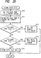
- Figure 20 is a flow chart of a subroutine showing the substance of the process of determining the photographing distance to which the photo-taking lens is focused at the step S5.
- the eye-gaze detection area P1 of the longest eye-gaze continuation time is selected from among the eye-gaze positions selected at the step S10.
- the distance measurement value of the distance measuring area corresponding to the eye-gaze detection area P1 and the distance measurement value or values corresponding to one or more other eye-gaze detection areas for which the difference in eye-gaze continuation time from the eye-gaze detection area P1 is within the predetermined value t1 are compared with one another, whereby the information of the closest object distance is selected as the photographing distance.
- weighting mean conforming to the eye-gaze continuation time for each area is effected to the distance measurement value of the distance measuring area corresponding to the eye-gazed detection area P1 and the distance measurement value or values corresponding to one or more other eye-gaze detection areas for which the difference in eye-gaze continuation time from the eye-gaze detection area P1 is within the predetermined value t2, and the result of it is adopted as the photographing distance.
- the distance measurement value corresponding to the eye-gaze detection area P1 is determined as the photographing distance. This is because the eye-gaze continuation time for the eye-gaze detection area P1 is longer beyond the predetermined value t2 than the eye-gaze continuation time for each of the other eye-gaze detection areas and therefore the eye-gaze detection area P1 can be regarded as the main object on which the photo-taking lens should be focused.
- Figure 21 is a flow chart of the subroutine showing another example of the process of the step S5 of the present embodiment.
- Steps S20 to S24 are the same as the steps S10 to S14 of Figure 20.
- the photographing distance is set so that the photo-taking lens may be focused without fail on an object which is at the distance measurement value corresponding to the eye-gaze detection area P1 and an object or objects corresponding to an object or objects which are at the distance measurement value or values of one or more other eye-gaze detection areas for which the difference in eye-gaze continuation time exceeds the predetermined value t1 and is within the predetermined value t2 may also be within the depth of field as far as possible.
- the depth of field is enlarged. This enlargement of the depth of field is accomplished by stopping down, but the amount of the stopping down is limited within a range in which under exposure and the hand vibration by a reduction is shutter speed do not occur.
- a step S26 and subsequent steps are the same as the step S16 and subsequent steps of Figure 20.
- the ratio between the horizontal dimension and vertical dimension of each eye-gaze detection area is smaller than the ratio between the horizontal dimension and vertical dimension of the photographing picture plane. This shows that the resolving power in the horizontal direction of eye-gaze detection is higher than the resolving power in the vertical direction. Since the eyes of human beings move more often in the horizontal direction than in the vertical direction, it is rational to make the resolving power in the horizontal direction of eye-gaze detection higher.
- eye-gaze has been used throughout the foregoing description, and is intended to refer simply to the camera user looking at the photographic picture plane in an ordinary way. No implication of a particularly fixed or intent look is intended by the use of this term.
Priority Applications (4)
| Application Number | Priority Date | Filing Date | Title |
|---|---|---|---|
| EP95109064A EP0680723A3 (de) | 1990-10-12 | 1991-10-14 | Kamera fähig zur Detektierung eines Anstauners. |
| EP95109068A EP0680724A3 (de) | 1990-10-12 | 1991-10-14 | Kamera fähig zur Detektierung eines Anstauners. |
| EP95109069A EP0680725A3 (de) | 1990-10-12 | 1991-10-14 | Kamera fähig zur Detektierung eines Anstauners. |
| EP95109070A EP0680726A3 (de) | 1990-10-12 | 1991-10-14 | Kamera fähig zur Detektierung eines Anstauners. |
Applications Claiming Priority (6)
| Application Number | Priority Date | Filing Date | Title |
|---|---|---|---|
| JP272174/90 | 1990-10-12 | ||
| JP2272174A JPH04149413A (ja) | 1990-10-12 | 1990-10-12 | 視線検出手段を備えたカメラ |
| JP287723/90 | 1990-10-25 | ||
| JP28772390 | 1990-10-25 | ||
| JP291434/90 | 1990-10-29 | ||
| JP2291434A JPH04163537A (ja) | 1990-10-29 | 1990-10-29 | 視線検知手段を有する多点測距装置 |
Related Child Applications (4)
| Application Number | Title | Priority Date | Filing Date |
|---|---|---|---|
| EP95109068.7 Division-Into | 1991-10-14 | ||
| EP95109069.5 Division-Into | 1991-10-14 | ||
| EP95109064.6 Division-Into | 1991-10-14 | ||
| EP95109070.3 Division-Into | 1991-10-14 |
Publications (2)
| Publication Number | Publication Date |
|---|---|
| EP0480774A1 true EP0480774A1 (de) | 1992-04-15 |
| EP0480774B1 EP0480774B1 (de) | 1997-04-16 |
Family
ID=27335978
Family Applications (5)
| Application Number | Title | Priority Date | Filing Date |
|---|---|---|---|
| EP95109064A Withdrawn EP0680723A3 (de) | 1990-10-12 | 1991-10-14 | Kamera fähig zur Detektierung eines Anstauners. |
| EP91309423A Expired - Lifetime EP0480774B1 (de) | 1990-10-12 | 1991-10-14 | Kamerasteuerung |
| EP95109070A Withdrawn EP0680726A3 (de) | 1990-10-12 | 1991-10-14 | Kamera fähig zur Detektierung eines Anstauners. |
| EP95109069A Withdrawn EP0680725A3 (de) | 1990-10-12 | 1991-10-14 | Kamera fähig zur Detektierung eines Anstauners. |
| EP95109068A Withdrawn EP0680724A3 (de) | 1990-10-12 | 1991-10-14 | Kamera fähig zur Detektierung eines Anstauners. |
Family Applications Before (1)
| Application Number | Title | Priority Date | Filing Date |
|---|---|---|---|
| EP95109064A Withdrawn EP0680723A3 (de) | 1990-10-12 | 1991-10-14 | Kamera fähig zur Detektierung eines Anstauners. |
Family Applications After (3)
| Application Number | Title | Priority Date | Filing Date |
|---|---|---|---|
| EP95109070A Withdrawn EP0680726A3 (de) | 1990-10-12 | 1991-10-14 | Kamera fähig zur Detektierung eines Anstauners. |
| EP95109069A Withdrawn EP0680725A3 (de) | 1990-10-12 | 1991-10-14 | Kamera fähig zur Detektierung eines Anstauners. |
| EP95109068A Withdrawn EP0680724A3 (de) | 1990-10-12 | 1991-10-14 | Kamera fähig zur Detektierung eines Anstauners. |
Country Status (3)
| Country | Link |
|---|---|
| US (4) | US5333029A (de) |
| EP (5) | EP0680723A3 (de) |
| DE (1) | DE69125682T2 (de) |
Cited By (5)
| Publication number | Priority date | Publication date | Assignee | Title |
|---|---|---|---|---|
| EP0572979A1 (de) * | 1992-06-02 | 1993-12-08 | Canon Kabushiki Kaisha | Optisches gerät mit Blickrichtungserfassung |
| EP0650292A1 (de) * | 1993-10-04 | 1995-04-26 | Canon Kabushiki Kaisha | Bildaufnahmegerät mit Erkennung der Sichtlinie des Bedieners |
| US6035054A (en) * | 1992-10-29 | 2000-03-07 | Canon Kabushiki Kaisha | Visual axis detection apparatus and optical apparatus provided therewith |
| WO2003016981A1 (de) * | 2001-07-06 | 2003-02-27 | Carl Zeiss | Kopfmontiertes optisches durchsichtssystem |
| CN104871525A (zh) * | 2012-12-26 | 2015-08-26 | 索尼公司 | 图像处理装置、以及图像处理方法及程序 |
Families Citing this family (75)
| Publication number | Priority date | Publication date | Assignee | Title |
|---|---|---|---|---|
| JPH03214133A (ja) * | 1990-01-18 | 1991-09-19 | Nikon Corp | 焦点検出装置 |
| US5515130A (en) * | 1990-12-10 | 1996-05-07 | Nikon Corporation | Camera control device |
| JP3210027B2 (ja) | 1991-04-05 | 2001-09-17 | キヤノン株式会社 | カメラ |
| DE4215523C2 (de) * | 1991-05-13 | 2002-12-05 | Canon Kk | Blickpunkterfassungseinrichtung für eine Kamera |
| US5758201A (en) * | 1991-06-28 | 1998-05-26 | Nikon Corporation | Camera having line of sight detecting device |
| US5614985A (en) * | 1992-10-28 | 1997-03-25 | Canon Kabushiki Kaisha | Camera with device for detecting line of sight |
| JPH06148505A (ja) * | 1992-10-30 | 1994-05-27 | Nikon Corp | 視線検知装置付きカメラ |
| JPH06313842A (ja) * | 1993-04-28 | 1994-11-08 | Canon Inc | 自動焦点カメラ |
| JPH06337343A (ja) * | 1993-05-31 | 1994-12-06 | Nikon Corp | 視線検知装置付きカメラ |
| JPH07128583A (ja) * | 1993-10-29 | 1995-05-19 | Canon Inc | ズーム機能付レンズシャッタカメラ |
| US5581323A (en) * | 1993-11-29 | 1996-12-03 | Canon Kabushiki Kaisha | Optical apparatus for controlling operations based on a user's visual axis |
| US6388707B1 (en) * | 1994-04-12 | 2002-05-14 | Canon Kabushiki Kaisha | Image pickup apparatus having means for appointing an arbitrary position on the display frame and performing a predetermined signal process thereon |
| JPH07311331A (ja) * | 1994-05-18 | 1995-11-28 | Nikon Corp | 視線検出装置を備えるカメラ |
| JPH08271784A (ja) * | 1995-03-30 | 1996-10-18 | Canon Inc | 視線検出機能付き光学機器 |
| US6538697B1 (en) * | 1995-04-26 | 2003-03-25 | Canon Kabushiki Kaisha | Man-machine interface apparatus and method |
| US5913079A (en) * | 1995-07-31 | 1999-06-15 | Canon Kabushiki Kaisha | Optical apparatus having a line of sight detection device |
| US6373961B1 (en) | 1996-03-26 | 2002-04-16 | Eye Control Technologies, Inc. | Eye controllable screen pointer |
| US7076118B1 (en) | 1997-12-05 | 2006-07-11 | Sharp Laboratories Of America, Inc. | Document classification system |
| US5839000A (en) * | 1997-11-10 | 1998-11-17 | Sharp Laboratories Of America, Inc. | Automatic zoom magnification control using detection of eyelid condition |
| US6220706B1 (en) | 2000-02-10 | 2001-04-24 | Carl Zeiss, Inc. | Method and apparatus for determining position of an eye |
| US6456788B1 (en) * | 2000-08-21 | 2002-09-24 | Canon Kabushiki Kaisha | Optical apparatus and camera provided with line-of-sight detecting device |
| US6965394B2 (en) * | 2001-03-30 | 2005-11-15 | Koninklijke Philips Electronics N.V. | Remote camera control device |
| US7561793B2 (en) * | 2002-11-12 | 2009-07-14 | Eastman Kodak Company | User interface for controlling cropping in electronic camera |
| US7006764B2 (en) * | 2002-11-12 | 2006-02-28 | Eastman Kodak Company | User interface for controlling cropping in electronic camera |
| US6907194B2 (en) | 2002-11-12 | 2005-06-14 | Eastman Kodak Company | Camera having continuously cropping viewfinder |
| US7206022B2 (en) | 2002-11-25 | 2007-04-17 | Eastman Kodak Company | Camera system with eye monitoring |
| US7046924B2 (en) | 2002-11-25 | 2006-05-16 | Eastman Kodak Company | Method and computer program product for determining an area of importance in an image using eye monitoring information |
| US7327890B2 (en) * | 2002-12-20 | 2008-02-05 | Eastman Kodak Company | Imaging method and system for determining an area of importance in an archival image |
| US7872635B2 (en) * | 2003-05-15 | 2011-01-18 | Optimetrics, Inc. | Foveated display eye-tracking system and method |
| US7705908B2 (en) * | 2003-12-16 | 2010-04-27 | Eastman Kodak Company | Imaging method and system for determining camera operating parameter |
| US20050134719A1 (en) * | 2003-12-23 | 2005-06-23 | Eastman Kodak Company | Display device with automatic area of importance display |
| US8659619B2 (en) | 2004-03-26 | 2014-02-25 | Intellectual Ventures Fund 83 Llc | Display device and method for determining an area of importance in an original image |
| US20060044399A1 (en) * | 2004-09-01 | 2006-03-02 | Eastman Kodak Company | Control system for an image capture device |
| JP4537192B2 (ja) * | 2004-12-21 | 2010-09-01 | キヤノン株式会社 | 眼科装置 |
| US7697827B2 (en) | 2005-10-17 | 2010-04-13 | Konicek Jeffrey C | User-friendlier interfaces for a camera |
| US8467672B2 (en) * | 2005-10-17 | 2013-06-18 | Jeffrey C. Konicek | Voice recognition and gaze-tracking for a camera |
| JP4961914B2 (ja) * | 2006-09-08 | 2012-06-27 | ソニー株式会社 | 撮像表示装置、撮像表示方法 |
| US7855743B2 (en) * | 2006-09-08 | 2010-12-21 | Sony Corporation | Image capturing and displaying apparatus and image capturing and displaying method |
| JP2008067219A (ja) | 2006-09-08 | 2008-03-21 | Sony Corp | 撮像装置、撮像方法 |
| US7860382B2 (en) * | 2006-10-02 | 2010-12-28 | Sony Ericsson Mobile Communications Ab | Selecting autofocus area in an image |
| US8808164B2 (en) * | 2008-03-28 | 2014-08-19 | Intuitive Surgical Operations, Inc. | Controlling a robotic surgical tool with a display monitor |
| US8155479B2 (en) | 2008-03-28 | 2012-04-10 | Intuitive Surgical Operations Inc. | Automated panning and digital zooming for robotic surgical systems |
| US8482626B2 (en) | 2009-04-07 | 2013-07-09 | Mediatek Inc. | Digital camera and image capturing method |
| US8482562B2 (en) | 2009-12-03 | 2013-07-09 | International Business Machines Corporation | Vision-based computer control |
| US8531394B2 (en) * | 2010-07-23 | 2013-09-10 | Gregory A. Maltz | Unitized, vision-controlled, wireless eyeglasses transceiver |
| US8531355B2 (en) | 2010-07-23 | 2013-09-10 | Gregory A. Maltz | Unitized, vision-controlled, wireless eyeglass transceiver |
| EP2774353A4 (de) * | 2011-11-03 | 2015-11-18 | Intel Corp | Auf augenverfolgung basierende bilderfassung |
| CN103246044B (zh) * | 2012-02-09 | 2017-03-22 | 联想(北京)有限公司 | 一种自动对焦方法、系统及具有该系统的照相机和摄像机 |
| US8988519B2 (en) * | 2012-03-20 | 2015-03-24 | Cisco Technology, Inc. | Automatic magnification of data on display screen based on eye characteristics of user |
| US9148537B1 (en) * | 2012-05-18 | 2015-09-29 | hopTo Inc. | Facial cues as commands |
| US9395826B1 (en) | 2012-05-25 | 2016-07-19 | hopTo Inc. | System for and method of translating motion-based user input between a client device and an application host computer |
| WO2014115387A1 (ja) * | 2013-01-28 | 2014-07-31 | ソニー株式会社 | 情報処理装置、情報処理方法およびプログラム |
| KR102013708B1 (ko) | 2013-03-29 | 2019-08-23 | 삼성전자주식회사 | 자동 초점 설정 방법 및 이를 위한 장치 |
| US20150003819A1 (en) * | 2013-06-28 | 2015-01-01 | Nathan Ackerman | Camera auto-focus based on eye gaze |
| WO2015066475A1 (en) | 2013-10-31 | 2015-05-07 | The University of North Carlina at Chapel Hill | Methods, systems, and computer readable media for leveraging user gaze in user monitoring subregion selection systems |
| KR102233728B1 (ko) * | 2013-10-31 | 2021-03-30 | 삼성전자주식회사 | 전자 장치의 제어 방법, 장치 및 컴퓨터 판독 가능한 기록 매체 |
| KR20170039282A (ko) | 2014-08-03 | 2017-04-10 | 포고텍, 인크. | 웨어러블 카메라 시스템 및 카메라 시스템 또는 다른 전자 디바이스를 웨어러블 물품에 부착하기 위한 장치 및 방법 |
| US9635222B2 (en) * | 2014-08-03 | 2017-04-25 | PogoTec, Inc. | Wearable camera systems and apparatus for aligning an eyewear camera |
| TW201724837A (zh) | 2014-12-23 | 2017-07-01 | 帕戈技術股份有限公司 | 穿戴式相機、用於提供無線電力之系統,用於以無線方式提供電力之方法及用於處理影像之方法 |
| US10567641B1 (en) | 2015-01-19 | 2020-02-18 | Devon Rueckner | Gaze-directed photography |
| GB201507210D0 (en) | 2015-04-28 | 2015-06-10 | Microsoft Technology Licensing Llc | Eye gaze correction |
| GB201507224D0 (en) | 2015-04-28 | 2015-06-10 | Microsoft Technology Licensing Llc | Eye gaze correction |
| US10481417B2 (en) | 2015-06-10 | 2019-11-19 | PogoTec, Inc. | Magnetic attachment mechanism for electronic wearable device |
| CN107924071A (zh) | 2015-06-10 | 2018-04-17 | 波戈技术有限公司 | 具有用于电子可佩戴装置的磁轨的眼镜 |
| JP6553418B2 (ja) * | 2015-06-12 | 2019-07-31 | パナソニック インテレクチュアル プロパティ コーポレーション オブ アメリカPanasonic Intellectual Property Corporation of America | 表示制御方法、表示制御装置及び制御プログラム |
| WO2017075405A1 (en) | 2015-10-29 | 2017-05-04 | PogoTec, Inc. | Hearing aid adapted for wireless power reception |
| US11558538B2 (en) | 2016-03-18 | 2023-01-17 | Opkix, Inc. | Portable camera system |
| EP3539285A4 (de) | 2016-11-08 | 2020-09-02 | Pogotec, Inc. | Intelligentes gehäuse für elektronische wearable-vorrichtung |
| WO2018118597A1 (en) * | 2016-12-23 | 2018-06-28 | Magic Leap, Inc. | Techniques for determining settings for a content capture device |
| JP7092108B2 (ja) * | 2017-02-27 | 2022-06-28 | ソニーグループ株式会社 | 情報処理装置、情報処理方法、及びプログラム |
| US9832372B1 (en) * | 2017-03-18 | 2017-11-28 | Jerry L. Conway, Sr. | Dynamic vediotelphony systems and methods of using the same |
| US11300857B2 (en) | 2018-11-13 | 2022-04-12 | Opkix, Inc. | Wearable mounts for portable camera |
| US11503204B2 (en) | 2019-12-19 | 2022-11-15 | Magic Leap, Inc. | Gradient-based exposure and gain control techniques |
| JP7467114B2 (ja) * | 2019-12-27 | 2024-04-15 | キヤノン株式会社 | 撮像装置およびその制御方法 |
| US20230379594A1 (en) * | 2022-05-20 | 2023-11-23 | Varjo Technologies Oy | Image blending |
Citations (5)
| Publication number | Priority date | Publication date | Assignee | Title |
|---|---|---|---|---|
| US4181408A (en) * | 1977-12-05 | 1980-01-01 | Senders John W | Vision compensation |
| US4607922A (en) * | 1984-04-09 | 1986-08-26 | Humphrey Instruments Incorporated | Method for aligning an eye examination instrument with the eye under examination |
| GB2196134A (en) * | 1986-09-30 | 1988-04-20 | Canon Kk | Auto-focus camera |
| DE3841575A1 (de) * | 1987-12-17 | 1989-07-13 | Asahi Optical Co Ltd | Einrichtung zur feststellung der blickrichtung des benutzers einer fotografischen kamera |
| US4974010A (en) * | 1989-06-09 | 1990-11-27 | Lc Technologies, Inc. | Focus control system |
Family Cites Families (15)
| Publication number | Priority date | Publication date | Assignee | Title |
|---|---|---|---|---|
| US4047187A (en) * | 1974-04-01 | 1977-09-06 | Canon Kabushiki Kaisha | System for exposure measurement and/or focus detection by means of image senser |
| US4574314A (en) * | 1982-05-28 | 1986-03-04 | Weinblatt Lee S | Camera autofocus technique |
| JPS59170822A (ja) * | 1983-03-17 | 1984-09-27 | Olympus Optical Co Ltd | 多点測光式カメラ |
| DE3473980D1 (en) * | 1984-02-17 | 1988-10-13 | Olympus Optical Co | Electronic photographing apparatus |
| ATE73311T1 (de) * | 1986-04-04 | 1992-03-15 | Applied Science Group Inc | Verfahren und geraet zur entwicklung der darstellung der sehzeitverteilung wenn leute fernsehwerbung beobachten. |
| JP2522260B2 (ja) * | 1986-10-08 | 1996-08-07 | キヤノン株式会社 | カメラ制御装置 |
| US4855780A (en) * | 1987-05-22 | 1989-08-08 | Canon Kabushiki Kaisha | Photometric device for pseudo format camera |
| JP2859270B2 (ja) * | 1987-06-11 | 1999-02-17 | 旭光学工業株式会社 | カメラの視線方向検出装置 |
| US4836670A (en) * | 1987-08-19 | 1989-06-06 | Center For Innovative Technology | Eye movement detector |
| JP2505854B2 (ja) * | 1988-03-23 | 1996-06-12 | キヤノン株式会社 | 視線検出手段を備えるカメラ |
| JP2763296B2 (ja) * | 1988-04-26 | 1998-06-11 | キヤノン株式会社 | 注視点方向検出装置を有する光学装置 |
| JP2950546B2 (ja) * | 1988-08-31 | 1999-09-20 | キヤノン株式会社 | 視線検出装置及び視線検出装置を有するカメラ |
| US4950069A (en) * | 1988-11-04 | 1990-08-21 | University Of Virginia | Eye movement detector with improved calibration and speed |
| US5253008A (en) * | 1989-09-22 | 1993-10-12 | Canon Kabushiki Kaisha | Camera |
| US5245381A (en) * | 1990-08-20 | 1993-09-14 | Nikon Corporation | Apparatus for ordering to phototake with eye-detection |
-
1991
- 1991-10-09 US US07/773,726 patent/US5333029A/en not_active Expired - Lifetime
- 1991-10-14 EP EP95109064A patent/EP0680723A3/de not_active Withdrawn
- 1991-10-14 DE DE69125682T patent/DE69125682T2/de not_active Expired - Fee Related
- 1991-10-14 EP EP91309423A patent/EP0480774B1/de not_active Expired - Lifetime
- 1991-10-14 EP EP95109070A patent/EP0680726A3/de not_active Withdrawn
- 1991-10-14 EP EP95109069A patent/EP0680725A3/de not_active Withdrawn
- 1991-10-14 EP EP95109068A patent/EP0680724A3/de not_active Withdrawn
-
1995
- 1995-06-07 US US08/477,590 patent/US5765045A/en not_active Expired - Lifetime
- 1995-06-07 US US08/477,591 patent/US5623703A/en not_active Expired - Lifetime
- 1995-06-07 US US08/472,726 patent/US5714988A/en not_active Expired - Lifetime
Patent Citations (5)
| Publication number | Priority date | Publication date | Assignee | Title |
|---|---|---|---|---|
| US4181408A (en) * | 1977-12-05 | 1980-01-01 | Senders John W | Vision compensation |
| US4607922A (en) * | 1984-04-09 | 1986-08-26 | Humphrey Instruments Incorporated | Method for aligning an eye examination instrument with the eye under examination |
| GB2196134A (en) * | 1986-09-30 | 1988-04-20 | Canon Kk | Auto-focus camera |
| DE3841575A1 (de) * | 1987-12-17 | 1989-07-13 | Asahi Optical Co Ltd | Einrichtung zur feststellung der blickrichtung des benutzers einer fotografischen kamera |
| US4974010A (en) * | 1989-06-09 | 1990-11-27 | Lc Technologies, Inc. | Focus control system |
Cited By (11)
| Publication number | Priority date | Publication date | Assignee | Title |
|---|---|---|---|---|
| EP0572979A1 (de) * | 1992-06-02 | 1993-12-08 | Canon Kabushiki Kaisha | Optisches gerät mit Blickrichtungserfassung |
| US5696998A (en) * | 1992-06-02 | 1997-12-09 | Canon Kabushiki Kaisha | Optical apparatus equipped with sight line detector |
| US5771402A (en) * | 1992-06-02 | 1998-06-23 | Canon Kabushiki Kaisha | Optical apparatus equipped with sight line detector |
| US5913080A (en) * | 1992-06-02 | 1999-06-15 | Canon Kabushiki Kaisha | Optical apparatus equipped with sight line detector |
| US5983029A (en) * | 1992-06-02 | 1999-11-09 | Canon Kabushiki Kaisha | Optical apparatus equipped with sight line detector |
| US6035054A (en) * | 1992-10-29 | 2000-03-07 | Canon Kabushiki Kaisha | Visual axis detection apparatus and optical apparatus provided therewith |
| EP0650292A1 (de) * | 1993-10-04 | 1995-04-26 | Canon Kabushiki Kaisha | Bildaufnahmegerät mit Erkennung der Sichtlinie des Bedieners |
| US6522360B1 (en) | 1993-10-04 | 2003-02-18 | Canon Kabushiki Kaisha | Image pickup apparatus performing autofocus processing and image enlargement in a common selected image plane region |
| WO2003016981A1 (de) * | 2001-07-06 | 2003-02-27 | Carl Zeiss | Kopfmontiertes optisches durchsichtssystem |
| CN104871525A (zh) * | 2012-12-26 | 2015-08-26 | 索尼公司 | 图像处理装置、以及图像处理方法及程序 |
| EP2940985A4 (de) * | 2012-12-26 | 2016-08-17 | Sony Corp | Bildverarbeitungsvorrichtung, bildverarbeitungsverfahren und programm dafür |
Also Published As
| Publication number | Publication date |
|---|---|
| US5765045A (en) | 1998-06-09 |
| EP0680725A2 (de) | 1995-11-08 |
| EP0680725A3 (de) | 1997-09-24 |
| US5333029A (en) | 1994-07-26 |
| US5623703A (en) | 1997-04-22 |
| EP0680724A2 (de) | 1995-11-08 |
| EP0480774B1 (de) | 1997-04-16 |
| DE69125682D1 (de) | 1997-05-22 |
| US5714988A (en) | 1998-02-03 |
| EP0680724A3 (de) | 1997-09-24 |
| EP0680726A2 (de) | 1995-11-08 |
| EP0680723A3 (de) | 1997-09-24 |
| EP0680726A3 (de) | 1997-09-24 |
| EP0680723A2 (de) | 1995-11-08 |
| DE69125682T2 (de) | 1997-10-23 |
Similar Documents
| Publication | Publication Date | Title |
|---|---|---|
| US5333029A (en) | Camera capable of detecting eye-gaze | |
| US5253008A (en) | Camera | |
| US5422700A (en) | Camera in which focus is detected to a plurality of viewfields within a observation block which is selected by visual axis detecting means | |
| US5515130A (en) | Camera control device | |
| US5091742A (en) | Camera having an auto focusing device | |
| US5255044A (en) | Automatic exposure control apparatus with improved exposure value calculation for photographing a moving object | |
| US5903788A (en) | Camera | |
| EP0438116B1 (de) | Einrichtung zur Fokussierungsdetektierung | |
| US4998126A (en) | Automatic focus adjustment camera | |
| US5515131A (en) | Optical apparatus having a function of inputting data of a visual axis | |
| US5041859A (en) | Automatic focusing detection device for cameras | |
| US5970258A (en) | Optical apparatus capable of performing a desired function by gazing | |
| EP0438140B1 (de) | Scharfeinstellungsgerät in einer Kamera | |
| US5216460A (en) | Automatic focusing camera | |
| JPH07181367A (ja) | マルチエリア焦点調節カメラ | |
| JP3352453B2 (ja) | カメラ | |
| JP3306666B2 (ja) | 自動焦点カメラ | |
| JP3471923B2 (ja) | カメラ | |
| JPH03107933A (ja) | 光学機器 | |
| JP3610218B2 (ja) | 自動焦点調節装置、撮像装置及び自動焦点調節方法 | |
| JP3416277B2 (ja) | 光学装置 | |
| JP3457973B2 (ja) | カメラの焦点検出装置 | |
| JPH07301846A (ja) | ファインダ内表示装置 | |
| JP3134440B2 (ja) | 視線検出装置付きカメラ | |
| JP3483366B2 (ja) | 視線検出手段を有するカメラ |
Legal Events
| Date | Code | Title | Description |
|---|---|---|---|
| PUAI | Public reference made under article 153(3) epc to a published international application that has entered the european phase |
Free format text: ORIGINAL CODE: 0009012 |
|
| AK | Designated contracting states |
Kind code of ref document: A1 Designated state(s): DE FR GB |
|
| 17P | Request for examination filed |
Effective date: 19921013 |
|
| 17Q | First examination report despatched |
Effective date: 19940803 |
|
| GRAG | Despatch of communication of intention to grant |
Free format text: ORIGINAL CODE: EPIDOS AGRA |
|
| GRAH | Despatch of communication of intention to grant a patent |
Free format text: ORIGINAL CODE: EPIDOS IGRA |
|
| GRAH | Despatch of communication of intention to grant a patent |
Free format text: ORIGINAL CODE: EPIDOS IGRA |
|
| GRAA | (expected) grant |
Free format text: ORIGINAL CODE: 0009210 |
|
| AK | Designated contracting states |
Kind code of ref document: B1 Designated state(s): DE FR GB |
|
| DX | Miscellaneous (deleted) | ||
| REF | Corresponds to: |
Ref document number: 69125682 Country of ref document: DE Date of ref document: 19970522 |
|
| ET | Fr: translation filed | ||
| PLBE | No opposition filed within time limit |
Free format text: ORIGINAL CODE: 0009261 |
|
| STAA | Information on the status of an ep patent application or granted ep patent |
Free format text: STATUS: NO OPPOSITION FILED WITHIN TIME LIMIT |
|
| 26N | No opposition filed | ||
| PGFP | Annual fee paid to national office [announced via postgrant information from national office to epo] |
Ref country code: FR Payment date: 19991011 Year of fee payment: 9 |
|
| PGFP | Annual fee paid to national office [announced via postgrant information from national office to epo] |
Ref country code: GB Payment date: 19991013 Year of fee payment: 9 |
|
| PG25 | Lapsed in a contracting state [announced via postgrant information from national office to epo] |
Ref country code: GB Free format text: LAPSE BECAUSE OF NON-PAYMENT OF DUE FEES Effective date: 20001014 |
|
| GBPC | Gb: european patent ceased through non-payment of renewal fee |
Effective date: 20001014 |
|
| PG25 | Lapsed in a contracting state [announced via postgrant information from national office to epo] |
Ref country code: FR Free format text: LAPSE BECAUSE OF NON-PAYMENT OF DUE FEES Effective date: 20010629 |
|
| REG | Reference to a national code |
Ref country code: FR Ref legal event code: ST |
|
| PGFP | Annual fee paid to national office [announced via postgrant information from national office to epo] |
Ref country code: DE Payment date: 20081014 Year of fee payment: 18 |
|
| PG25 | Lapsed in a contracting state [announced via postgrant information from national office to epo] |
Ref country code: DE Free format text: LAPSE BECAUSE OF NON-PAYMENT OF DUE FEES Effective date: 20100501 |