EP0480357A1 - Métier à filer à anneaux - Google Patents
Métier à filer à anneaux Download PDFInfo
- Publication number
- EP0480357A1 EP0480357A1 EP91117075A EP91117075A EP0480357A1 EP 0480357 A1 EP0480357 A1 EP 0480357A1 EP 91117075 A EP91117075 A EP 91117075A EP 91117075 A EP91117075 A EP 91117075A EP 0480357 A1 EP0480357 A1 EP 0480357A1
- Authority
- EP
- European Patent Office
- Prior art keywords
- drafting
- spinning machine
- motor
- inverter
- spindles
- Prior art date
- Legal status (The legal status is an assumption and is not a legal conclusion. Google has not performed a legal analysis and makes no representation as to the accuracy of the status listed.)
- Granted
Links
Images

Classifications
-
- D—TEXTILES; PAPER
- D01—NATURAL OR MAN-MADE THREADS OR FIBRES; SPINNING
- D01H—SPINNING OR TWISTING
- D01H1/00—Spinning or twisting machines in which the product is wound-up continuously
- D01H1/14—Details
- D01H1/20—Driving or stopping arrangements
- D01H1/32—Driving or stopping arrangements for complete machines
Definitions
- the invention relates to an operating method for a ring spinning machine with a drive device for the spindles and a further drive device for the drafting system.
- the spindles can be made a few turns after the spinning machine has been switched off in order to reduce the excess length of the yarn, as a result of which the claws should be pulled out.
- the associated slight increase in the number of twists in the yarn between the drafting system and the spindle can increase the tendency to form a crimp, especially in the case of twisted yarns, by means of a twist coefficient of the value 100.
- single motors are provided as drive devices for the spindles of the drafting system, it is advisable to provide at least one frequency converter consisting of a rectifier and an inverter, with the speed of the speed at a random point in time before switching off the spinning machine or for shutting down before switching off Drive motor for the drafting system is reduced, and the spindle shaft speed of the spindle motor is deflected only after a time interval.
- at least one frequency converter consisting of a rectifier and an inverter
- the twist of the yarn is reduced, which also lowers the tendency to jiggle.
- the same effects can be achieved in that the speed reduction in the drafting system or in the drive device for the spindles is not initiated at specific points in time pushed against one another, but rather that the speeds increase or decrease during the lowering of the speeds in the drafting device or in the drive device for the spindles be lowered less. By avoiding the formation of claws, the likelihood that yarn breaks will occur during the restart of the spinning machine is reduced.
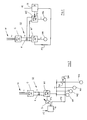
- spindles S1 are driven by a drive device M1 via a gear GE1.
- the drive device M1 can be a speed-controlled, electrical spindle motor.
- a shaft WE can lead to a transmission GE2 and this to a countershaft transmission V, which is connected to a transmission GE for the drafting device S4.
- a countershaft transmission V different output speeds can be selected for the GE transmission.
- a M4 drafting system motor e.g. a synchronous motor.
- the spindle motor M1 and the drafting gear motor M4 or the countershaft transmission V are connected to a controller R, which specifies the target frequencies FS for the spindle motor M1 and the target frequency FS 'for the drafting gear motor M4 via connecting lines between controller and spindle motor M1 or drafting gear motor M4.
- a connecting line between the controller R and the countershaft transmission V may transmit the specified switching function FS "for the countershaft transmission.
- the controller receives the specified programs for lowering the speed of the spindle motor M1, the drafting gear motor M4 or for the switching function FS" of the countershaft transmission V von a program memory P. Depending on the yarn to be produced in the spinning machine, various programs can be called up.
- a controller R controls, via a setpoint generator S, to which it transmits the setpoint frequency FS, an inverter W1, which supplies alternating current to motors M1 ... M4.
- the inverter W1 is about a rectifier G and a DC voltage intermediate circuit GZ with direct current.
- a capacitor K can be arranged in the DC voltage intermediate circuit GZ and can absorb electrical energy fed back via the inverter W1 when the spinning machine is shut down.
- the rectifier G is usually supplied by an AC voltage source W with 3-phase AC.
- a switch SA is located between the inverter W1 and the drafting motor M4 and the drafting motor M4 can be switched on.
- a servomotor SM is provided for the changeover, the switching function FS "being transmitted by the controller R.
- the motors M1 to M4 are preferably designed as synchronous motors.
- a rectifier G is connected to an AC voltage source W.
- a second inverter W2 for the drafting motor M4 is connected in the DC intermediate circuit GZ.
- the controller R in which the program memory P is shown as a component, controls both inverters W1 and W2 by transmitting the set frequencies FS or FS 'via connecting lines.
- the controller R receives a shutdown pulse AI, the target frequency FS 'in the inverter W2 is first lowered, while the target frequency FS of the inverter W1 is only reduced at a later point in time. This operating mode is preferable for weakly twisted yarn as described in the introduction.
- the program memory P must be designed in such a way that program changes can be carried out in a simple manner on the spinning machine if this is necessary when changing over to another yarn to be produced.
- the various options for carrying out the operating method are explained below using FIG. 4.
- the ordinate in the diagram shows speed N, time T runs in the direction of the abscissa.
- the spindle speed is designated NSA or NSB
- the drafting device speed is designated NW1, NW2, NW3 depending on the program.
- the spindle shaft speed NSB is continuously reduced from point C to point D to point E, to a standstill, due to a shutdown pulse AI.
- the drafting unit shaft speed NW3 drops from point H via point O in proportion to the spindle shaft speed NSA.
- TG indicates a point in time from which the speed is reduced more than before.
- the drafting shaft speed NW2 can already be reduced from the point H ", while the spindle shaft speed NSB initially remains constant until the time TA3 and is only then reduced.
- the time difference value DW1 is the time difference value DW1.
- the shutdown pulse AI is received in controller R at time TA2.
- the drafting system shaft speed NW2 is then abruptly reduced from point H 'to the value at point L in accordance with FIG. 4 and then continuously reduced further, while the spindle shaft speed NSA is still kept at the original level up to point C and only then drops.
- the speeds of the spindle motor M1 and the drafting motor M4 are simultaneously reduced when receiving a shutdown pulse AI at the time TA3, the spindle shaft speed NSB running over time from point C to point D and the drafting shaft speed NW3 from point H to point H
- the drafting system motor M4 is then braked more strongly up to the point L 'because its target frequency FS' is reduced more, as a result of which the drafting device shaft speed NW3 drops to a lower level NW2 at point L '.
- the drafting device shaft speed NW2 then becomes constant reduced to zero to point O and then further to point E. While all of the speed curves shown in FIG. 4 can be run with the circuit according to FIG.
- the drafting device speed NW2 can only be changed by leaps and bounds using the principle described in FIG Line train H "-H'-L.
- the switch SA according to FIG. 2 is actuated into the interruption position, the drafting system according to line NW3 runs out earlier than the spindles via the points H-O'-E '.
- the spindle shaft speed NSA before the drafting system shaft speed.
- the shutdown pulse AI is received in controller R at time TA4.
- the spindle shaft speed NSA is then lowered from point C 'to points D and E.
- NW3 the drafting system shaft speed
- the spinning yarn between drafting device S4 and spindle S1 is rotated less until the spinning machine comes to a standstill, thereby preventing the formation of claws when the yarn is turned higher.
Applications Claiming Priority (2)
| Application Number | Priority Date | Filing Date | Title |
|---|---|---|---|
| CH324590 | 1990-10-09 | ||
| CH3245/90 | 1990-10-09 |
Publications (2)
| Publication Number | Publication Date |
|---|---|
| EP0480357A1 true EP0480357A1 (fr) | 1992-04-15 |
| EP0480357B1 EP0480357B1 (fr) | 1995-04-19 |
Family
ID=4251795
Family Applications (1)
| Application Number | Title | Priority Date | Filing Date |
|---|---|---|---|
| EP19910117075 Expired - Lifetime EP0480357B1 (fr) | 1990-10-09 | 1991-10-08 | Métier à filer à anneaux |
Country Status (2)
| Country | Link |
|---|---|
| EP (1) | EP0480357B1 (fr) |
| DE (1) | DE59105248D1 (fr) |
Cited By (1)
| Publication number | Priority date | Publication date | Assignee | Title |
|---|---|---|---|---|
| JP2001115343A (ja) * | 1999-09-20 | 2001-04-24 | Mas Fab Rieter Ag | スピンドルに締め付け装置を有するリング精紡機 |
Citations (4)
| Publication number | Priority date | Publication date | Assignee | Title |
|---|---|---|---|---|
| DE2753924A1 (de) * | 1977-12-03 | 1979-06-07 | Zinser Textilmaschinen Gmbh | Antriebseinrichtung fuer arbeitsorgane einer textilmaschine |
| US4518899A (en) * | 1983-03-16 | 1985-05-21 | Zinser Textilmaschinen Gmbh | Process and apparatus for correlating startup and cutoff periods of different induction motors with one another |
| DE3822420A1 (de) * | 1988-07-02 | 1990-01-04 | Skf Textilmasch Komponenten | Ringspinn-/oder ringzwirnmaschine |
| EP0389118A2 (fr) * | 1989-03-23 | 1990-09-26 | Hollingsworth (U.K.) Limited | Métiers à filer à anneaux, doubleuses à anneaux et métiers à retordre à anneaux avec moteur à reluctance pour entraîner la broche |
-
1991
- 1991-10-08 DE DE59105248T patent/DE59105248D1/de not_active Expired - Lifetime
- 1991-10-08 EP EP19910117075 patent/EP0480357B1/fr not_active Expired - Lifetime
Patent Citations (4)
| Publication number | Priority date | Publication date | Assignee | Title |
|---|---|---|---|---|
| DE2753924A1 (de) * | 1977-12-03 | 1979-06-07 | Zinser Textilmaschinen Gmbh | Antriebseinrichtung fuer arbeitsorgane einer textilmaschine |
| US4518899A (en) * | 1983-03-16 | 1985-05-21 | Zinser Textilmaschinen Gmbh | Process and apparatus for correlating startup and cutoff periods of different induction motors with one another |
| DE3822420A1 (de) * | 1988-07-02 | 1990-01-04 | Skf Textilmasch Komponenten | Ringspinn-/oder ringzwirnmaschine |
| EP0389118A2 (fr) * | 1989-03-23 | 1990-09-26 | Hollingsworth (U.K.) Limited | Métiers à filer à anneaux, doubleuses à anneaux et métiers à retordre à anneaux avec moteur à reluctance pour entraîner la broche |
Cited By (4)
| Publication number | Priority date | Publication date | Assignee | Title |
|---|---|---|---|---|
| JP2001115343A (ja) * | 1999-09-20 | 2001-04-24 | Mas Fab Rieter Ag | スピンドルに締め付け装置を有するリング精紡機 |
| US6487841B1 (en) | 1999-09-20 | 2002-12-03 | Maschinenfabrik Rieter Ag | Ring spinning frame with clamping device at the spindle |
| DE10037513B4 (de) * | 1999-09-20 | 2010-09-30 | Maschinenfabrik Rieter Ag | Verfahren zum Steuern einer Ringspinnmaschine und Spinnmaschine |
| JP4638584B2 (ja) * | 1999-09-20 | 2011-02-23 | マシーネンファブリク リーター アクチェンゲゼルシャフト | スピンドルに締め付け装置を有するリング精紡機 |
Also Published As
| Publication number | Publication date |
|---|---|
| DE59105248D1 (de) | 1995-05-24 |
| EP0480357B1 (fr) | 1995-04-19 |
Similar Documents
| Publication | Publication Date | Title |
|---|---|---|
| DE2911378C2 (fr) | ||
| DE3347113C2 (de) | Spinn- oder Zwirnmaschine mit Einzelantrieb | |
| EP0451534B1 (fr) | Machine textile, en particulier métier à filer à anneaux | |
| EP0094483B1 (fr) | Commande de broche de bobinage | |
| CH667884A5 (de) | Einrichtung zum betreiben einer spinnerei- oder zwirnereimaschine. | |
| EP0355557A1 (fr) | Machine textile avec un dispositif d'étirage | |
| DE69932961T2 (de) | Textilmaschine mit Einzelspindelantrieb wobei die Spindelantriebe in modularen Einheiten aufgeteilt sind. | |
| EP0349831B1 (fr) | Système d'entraînement synchronisable | |
| EP1048769B1 (fr) | Procédé de mise en marche d'un métier à tisser pourvu d'un entraínement principal à électro-moteur | |
| EP1078116B2 (fr) | Machine traitant une matiere textile et dotee d'un bac d'etirage | |
| EP0440025B1 (fr) | Dispositif d'entraînement d'une machine à filer à bout libre | |
| DE1685915B2 (fr) | ||
| EP0480357B1 (fr) | Métier à filer à anneaux | |
| DE19821251A1 (de) | Verfahren zum Betrieb einer Spinnmaschine | |
| DE4404503A1 (de) | Rotorspinnmaschine | |
| DE3741430C2 (fr) | ||
| EP0155472B1 (fr) | Procédé de commande d'entraînement de machines électriques | |
| DE3324243A1 (de) | Falschzwirnkraeuselmaschine und verfahren zur ueberbrueckung kurzzeitiger spannun gsausfaelle an textilmaschinen | |
| DE4039086A1 (de) | Spulenwickelvorrichtung und verfahren zu ihrem betrieb | |
| DE3822358A1 (de) | Antriebsverfahren fuer walzen eines spulautomaten | |
| EP0671355B1 (fr) | Stockage de ruban de fibres | |
| DE2228202A1 (de) | Einzelmotorantrieb einer drehbaren Spannhülse fur Spulgerate | |
| DE1959014A1 (de) | Textilmaschine mit Einrichtung zum gleichmaessigen Auslauf der Antriebsmotoren | |
| EP1442167A1 (fr) | Dispositif et procede d'alimentation en fil | |
| DE4205215A1 (de) | Verfahren und vorrichtung zur wechselweisen speisung des doffermotors einer ringspinnmaschine |
Legal Events
| Date | Code | Title | Description |
|---|---|---|---|
| PUAI | Public reference made under article 153(3) epc to a published international application that has entered the european phase |
Free format text: ORIGINAL CODE: 0009012 |
|
| 17P | Request for examination filed |
Effective date: 19920128 |
|
| AK | Designated contracting states |
Kind code of ref document: A1 Designated state(s): CH DE FR GB IT LI |
|
| 17Q | First examination report despatched |
Effective date: 19940202 |
|
| GRAA | (expected) grant |
Free format text: ORIGINAL CODE: 0009210 |
|
| AK | Designated contracting states |
Kind code of ref document: B1 Designated state(s): CH DE FR GB IT LI |
|
| PG25 | Lapsed in a contracting state [announced via postgrant information from national office to epo] |
Ref country code: FR Effective date: 19950419 Ref country code: GB Effective date: 19950419 |
|
| REF | Corresponds to: |
Ref document number: 59105248 Country of ref document: DE Date of ref document: 19950524 |
|
| ITF | It: translation for a ep patent filed |
Owner name: GUZZI E RAVIZZA S.R.L. |
|
| EN | Fr: translation not filed | ||
| GBV | Gb: ep patent (uk) treated as always having been void in accordance with gb section 77(7)/1977 [no translation filed] |
Effective date: 19950419 |
|
| PLBE | No opposition filed within time limit |
Free format text: ORIGINAL CODE: 0009261 |
|
| STAA | Information on the status of an ep patent application or granted ep patent |
Free format text: STATUS: NO OPPOSITION FILED WITHIN TIME LIMIT |
|
| 26N | No opposition filed | ||
| PGFP | Annual fee paid to national office [announced via postgrant information from national office to epo] |
Ref country code: CH Payment date: 19960920 Year of fee payment: 6 |
|
| PG25 | Lapsed in a contracting state [announced via postgrant information from national office to epo] |
Ref country code: CH Free format text: LAPSE BECAUSE OF NON-PAYMENT OF DUE FEES Effective date: 19971031 Ref country code: LI Free format text: LAPSE BECAUSE OF NON-PAYMENT OF DUE FEES Effective date: 19971031 |
|
| REG | Reference to a national code |
Ref country code: CH Ref legal event code: PL |
|
| PGFP | Annual fee paid to national office [announced via postgrant information from national office to epo] |
Ref country code: DE Payment date: 20101022 Year of fee payment: 20 |
|
| PGFP | Annual fee paid to national office [announced via postgrant information from national office to epo] |
Ref country code: IT Payment date: 20101026 Year of fee payment: 20 |
|
| REG | Reference to a national code |
Ref country code: DE Ref legal event code: R071 Ref document number: 59105248 Country of ref document: DE |
|
| REG | Reference to a national code |
Ref country code: DE Ref legal event code: R071 Ref document number: 59105248 Country of ref document: DE |
|
| PG25 | Lapsed in a contracting state [announced via postgrant information from national office to epo] |
Ref country code: DE Free format text: LAPSE BECAUSE OF EXPIRATION OF PROTECTION Effective date: 20111009 |