EP0480357A1 - Ring spinning machine - Google Patents
Ring spinning machine Download PDFInfo
- Publication number
- EP0480357A1 EP0480357A1 EP91117075A EP91117075A EP0480357A1 EP 0480357 A1 EP0480357 A1 EP 0480357A1 EP 91117075 A EP91117075 A EP 91117075A EP 91117075 A EP91117075 A EP 91117075A EP 0480357 A1 EP0480357 A1 EP 0480357A1
- Authority
- EP
- European Patent Office
- Prior art keywords
- drafting
- spinning machine
- motor
- inverter
- spindles
- Prior art date
- Legal status (The legal status is an assumption and is not a legal conclusion. Google has not performed a legal analysis and makes no representation as to the accuracy of the status listed.)
- Granted
Links
Images

Classifications
-
- D—TEXTILES; PAPER
- D01—NATURAL OR MAN-MADE THREADS OR FIBRES; SPINNING
- D01H—SPINNING OR TWISTING
- D01H1/00—Spinning or twisting machines in which the product is wound-up continuously
- D01H1/14—Details
- D01H1/20—Driving or stopping arrangements
- D01H1/32—Driving or stopping arrangements for complete machines
Definitions
- the invention relates to an operating method for a ring spinning machine with a drive device for the spindles and a further drive device for the drafting system.
- the spindles can be made a few turns after the spinning machine has been switched off in order to reduce the excess length of the yarn, as a result of which the claws should be pulled out.
- the associated slight increase in the number of twists in the yarn between the drafting system and the spindle can increase the tendency to form a crimp, especially in the case of twisted yarns, by means of a twist coefficient of the value 100.
- single motors are provided as drive devices for the spindles of the drafting system, it is advisable to provide at least one frequency converter consisting of a rectifier and an inverter, with the speed of the speed at a random point in time before switching off the spinning machine or for shutting down before switching off Drive motor for the drafting system is reduced, and the spindle shaft speed of the spindle motor is deflected only after a time interval.
- at least one frequency converter consisting of a rectifier and an inverter
- the twist of the yarn is reduced, which also lowers the tendency to jiggle.
- the same effects can be achieved in that the speed reduction in the drafting system or in the drive device for the spindles is not initiated at specific points in time pushed against one another, but rather that the speeds increase or decrease during the lowering of the speeds in the drafting device or in the drive device for the spindles be lowered less. By avoiding the formation of claws, the likelihood that yarn breaks will occur during the restart of the spinning machine is reduced.
- spindles S1 are driven by a drive device M1 via a gear GE1.
- the drive device M1 can be a speed-controlled, electrical spindle motor.
- a shaft WE can lead to a transmission GE2 and this to a countershaft transmission V, which is connected to a transmission GE for the drafting device S4.
- a countershaft transmission V different output speeds can be selected for the GE transmission.
- a M4 drafting system motor e.g. a synchronous motor.
- the spindle motor M1 and the drafting gear motor M4 or the countershaft transmission V are connected to a controller R, which specifies the target frequencies FS for the spindle motor M1 and the target frequency FS 'for the drafting gear motor M4 via connecting lines between controller and spindle motor M1 or drafting gear motor M4.
- a connecting line between the controller R and the countershaft transmission V may transmit the specified switching function FS "for the countershaft transmission.
- the controller receives the specified programs for lowering the speed of the spindle motor M1, the drafting gear motor M4 or for the switching function FS" of the countershaft transmission V von a program memory P. Depending on the yarn to be produced in the spinning machine, various programs can be called up.
- a controller R controls, via a setpoint generator S, to which it transmits the setpoint frequency FS, an inverter W1, which supplies alternating current to motors M1 ... M4.
- the inverter W1 is about a rectifier G and a DC voltage intermediate circuit GZ with direct current.
- a capacitor K can be arranged in the DC voltage intermediate circuit GZ and can absorb electrical energy fed back via the inverter W1 when the spinning machine is shut down.
- the rectifier G is usually supplied by an AC voltage source W with 3-phase AC.
- a switch SA is located between the inverter W1 and the drafting motor M4 and the drafting motor M4 can be switched on.
- a servomotor SM is provided for the changeover, the switching function FS "being transmitted by the controller R.
- the motors M1 to M4 are preferably designed as synchronous motors.
- a rectifier G is connected to an AC voltage source W.
- a second inverter W2 for the drafting motor M4 is connected in the DC intermediate circuit GZ.
- the controller R in which the program memory P is shown as a component, controls both inverters W1 and W2 by transmitting the set frequencies FS or FS 'via connecting lines.
- the controller R receives a shutdown pulse AI, the target frequency FS 'in the inverter W2 is first lowered, while the target frequency FS of the inverter W1 is only reduced at a later point in time. This operating mode is preferable for weakly twisted yarn as described in the introduction.
- the program memory P must be designed in such a way that program changes can be carried out in a simple manner on the spinning machine if this is necessary when changing over to another yarn to be produced.
- the various options for carrying out the operating method are explained below using FIG. 4.
- the ordinate in the diagram shows speed N, time T runs in the direction of the abscissa.
- the spindle speed is designated NSA or NSB
- the drafting device speed is designated NW1, NW2, NW3 depending on the program.
- the spindle shaft speed NSB is continuously reduced from point C to point D to point E, to a standstill, due to a shutdown pulse AI.
- the drafting unit shaft speed NW3 drops from point H via point O in proportion to the spindle shaft speed NSA.
- TG indicates a point in time from which the speed is reduced more than before.
- the drafting shaft speed NW2 can already be reduced from the point H ", while the spindle shaft speed NSB initially remains constant until the time TA3 and is only then reduced.
- the time difference value DW1 is the time difference value DW1.
- the shutdown pulse AI is received in controller R at time TA2.
- the drafting system shaft speed NW2 is then abruptly reduced from point H 'to the value at point L in accordance with FIG. 4 and then continuously reduced further, while the spindle shaft speed NSA is still kept at the original level up to point C and only then drops.
- the speeds of the spindle motor M1 and the drafting motor M4 are simultaneously reduced when receiving a shutdown pulse AI at the time TA3, the spindle shaft speed NSB running over time from point C to point D and the drafting shaft speed NW3 from point H to point H
- the drafting system motor M4 is then braked more strongly up to the point L 'because its target frequency FS' is reduced more, as a result of which the drafting device shaft speed NW3 drops to a lower level NW2 at point L '.
- the drafting device shaft speed NW2 then becomes constant reduced to zero to point O and then further to point E. While all of the speed curves shown in FIG. 4 can be run with the circuit according to FIG.
- the drafting device speed NW2 can only be changed by leaps and bounds using the principle described in FIG Line train H "-H'-L.
- the switch SA according to FIG. 2 is actuated into the interruption position, the drafting system according to line NW3 runs out earlier than the spindles via the points H-O'-E '.
- the spindle shaft speed NSA before the drafting system shaft speed.
- the shutdown pulse AI is received in controller R at time TA4.
- the spindle shaft speed NSA is then lowered from point C 'to points D and E.
- NW3 the drafting system shaft speed
- the spinning yarn between drafting device S4 and spindle S1 is rotated less until the spinning machine comes to a standstill, thereby preventing the formation of claws when the yarn is turned higher.
Abstract
Description
Die Erfindung betrifft ein Betriebsverfahren für eine Ringspinnmaschine mit einer Antriebseinrichtung für die Spindeln und einer weiteren Antriebseinrichtung für das Streckwerk.The invention relates to an operating method for a ring spinning machine with a drive device for the spindles and a further drive device for the drafting system.
In der Praxis beobachtet man nach dem Abstellen einer Ringspinnmaschine mehr oder weniger starke Krangelbildung am Garn zwischen Streckwerk und Spindeln. Diese Krangelbildung kann sich dann einstellen, wenn bei einer gewissen Verdrehung des Garnes die Spannung im Garn zu gering ist. Die Abnahme der Spannung rührt daher, dass nach dem Abstellen einer Ringspinnmaschine der Fadenballon an der Spinnstelle verschwindet, wodurch eine Ueberlänge an Garn zwischen Streckwerk und Spindel entsteht. Hochgedrehte Garne neigen mehr zur Krangelbildung als niedrig gedrehte Garne. Um die Krangelbildung zu vermeiden, kann man nach Abstellen der Spinnmaschine die Spindeln noch einige Umdrehungen machen lassen, um die Ueberlänge des Garnes abzubauen, wodurch die Krangel ausgezogen werden sollen. Durch die damit verbundene geringe Erhöhung der Drehungszahl im Garn zwischen Streckwerk und Spindel kann aber besonders bei höher gedrehten Garnen über einen Drehungskoeffizienten des Wertes 100 die Neigung zur Krangelbildung noch zunehmen.In practice, after a ring spinning machine has been switched off, more or less strong jigging on the yarn between the drafting system and the spindles is observed. This formation of a curl can occur if the tension in the yarn is too low with a certain twisting of the yarn. The decrease in tension is due to the fact that after a ring spinning machine has been switched off, the thread balloon at the spinning position disappears, as a result of which there is an excessive length of yarn between the drafting system and the spindle. Twisted yarns are more prone to swaying than twisted yarns. In order to avoid the formation of claws, the spindles can be made a few turns after the spinning machine has been switched off in order to reduce the excess length of the yarn, as a result of which the claws should be pulled out. The associated slight increase in the number of twists in the yarn between the drafting system and the spindle, however, can increase the tendency to form a crimp, especially in the case of twisted yarns, by means of a twist coefficient of the value 100.
Es ist Aufgabe der Erfindung, ein Betriebsverfahren für eine Ringspinnmaschine zu schaffen, welche für unterschiedliche Garnqualitäten die Bildung von Krangeln beim Abstellen der Spinnmaschine vermeidet.It is an object of the invention to provide an operating method for a ring spinning machine which avoids the formation of cranks when the spinning machine is switched off for different yarn qualities.
Diese Aufgabe wird dadurch gelöst, dass die Drehzahlen für das Streckwerk und die Drehzahlen der Spindeln beim Herunterfahren oder Hochfahren der Spinnmaschine nicht proportional zueinander, sondern unabhängig je nach einem vorgegebenen Programm reduziert bzw. gesteigert werden, so dass das Garn zwischen Streckwerk und Spinnkops nach dem Ausschalten der Spinnmaschine mehr oder weniger Drehungen als während des kontinuierlichen Spinnens aufweist. Vorteilhafte Weiterbildungen der Erfindung sind in den Unteransprüchen beschrieben. Wenn als Antriebseinrichtungen für die Spindeln des Streckwerks Einzelmotoren vorgesehen sind, ist es zweckmässig, mindestens einen Frequenzumrichter bestehend aus einem Gleichrichter und einem Wechselrichter Motoren vorzusehen, wobei vor dem Ausschalten der Spinnmaschine bzw. zum Herunterfahren vor dem Ausschalten zunächst zu einem willkürlichen Zeitpunkt die Drehzahl des Antriebsmotors für das Streckwerk reduziert wird, und erst nach einem Zeitintervall die Spindelwellendrehzahl des Spindelmotors abgelenkt wird. Bei höher gedrehten Garnen kann aber die Krangelbildung dadurch besser vermieden werden, dass zunächst die Drehzahl des Spindelmotors und dann erst die Drehzahl des Streckwerks reduziert wird. Im ersten Fall wird der Krangelbildung dadurch begegnet, dass weniger Garn geliefert wird, wodurch die Spannung im Garn steigt. Im letzten Fall wird die Drehung des Garnes vermindert, wodurch ebenfalls die Neigung zur Krangelbildung sinkt. Dieselben Effekte lassen sich dadurch erzielen, dass die Drehzahlreduktion im Streckwerk bzw. in der Antriebseinrichtung für die Spindeln nicht zu bestimmten gegeneinander geschobenen Zeitpunkten eingeleitet wird, sondern dass während des Absenkens der Drehzahlen im Streckwerk bzw. in der Antriebseinrichtung für die Spindeln die Drehzahlen mehr oder weniger stark abgesenkt werden. Durch das Vermeiden der Krangelbildung sinkt die Wahrscheinlichkeit, dass während des Wiederanlaufens der Spinnmaschine Garnbrüche auftreten.This object is achieved in that the speeds for the drafting system and the speeds of the spindles when the spinning machine is shut down or when it is started up are not reduced or increased proportionally to one another, but independently, depending on a predetermined program, so that the yarn between the drafting system and the spinning cops after Switching off the spinning machine has more or less rotations than during continuous spinning. Advantageous developments of the invention are described in the subclaims. If single motors are provided as drive devices for the spindles of the drafting system, it is advisable to provide at least one frequency converter consisting of a rectifier and an inverter, with the speed of the speed at a random point in time before switching off the spinning machine or for shutting down before switching off Drive motor for the drafting system is reduced, and the spindle shaft speed of the spindle motor is deflected only after a time interval. In the case of higher twisted yarns, however, it is easier to avoid the formation of claws by first reducing the speed of the spindle motor and only then the speed of the drafting system. In the first case, the claw formation is countered by delivering less yarn, which increases the tension in the yarn. In the latter case, the twist of the yarn is reduced, which also lowers the tendency to jiggle. The same effects can be achieved in that the speed reduction in the drafting system or in the drive device for the spindles is not initiated at specific points in time pushed against one another, but rather that the speeds increase or decrease during the lowering of the speeds in the drafting device or in the drive device for the spindles be lowered less. By avoiding the formation of claws, the likelihood that yarn breaks will occur during the restart of the spinning machine is reduced.
Die Erfindung wird im folgenden anhand der Figuren im einzelnen beschrieben. Es zeigen:
Figur 1 eine schematische Darstellung von Teilen einer Spinnmaschine,- Figur 2 ein Schaltbild für eine Spinnmaschine,
Figur 3 eine andere Variante der Schaltung der Einzelmotoren und- Figur 4 ein Drehzahl-Zeit-Diagramm mit der Darstellung verschiedener Möglichkeiten, das vorgeschlagene Betriebsverfahren durchzuführen.
- FIG. 1 shows a schematic illustration of parts of a spinning machine,
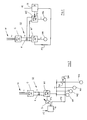
- FIG. 2 shows a circuit diagram for a spinning machine,
- Figure 3 shows another variant of the circuit of the individual motors and
- Figure 4 is a speed-time diagram showing various ways to carry out the proposed operating method.
In Figur 1 werden Spindeln S1 über ein Getriebe GE1 von einer Antriebseinrichtung M1 angetrieben. Die Antriebseinrichtung M1 kann im einfachsten Fall ein drehzahlgesteuerter, elektrischer Spindelmotor sein. Eine Welle WE kann zu einem Getriebe GE2 und dieses zu einem Vorgelegegetriebe V führen, das mit einem Getriebe GE für das Streckwerk S4 verbunden ist. Im Vorgelegegetriebe V können unterschiedliche Abtriebsdrehzahlen für das Getriebe GE gewählt werden. Alternativ zum Antrieb des Streckwerks S4 über die Welle WE und das Vorgelegegetriebe V kann auch direkt ein Streckwerksmotor M4, z.B. ein Synchronmotor, angeordnet sein. Der Spindelmotor M1 und der Streckwerksmotor M4 bzw. das Vorgelegegetriebe V sind mit einem Regler R verbunden, der die Sollfrequenzen FS für den Spindelmotor M1 und die Sollfrequenz FS' für den Streckwerksmotor M4 über Verbindungsleitungen zwischen Regler und Spindelmotor M1 bzw. Streckwerksmotor M4 vorgibt. Eine Verbindungsleitung zwischen dem Regler R und dem Vorlegegetriebe V übermittelt gegebenenfalls die vorgegebene Schaltfunktion FS" für das Vorlegegetriebe. Der Regler erhält die vorgebenen Programme für das Absenken der Drehzahl des Spindelmotors M1, des Streckwerkmotors M4 bzw. für die Schaltfunktion FS" des Vorlegegetriebes V von einem Programmspeicher P. Je nach Garn, das in der Spinnmaschine herzustellen ist, können verschiedene Programme abgerufen werden.In FIG. 1, spindles S1 are driven by a drive device M1 via a gear GE1. In the simplest case, the drive device M1 can be a speed-controlled, electrical spindle motor. A shaft WE can lead to a transmission GE2 and this to a countershaft transmission V, which is connected to a transmission GE for the drafting device S4. In the countershaft transmission V, different output speeds can be selected for the GE transmission. As an alternative to driving the S4 drafting system via the shaft WE and the countershaft transmission V, a M4 drafting system motor, e.g. a synchronous motor. The spindle motor M1 and the drafting gear motor M4 or the countershaft transmission V are connected to a controller R, which specifies the target frequencies FS for the spindle motor M1 and the target frequency FS 'for the drafting gear motor M4 via connecting lines between controller and spindle motor M1 or drafting gear motor M4. A connecting line between the controller R and the countershaft transmission V may transmit the specified switching function FS "for the countershaft transmission. The controller receives the specified programs for lowering the speed of the spindle motor M1, the drafting gear motor M4 or for the switching function FS" of the countershaft transmission V von a program memory P. Depending on the yarn to be produced in the spinning machine, various programs can be called up.
In Figur 2 steuert ein Regler R über einen Sollwertgeber S, dem er die Sollfrequenz FS übermittelt, einen Wechselrichter W1, der an Motoren M1...M4 Wechselstrom liefert. Der Wechselrichter W1 wird über einen Gleichrichter G und einen Gleichspannungszwischenkreis GZ mit Gleichstrom versorgt. Im Gleichspannungszwischenkreis GZ kann ein Kondensator K angeordnet sein, der beim Herunterfahren der Spinnmaschine über den Wechselrichter W1 zurückgespeiste elektrische Energie aufnehmen kann. Der Gleichrichter G wird von einer Wechselspannungsquelle W im Regelfall mit 3-Phasen-Wechselstrom versorgt. Zwischen Wechselrichter W1 und Streckwerksmotor M4 sitzt ein Schalter SA, der Streckwerksmotor M4 eingeschaltet werden kann. Für das Umschalten ist ein Stellmotor SM vorgesehen, wobei die Schaltfunktion FS" vom Regler R übermittelt wird. Im Normalbetrieb der Spinnmaschine wird nun beispielsweise mit konstanter Sollfrequenz FS' gefahren, so dass der Zustand des Sollwertgebers S unverändert bleibt. Die Schaltfunktion FS" des Schalters SA bleibt ebenfalls unverändert, beispielsweise in Stellung zwischen Frequenzteiler T4 und Streckwerksmotor M4. Wenn der Regler einen Abstellimpuls AI beispielsweise von einer Bedienungsstation empfängt, wird die Sollfrequenz FS des Wechselrichters W1 über den Sollwertgeber S erniedrigt. Dadurch werden die Motoren M1...M4 abgebremst. Würde der Schalter SA nun in der ursprünglichen Stellung beim Frequenzteiler T4 bleiben, würden die Drehzahlen des Spindelmotors M1 und des Streckwerkmotors M4 in einem festen Verhältnis reduziert werden. Durch Unterbrechung der Stromzufuhr zum Streckwerkmotor M4 kann nun während des Absenkens des allgemeinen Drehzahlniveaus in der Spinnmaschine die Antriebsgeschwindigkeit im Streckwerk S4 früher und stärker als im Spindelantrieb reduziert werden. Die Motoren M1 bis M4 werden bevorzugt als Synchronmotoren ausgeführt.In FIG. 2, a controller R controls, via a setpoint generator S, to which it transmits the setpoint frequency FS, an inverter W1, which supplies alternating current to motors M1 ... M4. The inverter W1 is about a rectifier G and a DC voltage intermediate circuit GZ with direct current. A capacitor K can be arranged in the DC voltage intermediate circuit GZ and can absorb electrical energy fed back via the inverter W1 when the spinning machine is shut down. The rectifier G is usually supplied by an AC voltage source W with 3-phase AC. A switch SA is located between the inverter W1 and the drafting motor M4 and the drafting motor M4 can be switched on. A servomotor SM is provided for the changeover, the switching function FS "being transmitted by the controller R. In normal operation of the spinning machine, operation is now carried out, for example, at a constant setpoint frequency FS ', so that the state of the setpoint generator S remains unchanged. The switch function FS" of the switch SA also remains unchanged, for example in the position between the frequency divider T4 and the drafting motor M4. When the controller receives a shutdown pulse AI, for example from an operator station, the setpoint frequency FS of the inverter W1 is lowered via the setpoint generator S. As a result, motors M1 ... M4 are braked. If the switch SA now remained in the original position with the frequency divider T4, the speeds of the spindle motor M1 and the drafting motor M4 would be reduced in a fixed ratio. By interrupting the power supply to the drafting system motor M4, the drive speed in the drafting arrangement S4 can now be reduced earlier and more than in the spindle drive while the general speed level is being reduced in the spinning machine. The motors M1 to M4 are preferably designed as synchronous motors.
Gemäss Figur 3 ist ebenso wie gemäss Figur 2 ein Gleichrichter G an eine Wechselspannungsquelle W angeschlossen. Im Gleichstromzwischenkreis GZ ist neben dem Wechselrichter W1 für den Spindelmotor M1 ein zweiter Wechselrichter W2 für den Streckwerksmotor M4 angeschlossen. Der Regler R, bei dem der Programmspeicher P als Bestandteil dargestellt ist, steuert beide Wechselrichter W1 und W2, indem er über Verbindungsleitungen die Sollfrequenzen FS bzw. FS' übermittelt. Wenn der Regler R einen Abstellimpuls AI empfängt, wird programmgemäss zunächst die Sollfrequenz FS' im Wechselrichter W2 abgesenkt, während die Sollfrequenz FS des Wechselrichter W1 erst zu einem späteren Zeitpunkt reduziert wird. Diese Betriebsart ist wie einleitend beschrieben für schwachgedrehtes Garn vorzuziehen. Bei stärker gedrehtem Garn kann es zweckmässig sein, zunächst die Sollfrequenz FS und später erst die Sollfrequenz FS' zu reduzieren. Der Programmspeicher P muss so ausgelegt sein, dass an der Spinnmaschine auf einfache Weise Programmänderungen durchgeführt werden können, wenn dies bei Umstellung auf ein anderes herzustellendes Garn erforderlich ist.According to FIG. 3, as in FIG. 2, a rectifier G is connected to an AC voltage source W. In addition to the inverter W1 for the spindle motor M1, a second inverter W2 for the drafting motor M4 is connected in the DC intermediate circuit GZ. The controller R, in which the program memory P is shown as a component, controls both inverters W1 and W2 by transmitting the set frequencies FS or FS 'via connecting lines. When the controller R receives a shutdown pulse AI, the target frequency FS 'in the inverter W2 is first lowered, while the target frequency FS of the inverter W1 is only reduced at a later point in time. This operating mode is preferable for weakly twisted yarn as described in the introduction. In the case of a more twisted yarn, it may be expedient to first reduce the target frequency FS and only later the target frequency FS '. The program memory P must be designed in such a way that program changes can be carried out in a simple manner on the spinning machine if this is necessary when changing over to another yarn to be produced.
Die verschiedenen Möglichkeiten zur Durchführung des Betriebsverfahrens werden nachfolgend anhand der Figur 4 erläutert. Die Ordinate im Diagramm zeigt Drehzahlen N, in Richtung der Abszisse läuft die Zeit T. Die Spindeldrehzahl ist mit NSA bzw. NSB bezeichnet, während die Streckwerksdrehzahl die Bezeichnungen NW1, NW2, NW3 je nach Programm trägt. Bei einer Spinnmaschine nach dem Stand der Technik wird bspw. zum Zeitpunkt TA3 aufgrund eines Abstellimpulses AI die Spindelwellendrehzahl NSB vom Punkt C ab kontinuierlich über den Punkt D bis zum Punkt E, zum Stillstand, abgesenkt. Gleichzeitig sinkt die Streckwerkswellendrehzahl NW3 vom Punkt H über Punkt O proportional zur Spindelwellendrehzahl NSA. Mit TG ist ein Zeitpunkt gekennzeichnet, von dem ab die Drehzahl stärker als vorher abgesenkt wird.The various options for carrying out the operating method are explained below using FIG. 4. The ordinate in the diagram shows speed N, time T runs in the direction of the abscissa. The spindle speed is designated NSA or NSB, while the drafting device speed is designated NW1, NW2, NW3 depending on the program. In a spinning machine according to the prior art, for example, at time TA3, the spindle shaft speed NSB is continuously reduced from point C to point D to point E, to a standstill, due to a shutdown pulse AI. At the same time, the drafting unit shaft speed NW3 drops from point H via point O in proportion to the spindle shaft speed NSA. TG indicates a point in time from which the speed is reduced more than before.
Gemäss der Erfindung kann nun nach Empfang eines Abstellimpulses AI im Regler R zum Zeitpunkt TA1 die Streckwerkswellendrehzahl NW2 bereits vom Punkt H" an abgesenkt werden, während die Spindelwellendrehzahl NSB zunächst noch bis zum Zeitpunkt TA3 konstant bleibt und erst dann reduziert wird. Zwischen den Zeitpunkten TA1 und TA3, zu welchen die Drehzahlen der entsprechenden Motoren abgesenkt wird, liegt der Zeitdifferenzwert DW1.According to the invention, after receiving a shutdown pulse AI in the controller R at the time TA1, the drafting shaft speed NW2 can already be reduced from the point H ", while the spindle shaft speed NSB initially remains constant until the time TA3 and is only then reduced. Between the times TA1 and TA3, at which the speed of the corresponding motors is reduced, is the time difference value DW1.
Bei einer anderen Betriebsweise wird zum Zeitpunkt TA2 der Abstellimpuls AI im Regler R empfangen. Die Streckwerkswellendrehzahl NW2 wird dann gemäss Figur 4 sprunghaft vom Punkt H' auf den Wert beim Punkt L abgesenkt und dann kontinuierlich weiter verringert, während die Spindelwellendrehzahl NSA bis zum Punkt C noch auf der ursprünglichen Höhe gehalten wird und erst anschliessend sinkt.In another mode of operation, the shutdown pulse AI is received in controller R at time TA2. The drafting system shaft speed NW2 is then abruptly reduced from point H 'to the value at point L in accordance with FIG. 4 and then continuously reduced further, while the spindle shaft speed NSA is still kept at the original level up to point C and only then drops.
Bei einer weiteren Betriebsart werden die Drehzahlen des Spindelmotors M1 und des Streckwerksmotors M4 beim Empfang eines Abstellimpulses AI zum Zeitpunkt TA3 gleichzeitig abgesenkt, wobei die Spindelwellendrehzahl NSB über der Zeit vom Punkt C zum Punkt D läuft und die Streckwerkswellendrehzahl NW3 vom Punkt H bis zum Punkt H'" stetig abgesenkt wird. Bis zum Punkt L' wird dann der Streckwerksmotor M4 stärker gebremst, da seine Sollfrequenz FS' stärker reduziert wird, wodurch die Streckwerkswellendrehzahl NW3 auf ein tieferes Niveau NW2 beim Punkt L' abfällt. Weiterhin wird dann die Streckwerkswellendrehzahl NW2 stetig bis zum Punkt O und dann weiter bis zum Punkt E auf Null reduziert. Während mit der Schaltung nach Figur 3 alle in Figur 4 gezeigten Drehzahlverläufe gefahren werden können, kann mit dem in Fig. 1 beschriebenen Prinzip die Streckwerksdrehzahl NW2 nur sprunghaft geändert werden, vgl. Linienzug H"-H'-L. Bei Betätigung des Schalters SA gemäss Fig. 2 in die Unterbrechungsstellung läuft das Streckwerk gemäss Linienzug NW3 über die Punkte H-O'-E' früher aus als die Spindeln.In a further operating mode, the speeds of the spindle motor M1 and the drafting motor M4 are simultaneously reduced when receiving a shutdown pulse AI at the time TA3, the spindle shaft speed NSB running over time from point C to point D and the drafting shaft speed NW3 from point H to point H The drafting system motor M4 is then braked more strongly up to the point L 'because its target frequency FS' is reduced more, as a result of which the drafting device shaft speed NW3 drops to a lower level NW2 at point L '. Furthermore, the drafting device shaft speed NW2 then becomes constant reduced to zero to point O and then further to point E. While all of the speed curves shown in FIG. 4 can be run with the circuit according to FIG. 3, the drafting device speed NW2 can only be changed by leaps and bounds using the principle described in FIG Line train H "-H'-L. When the switch SA according to FIG. 2 is actuated into the interruption position, the drafting system according to line NW3 runs out earlier than the spindles via the points H-O'-E '.
Wie eingangs erwähnt, kann es auch zweckmässig sein, die Spindelwellendrehzahl NSA vor der Streckwerkswellendrehzahl zu senken. Für diesen Fall wird angenommen, dass der Abstellimpuls AI im Regler R zum Zeitpunkt TA4 empfangen wird. Die Spindelwellendrehzahl NSA wird dann vom Punkt C' ab zu den Punkten D und E abgesenkt. Erst zu einem späteren Zeitpunkt TA3 wird die Streckwerkswellendrehzahl NW3 beim Punkt H über den Punkt O ebenfalls bis auf Null beim Punkt E abgesenkt. In diesem Fall wird das Spinngarn zwischen Streckwerk S4 und Spindel S1 bis zum Stillstand der Spinnmaschine weniger gedreht, wodurch die Krangelbildung bei höher gedrehtem Garn verhindert wird.As mentioned at the beginning, it can also be expedient to lower the spindle shaft speed NSA before the drafting system shaft speed. In this case, it is assumed that the shutdown pulse AI is received in controller R at time TA4. The spindle shaft speed NSA is then lowered from point C 'to points D and E. Only at a later point in time TA3 is the drafting system shaft speed NW3 at point H, via point O, likewise reduced to zero at point E. In this case, the spinning yarn between drafting device S4 and spindle S1 is rotated less until the spinning machine comes to a standstill, thereby preventing the formation of claws when the yarn is turned higher.
- AI AbstellimpulsAI shutdown pulse
- B BatterieB battery
- C Punkte auf Linienzügen in Figur 4 Diagramm N, TC points on lines in Figure 4 diagram N, T
- DD
- E "E "
- H "H "
- L "L "
- OO
- DW1 DifferenzwertDW1 difference value
- DW2 "DW2 "
- FS SollfrequenzFS set frequency
- FS' "FS '"
- FS" SchaltfunktionFS "switching function
- FG' GrenzfrequenzFG 'cutoff frequency
- G GleichrichterG rectifier
- GE GetriebeGE gearbox
- GE1 "GE1 "
- GE2GE2
- GZ GleichspannungszwischenkreisGZ DC link
- K KondensatorK capacitor
- M1 SpindelmotorM1 spindle motor
- M4 StreckwerkmotorM4 drafting motor
- M2 ZusatzmotorM2 additional engine
- M3 "M3 "
- M Messgerät (Spannung)M measuring device (voltage)
- ML SignalleitungML signal line
- N DrehzahlN speed
- NG GrenzdrehzahlNG limit speed
- NO Ursprüngliche SpindelwellendrehzahlNO Original spindle shaft speed
- NSA SpindelwellendrehzahlNSA spindle shaft speed
- NSB "NSB "
- NSB'NSB '
- NSB"NSB "
- NW1NW1
- NW2NW2
- NW3NW3
- R ReglerR controller
- P ProgrammspeicherP program memory
- S SollwertgeberS setpoint generator
- S1 SpindelnS1 spindles
- S4 StreckwerkS4 drafting system
- SA SchalterSA switch
- SM StellmotorSM actuator
- T ZeitT time
- TX WiedereinschaltzeitTX restart time
- TA ZeitpunktTA time
- TA1TA1
- TA2TA2
- TA4 "TA4 "
- TB "TB "
- TB' "TB '"
- TG GrenzzeitTG time limit
- V Vorgelegegetriebe mit StellantriebV countershaft transmission with actuator
- WE WelleWE wave
- W WechselspannungsquelleW AC voltage source
- Wl Wechselrichter für MlWl inverter for Ml
- W2 Wechselrichter für M4W2 inverter for M4
Claims (7)
Applications Claiming Priority (2)
| Application Number | Priority Date | Filing Date | Title |
|---|---|---|---|
| CH324590 | 1990-10-09 | ||
| CH3245/90 | 1990-10-09 |
Publications (2)
| Publication Number | Publication Date |
|---|---|
| EP0480357A1 true EP0480357A1 (en) | 1992-04-15 |
| EP0480357B1 EP0480357B1 (en) | 1995-04-19 |
Family
ID=4251795
Family Applications (1)
| Application Number | Title | Priority Date | Filing Date |
|---|---|---|---|
| EP19910117075 Expired - Lifetime EP0480357B1 (en) | 1990-10-09 | 1991-10-08 | Ring spinning machine |
Country Status (2)
| Country | Link |
|---|---|
| EP (1) | EP0480357B1 (en) |
| DE (1) | DE59105248D1 (en) |
Cited By (1)
| Publication number | Priority date | Publication date | Assignee | Title |
|---|---|---|---|---|
| JP2001115343A (en) * | 1999-09-20 | 2001-04-24 | Mas Fab Rieter Ag | Ring spinning frame having clamping device in spindle |
Citations (4)
| Publication number | Priority date | Publication date | Assignee | Title |
|---|---|---|---|---|
| DE2753924A1 (en) * | 1977-12-03 | 1979-06-07 | Zinser Textilmaschinen Gmbh | Textile machine drive assembly - has separate drive motors for sets of operating members the motors having their supply frequency modulated by frequency converters |
| US4518899A (en) * | 1983-03-16 | 1985-05-21 | Zinser Textilmaschinen Gmbh | Process and apparatus for correlating startup and cutoff periods of different induction motors with one another |
| DE3822420A1 (en) * | 1988-07-02 | 1990-01-04 | Skf Textilmasch Komponenten | RING SPIDER / OR RING TWISTING MACHINE |
| EP0389118A2 (en) * | 1989-03-23 | 1990-09-26 | Hollingsworth (U.K.) Limited | Ring spinning doubling and twisted frames with switched reluctance drive spindle motor |
-
1991
- 1991-10-08 DE DE59105248T patent/DE59105248D1/en not_active Expired - Lifetime
- 1991-10-08 EP EP19910117075 patent/EP0480357B1/en not_active Expired - Lifetime
Patent Citations (4)
| Publication number | Priority date | Publication date | Assignee | Title |
|---|---|---|---|---|
| DE2753924A1 (en) * | 1977-12-03 | 1979-06-07 | Zinser Textilmaschinen Gmbh | Textile machine drive assembly - has separate drive motors for sets of operating members the motors having their supply frequency modulated by frequency converters |
| US4518899A (en) * | 1983-03-16 | 1985-05-21 | Zinser Textilmaschinen Gmbh | Process and apparatus for correlating startup and cutoff periods of different induction motors with one another |
| DE3822420A1 (en) * | 1988-07-02 | 1990-01-04 | Skf Textilmasch Komponenten | RING SPIDER / OR RING TWISTING MACHINE |
| EP0389118A2 (en) * | 1989-03-23 | 1990-09-26 | Hollingsworth (U.K.) Limited | Ring spinning doubling and twisted frames with switched reluctance drive spindle motor |
Cited By (4)
| Publication number | Priority date | Publication date | Assignee | Title |
|---|---|---|---|---|
| JP2001115343A (en) * | 1999-09-20 | 2001-04-24 | Mas Fab Rieter Ag | Ring spinning frame having clamping device in spindle |
| US6487841B1 (en) | 1999-09-20 | 2002-12-03 | Maschinenfabrik Rieter Ag | Ring spinning frame with clamping device at the spindle |
| DE10037513B4 (en) * | 1999-09-20 | 2010-09-30 | Maschinenfabrik Rieter Ag | Method for controlling a ring spinning machine and spinning machine |
| JP4638584B2 (en) * | 1999-09-20 | 2011-02-23 | マシーネンファブリク リーター アクチェンゲゼルシャフト | Ring spinning machine with clamping device on spindle |
Also Published As
| Publication number | Publication date |
|---|---|
| DE59105248D1 (en) | 1995-05-24 |
| EP0480357B1 (en) | 1995-04-19 |
Similar Documents
| Publication | Publication Date | Title |
|---|---|---|
| DE2911378C2 (en) | ||
| DE3347113C2 (en) | Spinning or twisting machine with single drive | |
| EP0451534B1 (en) | Textile machine, in particular ring spinning machine | |
| EP0094483B1 (en) | Winding spindle drive | |
| CH667884A5 (en) | DEVICE FOR OPERATING A SPINNING OR TWINING MACHINE. | |
| EP0355557A1 (en) | Textile machine with a drafting arrangement | |
| DE69932961T2 (en) | Textile machine with single spindle drive where the spindle drives are divided into modular units. | |
| DE3633627C2 (en) | Method and device for operating a machine producing textile threads and / or winding the threads on winding cores | |
| EP0349831B1 (en) | Synchronisable propulsion system | |
| EP1048769B1 (en) | Process for starting a loom with electromotive main drive | |
| EP0440025B1 (en) | Device for driving an open end spinning machine | |
| DE1685915B2 (en) | ||
| EP0480357B1 (en) | Ring spinning machine | |
| DE19821251A1 (en) | Drive system for a spinning machine with a number of spindle drive motors | |
| DE4404503A1 (en) | Rotor-spinning machine | |
| DE3741430C2 (en) | ||
| DE3324243A1 (en) | False-twist crimping machine and process for bridging brief voltage losses on textile machines | |
| DE3822358C2 (en) | ||
| DE4039086A1 (en) | Yarn winding machine - has direct wind with speed regulation in steps as the reel fills | |
| EP0155472A1 (en) | Process for controlling the drive of electrical machines | |
| EP0671355B1 (en) | Sliver stacking | |
| DE2228202A1 (en) | Single motor drive of a rotatable clamping sleeve for winding devices | |
| DE1959014A1 (en) | Textile machine with a device for evenly running out the drive motors | |
| EP1442167A1 (en) | Yarn feeding device and method for yarn feeding | |
| DE4205215A1 (en) | Ring spinner doffer - has additional motor to position doffer beam during bobbin winding to reduce doffing stoppage times |
Legal Events
| Date | Code | Title | Description |
|---|---|---|---|
| PUAI | Public reference made under article 153(3) epc to a published international application that has entered the european phase |
Free format text: ORIGINAL CODE: 0009012 |
|
| 17P | Request for examination filed |
Effective date: 19920128 |
|
| AK | Designated contracting states |
Kind code of ref document: A1 Designated state(s): CH DE FR GB IT LI |
|
| 17Q | First examination report despatched |
Effective date: 19940202 |
|
| GRAA | (expected) grant |
Free format text: ORIGINAL CODE: 0009210 |
|
| AK | Designated contracting states |
Kind code of ref document: B1 Designated state(s): CH DE FR GB IT LI |
|
| PG25 | Lapsed in a contracting state [announced via postgrant information from national office to epo] |
Ref country code: FR Effective date: 19950419 Ref country code: GB Effective date: 19950419 |
|
| REF | Corresponds to: |
Ref document number: 59105248 Country of ref document: DE Date of ref document: 19950524 |
|
| ITF | It: translation for a ep patent filed |
Owner name: GUZZI E RAVIZZA S.R.L. |
|
| EN | Fr: translation not filed | ||
| GBV | Gb: ep patent (uk) treated as always having been void in accordance with gb section 77(7)/1977 [no translation filed] |
Effective date: 19950419 |
|
| PLBE | No opposition filed within time limit |
Free format text: ORIGINAL CODE: 0009261 |
|
| STAA | Information on the status of an ep patent application or granted ep patent |
Free format text: STATUS: NO OPPOSITION FILED WITHIN TIME LIMIT |
|
| 26N | No opposition filed | ||
| PGFP | Annual fee paid to national office [announced via postgrant information from national office to epo] |
Ref country code: CH Payment date: 19960920 Year of fee payment: 6 |
|
| PG25 | Lapsed in a contracting state [announced via postgrant information from national office to epo] |
Ref country code: CH Free format text: LAPSE BECAUSE OF NON-PAYMENT OF DUE FEES Effective date: 19971031 Ref country code: LI Free format text: LAPSE BECAUSE OF NON-PAYMENT OF DUE FEES Effective date: 19971031 |
|
| REG | Reference to a national code |
Ref country code: CH Ref legal event code: PL |
|
| PGFP | Annual fee paid to national office [announced via postgrant information from national office to epo] |
Ref country code: DE Payment date: 20101022 Year of fee payment: 20 |
|
| PGFP | Annual fee paid to national office [announced via postgrant information from national office to epo] |
Ref country code: IT Payment date: 20101026 Year of fee payment: 20 |
|
| REG | Reference to a national code |
Ref country code: DE Ref legal event code: R071 Ref document number: 59105248 Country of ref document: DE |
|
| REG | Reference to a national code |
Ref country code: DE Ref legal event code: R071 Ref document number: 59105248 Country of ref document: DE |
|
| PG25 | Lapsed in a contracting state [announced via postgrant information from national office to epo] |
Ref country code: DE Free format text: LAPSE BECAUSE OF EXPIRATION OF PROTECTION Effective date: 20111009 |