EP0478130A2 - Verfahren und Vorrichtung zur Zeigerbewegungssteuerung - Google Patents
Verfahren und Vorrichtung zur Zeigerbewegungssteuerung Download PDFInfo
- Publication number
- EP0478130A2 EP0478130A2 EP91307333A EP91307333A EP0478130A2 EP 0478130 A2 EP0478130 A2 EP 0478130A2 EP 91307333 A EP91307333 A EP 91307333A EP 91307333 A EP91307333 A EP 91307333A EP 0478130 A2 EP0478130 A2 EP 0478130A2
- Authority
- EP
- European Patent Office
- Prior art keywords
- point
- segment
- cursor
- display screen
- graphics object
- Prior art date
- Legal status (The legal status is an assumption and is not a legal conclusion. Google has not performed a legal analysis and makes no representation as to the accuracy of the status listed.)
- Granted
Links
Images







Classifications
-
- G—PHYSICS
- G06—COMPUTING OR CALCULATING; COUNTING
- G06F—ELECTRIC DIGITAL DATA PROCESSING
- G06F3/00—Input arrangements for transferring data to be processed into a form capable of being handled by the computer; Output arrangements for transferring data from processing unit to output unit, e.g. interface arrangements
- G06F3/01—Input arrangements or combined input and output arrangements for interaction between user and computer
- G06F3/048—Interaction techniques based on graphical user interfaces [GUI]
- G06F3/0487—Interaction techniques based on graphical user interfaces [GUI] using specific features provided by the input device, e.g. functions controlled by the rotation of a mouse with dual sensing arrangements, or of the nature of the input device, e.g. tap gestures based on pressure sensed by a digitiser
- G06F3/0489—Interaction techniques based on graphical user interfaces [GUI] using specific features provided by the input device, e.g. functions controlled by the rotation of a mouse with dual sensing arrangements, or of the nature of the input device, e.g. tap gestures based on pressure sensed by a digitiser using dedicated keyboard keys or combinations thereof
- G06F3/04892—Arrangements for controlling cursor position based on codes indicative of cursor displacements from one discrete location to another, e.g. using cursor control keys associated to different directions or using the tab key
-
- G—PHYSICS
- G06—COMPUTING OR CALCULATING; COUNTING
- G06F—ELECTRIC DIGITAL DATA PROCESSING
- G06F3/00—Input arrangements for transferring data to be processed into a form capable of being handled by the computer; Output arrangements for transferring data from processing unit to output unit, e.g. interface arrangements
- G06F3/01—Input arrangements or combined input and output arrangements for interaction between user and computer
- G06F3/048—Interaction techniques based on graphical user interfaces [GUI]
- G06F3/0484—Interaction techniques based on graphical user interfaces [GUI] for the control of specific functions or operations, e.g. selecting or manipulating an object, an image or a displayed text element, setting a parameter value or selecting a range
- G06F3/04842—Selection of displayed objects or displayed text elements
Definitions
- the present invention relates to a method of and an apparatus for moving a cursor while constrained on the contour of a graphics object in order to permit a point on the contour of the graphics object to be easily selected in a graphics processing system including a computer.
- Processing of a graphics object displayed on a display screen is typically performed by moving a cursor.
- a user while looking at the display screen, controls the movement of the cursor by giving instructions through a cursor key or by moving a pointing device such as a mouse. Moving and positioning the cursor on a specific point on the contour of the displayed graphics object involves a difficult visual operation for the user. Moreover, this operation alone does not allow the user to select a point on the contour of the graphics object with geometrical precision; he or she can merely select a point that appears to his or her eyes to be nearest to the target graphics object.
- JA PUPA 60-168227 describes a method of and apparatus for moving a cursor to a specific position on a graphics object, in which when a user wants to select a point P on the line F shown in Figure 21 of the accompanying drawings, he first locates the cursor at an arbitrary point Q on the S-shaped curve E. This specifies the starting point for tracking. Next, the user specifies the direction in which tracking should start by moving the part for manipulation from point Q toward point P. The pixels forming the line figure are then sequentially tracked in the specified direction by a line tracking unit.
- This cursor movement control apparatus is provided with multiple predetermined masks for tracking pixels. The user can select one of the pixels being tracked.
- Tracking of pixels is continued until the user specifies that the process be terminated, that is, until a point on the line is selected. However, once the tracking has begun, the direction cannot be changed. In the example shown in Figure 21, if the cursor has passed beyond the desired point P, the user must again specify the starting point and direction of tracking in order to move the cursor back. This is difficult. Furthermore, referring to figure 22A of the accompanying drawings, segment N, which intersects segment M, cannot be tracked. More specifically, pixels are distributed as shown in Figure 22B of the accompanying drawings at the point of intersection of segments M and N. The apparatus cannot determine which of P2 and P3 should be selected as a subsequent pixel to P1.
- JA PUPA 62-242494 describes a method of and apparatus for cursor movement control in which graphics objects are treated as functions, and a point at which tracking should start is predetermined for each graphics object.
- a user specifies a graphics object
- the cursor is moved to and displayed at the starting point of tracking on the graphics object.
- the user specifies a tracking direction by means of a cursor key
- the cursor starts moving in the specified direction.
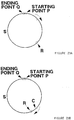
- the starting point of tracking on a circle S is fixed at point P and, when the user instructs a rightward movement, the cursor C starts moving toward a terminal point Q in the direction indicated by an arrow.
- the user must specify a point and a direction to start tracking.
- the common features of the conventional apparatuses for and methods of cursor movement control are the need to specify a tracking direction every time the user starts tracking a graphics object with a cursor and the impossibility of changing the direction once the tracking has begun. Since a point on a graphics object is selected by trial and error in most cases, repeatedly specifying the manipulation for every change in the tracking direction is a burden on the user. In addition, tracking of a graphics object is performed automatically, and the user can specify only that the process be terminated. While cursor movements other than for tracking a graphics object are controlled through a pointing device or an equivalent, tracking of a graphics object alone is outside the direct control of the user. This lacks consistency and results in bad operability.
- an apparatus for moving a cursor while constrained on a selected graphics object displayed on a display screen comprising: means for entering a signal for pointing to a position on the display screen; means for determining a point on the display screen in response to the signal entered by the means; means for determining a joint on the graphics object which is near to the point determined by the means; and means for displaying a cursor at the point determined by the means.
- a method of moving a cursor while constrained on a selected graphics object displayed on a display screen comprising:
- Steps (a) to (d) may be repeated until the user enters a signal indicating constraint release, such as an indication that a point on the graphics object has been selected.
- step (d) the cursor displayed heretofore may be deleted.
- step (d) positional information on the point determined in step (c) may be displayed.
- the signal entered in step (a) may be a signal that indicates the direction and distance of motion of a pointing device.
- the point determined in step (c) may be a projection onto the graphics object of the point determined in step (b).
- the graphics object is a simple segment
- points for dividing the segment by arbitrary ratios can readily be selected if information on the division of the segment by the point determined in step (c) is displayed in step (d).
- the segment may be virtually divided into n intervals (where n is an integer greater than 1) in response to the user's instructions, and the method may further include a step for determining representative points in the respective intervals.
- Such representative points may consist of the opposite ends of the simple segment and points that divide the segment into (n-1) equal parts.
- the point determined in step (c) may be a representative point in the interval nearest to the point determined in step (b) among the n intervals, and the cursor may be displayed at the representative point in step (d). This makes it easy to select points that divide segments into equal portions.
- a preferred example of a method according to the present invention for moving a cursor while constrained on the selected graphics object displayed on the display screen comprises the steps of: (a) entering a signal for pointing to a position on the display screen; (b) determining a segment li from the continuous series of segments displayed on the display screen and a point Qi on the display screen, in response to the signal entered in step (a); (c) determining a point Pi that is a projection of the point Qi onto the segment li; and (d) displaying a cursor at the point Pi.
- Step (b) determines whether the point at which the cursor is displayed is an end of the segment or not. If so, segment li may be selected from the segment including thE point at which the cursor is currently displayed and the segment adjacent thereto, in response to the signal entered in step (a). Otherwise, a segment including the point at which the cursor is currently displays.d is determined to be segment li.
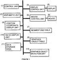
- Figure 1 is an explanatory view of the constituent components of a cursor movement control apparatuus according to the invention
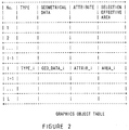
- Figure 2 is an explanatory view of a graphics object table
- Figures 3A and 3B are explanatory views of the selection effective area of a graphics object
- Figure 4 is an explanatory view of a method for selecting a graphics object
- Figure 5 is an explanatory view of the input data and output data of the apparatus of Figure 1;
- Figure 6 is a view showing the relationship between a mouse movement on a desk and the position pointed to on a display screen
- Figure 7 is a flow chart showing a method for moving a mouse cursor while constrained on a simple segment
- FIGS 8A to 8E are explanatory views of steps constituting the method of Figure 7;
- Figures 9A and 9B are explanatory views of an example for obtaining a projective point
- Figures 10A and 10B are explanatory views of a cursor movement according to the method of Figure 7;
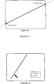
- Figure 11 is an explanatory view of a graphics object in the form of a straight line
- Figure 12 is an explanatory view of an example of the display of positional information
- Figure 13 is an explanatory view of an example of the display of segment divisional information
- Figure 14 is an explanatory view of another example of the display of segment divisional information
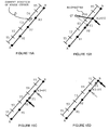
- Figures 15a to 15D are explanatory views of a discontinuous mode
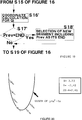
- Figure 16 is a flow chart showing a method for moving a mouse cursor while constrained on a continous series of segments
- FIGS 17A to 17F are explanatory views of steps constituting the method of Figure 16;
- Figures 18A and 18B are explanatory views of cursor movement according to the method of Figure 16;
- Figure 19 is a flow chart showing a modification of the method of Figure 16;
- Figure 20 is an explanatory view of a cursor movement on a parabola and displayed information
- Figures 21, 22a and 22B are explanatory views of an example of a conventional technique.
- Figures 23A, 23B and 24 are explanatory views of another example of a conventional technique.
- cursor movement control apparatus includes a control unit (1), arithmetic unit (2), display control unit (3), display (4), mouse control unit (5), mouse (6), segment end table (7), grapnics object table (8), position coordinate display unit (9), ratio display unit (10), data storage area (11), and graphics object selection unit (12). All the information on all graphics objects currently drawn on a display screen is stored in the graphics object table (8). The information includes the numbers of the graphics objects; types of graphic.s objects (segments, circles, points, etc.); geometrical data on graphics objects, including coordinate values, attributes such as types of lines or shapes of points; and selection effective areas, which are assorted and managed for each graphics object (see Figure 2).
- a length constant "D_LENGTH" is predetermined for each graphics object as the selection effective area.
- a graphics object is selected by locating the mouse cursor in the. selection effective area of a desired graphic object and clicking the buttom on the left. This method of selecting a graphics object is already known.
- the interior is also regarded as part of the selection effective area.
- the apparatus in Figure 1 receives signals indicating the number of a graphics object, the operating mode (coordinate display, ratio display, continuous mode, discontinuous mode, and the value of equal division n in the case of the continuous mode), the current coordinate value of the mouse cursor, and the direction and distance of motion of the mouse. It then outputs the values of the coordinates of a finally designated point on the graphics object to, for example, the data storage area (11), while displaying the cursor according to a movement of the mouse and also displaying, in a certain mode, information on the cursor display position and on the segment division.
- the operating mode coordinate display, ratio display, continuous mode, discontinuous mode, and the value of equal division n in the case of the continuous mode
- the current coordinate value of the mouse cursor and the direction and distance of motion of the mouse. It then outputs the values of the coordinates of a finally designated point on the graphics object to, for example, the data storage area (11), while displaying the cursor according to a movement of the mouse and also displaying, in a certain mode
- Figure 6 shows the relationship between the mouse moved on a desk and the position pointed to on the screen.
- the movement of the mouse on the desk is divided to small parts and thereby reduced to a series of numerous linear movements on a two-dimensional plane.
- the individual linear movements are mapped on the display screen. They are analyzed into the directions and distances moved by the mouse.
- the direction of motion B of the mouse is the direction of motion b of the mouse cursor on the display screen.
- the distance of motion a of the mouse cursor is obtained by multiplying the distance of motion A of the mouse by a certain constant ratio (mr).
- the next position of the mouse cursor is not calculated from a and b alone. This is an important feature of the present invention. Henceforth, the distance a is called to the virtal distance of motion of the mouse cursor and the direction b is called the virtual direction of motion of the mouse cursor.
- the role of the mouse control unit (5) is summarized as a) receiving a signal indicating the direction and the distance of motion by a mouse on a desk, b) displaying the mouse cursor at a designated position on the screen of the display (4) through the display control unit (3) and deleting it therefrom, and c) sensing a click of the mouse button and generating a signal indicating the current coordinate of the mouse cursor.
- the mouse control unit (5) detects a click of the left button of the mouse and the current coordinates of the cursor, and sends a signal indicating the coordinates through the control unit (1) to the graphics object selection unit (12).
- the graphics object selection unit (12) searches the graphics object table (8) and supplies the number of a graphics object having the detected coordinates within the selection effective area.
- the control unit (1) searches the graphics object table (8) for the two ends of the segment and records the coordinate value in the segment and table (7) (here the ends are named A and B, respectively, and the respectively coordinate values Xa, Ya, Xb and Yb).
- the mouse control unit (5) displays the mouse cursor, through the display control unit (3), at a point P0 (Xp0, Yp0), which is a projection onto the segment of the current position of the mouse cursor, namely, point Q0 (Xq0, Yq0).
- S5 S3 and S4 are repeated until a termination instruction (a click of the mouse button) is given, thereby obtaining Q1, P1, Q2, P2 ... in sequence and moving the mouse cursor accordingly ( Figures 8D and 8E).
- Calculation of the coordinate values of P0, P1, Q0, Q1, and so on is performed by the arithmetic unit (2) on the basis of information stored in the segment end table (7). These necessary data are temporarily recorded in the data storage area (11), and are deleted when deemed unnecessary.
- the target graphics object namely, the object to be followed by the cursor
- the coordinates of the two points at opposite ends of the visible part of the straight line or the half line on the display are calculated by referring to the graphics object table (8).
- the foregoing steps S1 to S6 are then performed, taking points A and B as the end points in the base of the above segment (see Figure 11).
- the position coordinate display unit (9) on every movement of the mouse cursor, displays new values for the coordinate of the mouse cursor on the display (4) through the display control unit (3), as shown in Figure 12.
- a function for displaying information on the division of the segment by means of the current position of the cursor may be utilized in addition to the function for displaying the values of the coordinates of the mouse cursor.
- a continuous mode and a discontinuous mode are available for displaying divisional information.
- the ratio display unit (10) displays the value of AP/AB on the screen of the display (4) through the display control unit (3), as shown in Figure 13 in the continuous mode.
- the value of the ratio is renewed for every movement of the mouse.
- the segment AB is first divided virtually into n pieces of equal parts.
- the mouse cursor can move only to a total of (n+1) points, which are located at the opposite ends A and B and at (n-1) points dividing the segment internally.
- the ratio is displayed as "i : n-1", using an integer i (0 ⁇ i ⁇ n).
- Figure 14 shows an example un which a selection is made from quadrisectional points on the segment while the ratio is displayed in the discontinuous mode.
- the boundary between intervals T1 and T2 is the mid-point of the segment AR1
- the boundary between intervals T2 and T3 is the mid-point of the segment R1R2
- the boundary between intervals T3 and T4 is the mid-point of the segment R2R3
- the boundary between intervals T4 and T5 is the mid-point of the segment R3B.
- the point nearest to the current position of the mouse cursor is selected from the five points (A, B, R1, R2 and R3) shown in Figure 15a. In this example, it is point R3.
- Point R3 is regarded as P0.
- the projection of Q1 onto the segment AB is shown at P1 ( Figure 15B).
- a target graphics object is a simple segment
- the user can designated whether the coordinate value should be displayed, whether the ratio should be displayed, if so, whether in the continuous mode or in the discontinuous mode and, if in the discontinuous mode, what should be the value n of equal division.
- an input device such as a mouse button or a keyboard may be used.
- An arrangement may be employed that is capable of switching the modes at an arbitrary point of time before the selection of a point on the graphics object. Further, the value n of equal division in the discontinuous mode may be variable.
- a curve means a continuous curve on a two-dimensional plane.
- a curve is often treated as a continuous series of serpents (a polygonal line) in a graphics processing unit for display purposes.
- the data on a curve object are represented in the graphics object table (8) as a row of coordinates of the vertices of the polygonal line.
- the target graphics object in the form of a curve is represented in the table (8) by a row of points G0(Xg0, Yg0), G1(Xg1, Yg1), ... Gi(Xgi, Ygi) on a two-dimensional plane, in other words, that the curve is approximately represented by i segments connecting two adjacent points in this row ( Figure 17A).
- S12 The segment nearest to the current position Q0 of the mouse cursor is selected. Specifically, projections of point Q0 are obtained for respective segments, and the distances between the respective projections and the point Q0 are obtained. These distances are compared with each other.
- a segment Gk-1 ⁇ Gk (1 ⁇ k ⁇ i) has been selected at random ( Figure 17B).
- S16 A test is performed to decide whether or not the point at which the cursor is currently displayed, namely, the point Prev, coincides with an end of segment Gk-1 ⁇ Gk, which is either point Gk-1 or point Gk.
- the drawing shows the test for point Gk alone for simplicity; the same test is performed for Gk-1.
- the half-line V extending horizontally and rightward from point Gk is taken as a reference line for the angle on the display screen.
- the angle ⁇ 1 defined by segment Gk ⁇ Gk+1 and reference line V and the angle ⁇ 2 defined by segment Gk ⁇ Gk-1 and reference line V are obtained by calculating inverse trigonometric functions by using the coordinates of points Gk-1, Gk and Gk+1.
- the angle ⁇ T defined by the vector T and the reference line V is also obtained by calculating the inverse trigonometric function.
- segment Gk-1 ⁇ Gk is determined to be segment li. If S17 determines that the movement is toward H2, segment Gk ⁇ Gk+1 is determined to be segment li.
- segment Gk ⁇ Gk+1 is determined to be segment li without executing S17.
- the mouse cursor moves along the continuous series of segments shown in Figure 18A, that is, while constrained on the target curve, in response to the movement of the mouse cursor. Finally, a point on the curve is selected upon entry of a termination instruction.
- S16′ The coordinates of point Qi are calculated on the basis of the vector of motion of the mouse mapped on the display screen, which was determined in S15.
- S17′ It is determined whether point Prev is an end of a segment or not. If so, point Pi is obtained, and segment li is regarded as the segment on which the mouse cursor currently rides.
- segment li is selected from two segments a and b having point Prev as their ends.
- the projections Qa and Qb of point Qi onto segments a and b are obtained, respectively, and the distances QiQa and QiQb are further obtained. If QiQa ⁇ QiQb, segment a is determined to be segment li. If QiQb ⁇ QiQa, segment b is determined to be segment li.
- the position coordinate display unit (9) displays a new coordinate value of the mouse cursor on the screen of the display (4) through the display control unit (3) on every movement in all the foregoing processes where the mouse cursor moves.
- the value of the derived function (2X-4) is also displayed, in addition to the coordinate values (X, Y).
- the target graphics object is a graph of a function on the xy plane
- a faculty for displaying, in addition to the values of coordinates, the value of a numerical expression calculated from these values may be added so as to provide a useful user interface application in a software system for learning mathematics.
- an unconstrained mode that permits movement of the mouse cursor in a conventional technique may be provided to allow a user to specify either mode before selecting a graphics object.
- the system may be so designed that the constraint mode is switched to the unconstrain-ed mode before selection of a point on a graphics object.
- a signal indicating the switch to the unconstrained mode terminates repetition of S3 and S4 in Figure 7 or repetition of S14 to S20 in Figure 16.
- a mouse is used as a pointing device.
- the present invention allows a light pen, joy stick, or other device to be used for pointing to a point on the display screen.
- the invention is applicable to a computer system with touch panel, in which a user points to a point on the display screen by pressing the panel instead of using a pointing device.
- application of the invention is not limited to the case in which a graphics object is managed as a simple segment or a continuous series of segments in a computer.
- the functional formula F(x,Y) of the circle may be registered directly in the graphics object table, or alternatively, data on the center and radius alone of the circle may be registered.
- the intersections with circle of the straight line connecting the center of the circle and point P are obtained, and whichever of the two obtained intersections is nearer to point P may be selected.
- the present invention makes it possible to track a graphics object by means of a cursor, without requiring the prior specification of points or directions for tracking. Further, it allows direct control by a user of the movement of a cursor constrained on the graphics object.
Landscapes
- Engineering & Computer Science (AREA)
- General Engineering & Computer Science (AREA)
- Theoretical Computer Science (AREA)
- Human Computer Interaction (AREA)
- Physics & Mathematics (AREA)
- General Physics & Mathematics (AREA)
- Processing Or Creating Images (AREA)
- Controls And Circuits For Display Device (AREA)
- Digital Computer Display Output (AREA)
Applications Claiming Priority (2)
| Application Number | Priority Date | Filing Date | Title |
|---|---|---|---|
| JP226812/90 | 1990-08-30 | ||
| JP2226812A JP2811501B2 (ja) | 1990-08-30 | 1990-08-30 | カーソル移動制御方法及び装置 |
Publications (3)
| Publication Number | Publication Date |
|---|---|
| EP0478130A2 true EP0478130A2 (de) | 1992-04-01 |
| EP0478130A3 EP0478130A3 (en) | 1992-09-23 |
| EP0478130B1 EP0478130B1 (de) | 1997-01-22 |
Family
ID=16850993
Family Applications (1)
| Application Number | Title | Priority Date | Filing Date |
|---|---|---|---|
| EP91307333A Expired - Lifetime EP0478130B1 (de) | 1990-08-30 | 1991-08-09 | Verfahren und Vorrichtung zur Zeigerbewegungssteuerung |
Country Status (5)
| Country | Link |
|---|---|
| US (1) | US5327528A (de) |
| EP (1) | EP0478130B1 (de) |
| JP (1) | JP2811501B2 (de) |
| CA (1) | CA2047887C (de) |
| DE (1) | DE69124324D1 (de) |
Families Citing this family (35)
| Publication number | Priority date | Publication date | Assignee | Title |
|---|---|---|---|---|
| US5398310A (en) * | 1992-04-13 | 1995-03-14 | Apple Computer, Incorporated | Pointing gesture based computer note pad paging and scrolling interface |
| US5563996A (en) * | 1992-04-13 | 1996-10-08 | Apple Computer, Inc. | Computer note pad including gesture based note division tools and method |
| US5479589A (en) * | 1993-08-04 | 1995-12-26 | Taligent, Inc. | Object-oriented system for selecting a graphic image on a display |
| US5745099A (en) * | 1995-12-18 | 1998-04-28 | Intergraph Corporation | Cursor positioning method |
| US6867790B1 (en) * | 1996-08-09 | 2005-03-15 | International Business Machines Corporation | Method and apparatus to conditionally constrain pointer movement on a computer display using visual cues, controlled pointer speed and barriers on the display which stop or restrict pointer movement |
| JPH10304234A (ja) * | 1997-04-24 | 1998-11-13 | Sony Corp | 撮像システム、及びビデオカメラ装置 |
| US6191785B1 (en) | 1997-12-02 | 2001-02-20 | International Business Machines Corporation | Method and system for dynamically manipulating values associated with graphical elements displayed within a graphical user interface |
| JP4223596B2 (ja) * | 1998-09-16 | 2009-02-12 | Hoya株式会社 | 電子内視鏡システム |
| US7098933B1 (en) * | 1999-02-24 | 2006-08-29 | Autodesk, Inc. | Acquiring and unacquiring alignment and extension points |
| US6342877B1 (en) * | 1999-06-10 | 2002-01-29 | Mitsubishi Electric Research Laboratories, Inc. | Method for constrained cursor movement |
| US6788284B1 (en) * | 2000-05-30 | 2004-09-07 | Agilent Technologies, Inc. | Devices, systems and methods for position-locking cursor on display device |
| US6693653B1 (en) * | 2000-09-19 | 2004-02-17 | Rockwell Collins, Inc. | Method of assisting cursor movement toward a nearby displayed target |
| US6965369B2 (en) * | 2002-02-11 | 2005-11-15 | Microsoft Corporation | Method and apparatus for smoothing cursor movement in relation to a refresh rate of a display |
| US20020171688A1 (en) * | 2002-06-12 | 2002-11-21 | Koncelik Lawrence J. | Computer mouse with cursor placement device |
| US20040113931A1 (en) * | 2002-12-05 | 2004-06-17 | Anderson Thomas G. | Human-computer interfaces incorporating haptics and path-based interaction |
| KR100940207B1 (ko) * | 2003-12-30 | 2010-02-10 | 삼성전자주식회사 | 마우스 포인팅 방법 및 제어 장치 |
| WO2005119356A2 (en) | 2004-05-28 | 2005-12-15 | Erik Jan Banning | Interactive direct-pointing system and calibration method |
| FR2875320A1 (fr) * | 2004-09-15 | 2006-03-17 | France Telecom | Procede et systeme d'identification d'un objet dans une photo, programme, support d'enregistement, terminal et serveur pour la mise en oeuvre du systeme |
| US9285897B2 (en) | 2005-07-13 | 2016-03-15 | Ultimate Pointer, L.L.C. | Easily deployable interactive direct-pointing system and calibration method therefor |
| TWI406153B (zh) * | 2007-06-12 | 2013-08-21 | Quanta Comp Inc | 游標控制方法及應用該游標控制方法之簡報系統及電腦可讀取儲存媒體 |
| US9360985B2 (en) | 2007-06-27 | 2016-06-07 | Scenera Technologies, Llc | Method and system for automatically linking a cursor to a hotspot in a hypervideo stream |
| US9141258B2 (en) * | 2007-09-18 | 2015-09-22 | Scenera Technologies, Llc | Method and system for automatically associating a cursor with a hotspot in a hypervideo stream using a visual indicator |
| US20090077459A1 (en) * | 2007-09-19 | 2009-03-19 | Morris Robert P | Method And System For Presenting A Hotspot In A Hypervideo Stream |
| US9442623B2 (en) * | 2008-06-19 | 2016-09-13 | Adobe Systems Incorporated | Guide line snapping |
| US8681106B2 (en) * | 2009-06-07 | 2014-03-25 | Apple Inc. | Devices, methods, and graphical user interfaces for accessibility using a touch-sensitive surface |
| AU2012200073B2 (en) * | 2009-06-07 | 2013-07-18 | Apple Inc. | Devices, methods, and graphical user interfaces for accessibility using a touch-sensitive surface |
| US8707195B2 (en) | 2010-06-07 | 2014-04-22 | Apple Inc. | Devices, methods, and graphical user interfaces for accessibility via a touch-sensitive surface |
| US8751971B2 (en) | 2011-06-05 | 2014-06-10 | Apple Inc. | Devices, methods, and graphical user interfaces for providing accessibility using a touch-sensitive surface |
| DE112012003889T5 (de) * | 2011-10-11 | 2014-06-05 | International Business Machines Corporation | Verfahren, Vorrichtung und Computerprogramm, die zum Zeigen auf ein Objekt dienen |
| US8881269B2 (en) | 2012-03-31 | 2014-11-04 | Apple Inc. | Device, method, and graphical user interface for integrating recognition of handwriting gestures with a screen reader |
| JP5949203B2 (ja) * | 2012-06-21 | 2016-07-06 | 富士通株式会社 | 変更プログラム、変更方法、および変更装置 |
| EP3517894B1 (de) * | 2018-01-25 | 2021-08-25 | Nokia Technologies Oy | Linienmanipulation zur wegplanung |
| US11182073B2 (en) * | 2018-11-28 | 2021-11-23 | International Business Machines Corporation | Selection on user interface based on cursor gestures |
| CN111666019B (zh) * | 2019-03-05 | 2022-01-25 | 台达电子工业股份有限公司 | 电子装置及选取目标物件的预测方法 |
| JP7555012B2 (ja) * | 2020-02-18 | 2024-09-24 | パナソニックIpマネジメント株式会社 | 計測方法及び計測装置 |
Family Cites Families (8)
| Publication number | Priority date | Publication date | Assignee | Title |
|---|---|---|---|---|
| JPS60168227A (ja) * | 1984-02-13 | 1985-08-31 | Fujitsu Ltd | 線図形追跡装置 |
| JPS60242494A (ja) * | 1984-05-11 | 1985-12-02 | 株式会社日立製作所 | カ−ソル表示位置制御装置 |
| US4698625A (en) * | 1985-05-30 | 1987-10-06 | International Business Machines Corp. | Graphic highlight adjacent a pointing cursor |
| US4742473A (en) * | 1985-07-16 | 1988-05-03 | Shugar Joel K | Finite element modeling system |
| JPS62242494A (ja) * | 1986-04-14 | 1987-10-23 | Nec Corp | 状態監視処理方式 |
| JP2642335B2 (ja) * | 1986-04-25 | 1997-08-20 | キヤノン 株式会社 | カーソル制御装置 |
| US4731609A (en) * | 1986-11-03 | 1988-03-15 | International Business Machines Corporation | Fast correlation of markers with graphic entities |
| US5159664A (en) * | 1988-07-06 | 1992-10-27 | Hitachi Ltd. | Graphic display apparatus |
-
1990
- 1990-08-30 JP JP2226812A patent/JP2811501B2/ja not_active Expired - Fee Related
-
1991
- 1991-07-25 CA CA002047887A patent/CA2047887C/en not_active Expired - Fee Related
- 1991-08-09 EP EP91307333A patent/EP0478130B1/de not_active Expired - Lifetime
- 1991-08-09 DE DE69124324T patent/DE69124324D1/de not_active Expired - Lifetime
- 1991-08-28 US US07/751,376 patent/US5327528A/en not_active Expired - Fee Related
Also Published As
| Publication number | Publication date |
|---|---|
| EP0478130B1 (de) | 1997-01-22 |
| JP2811501B2 (ja) | 1998-10-15 |
| US5327528A (en) | 1994-07-05 |
| JPH04116593A (ja) | 1992-04-17 |
| CA2047887C (en) | 1998-12-22 |
| CA2047887A1 (en) | 1992-03-01 |
| EP0478130A3 (en) | 1992-09-23 |
| DE69124324D1 (de) | 1997-03-06 |
Similar Documents
| Publication | Publication Date | Title |
|---|---|---|
| EP0478130B1 (de) | Verfahren und Vorrichtung zur Zeigerbewegungssteuerung | |
| US6801217B2 (en) | Determining and displaying geometric relationship between objects in a computer-implemented graphics system | |
| EP1046137B1 (de) | Verfahren und gerät zum vereinfachen der navigation in dreidimensionalen grafischen szenen | |
| US5757358A (en) | Method and apparatus for enhancing computer-user selection of computer-displayed objects through dynamic selection area and constant visual feedback | |
| EP0509839B1 (de) | Digitales karthographisches System zur Verarbeitung von geographischen Informationen | |
| US5812142A (en) | Motion movement cueing through synchronized display port and image | |
| US5557714A (en) | Method and system for rotating a three-dimensional model about two orthogonal axes | |
| EP0740246A2 (de) | Analytische Datenanzeigemethode und Gerät | |
| WO2008084437A1 (en) | Method and apparatus for providing an undo/redo mechanism | |
| GB2239773A (en) | Graphical object, e.g. cursor, is rotated during translation | |
| US20020180809A1 (en) | Navigation in rendered three-dimensional spaces | |
| US5815150A (en) | Display apparatus | |
| US20060017725A1 (en) | Information processing method and information processing apparatus | |
| JPH09190551A (ja) | 3次元形状の作図方法 | |
| JPH0212516A (ja) | 実寸表示方式 | |
| US6392648B1 (en) | Three dimensional graphical display generating system and method | |
| JPH1097646A (ja) | 三次元空間表示システムにおける三次元空間座標値の取得方法および装置 | |
| JPH0546311A (ja) | マウスポインテイング動作制御方式 | |
| JPH07225859A (ja) | オブジェクト表示装置 | |
| CN109240578A (zh) | 一种参数调节方法和装置 | |
| JP3060113B2 (ja) | コマンド表示選択装置 | |
| JP2610832B2 (ja) | 画面分割パターン登録方式 | |
| JPS6155728A (ja) | 座標入力装置 | |
| Grimm et al. | The ibar: A perspective-based camera widget | |
| AU753750B2 (en) | Three dimensional graphical display generating system and method |
Legal Events
| Date | Code | Title | Description |
|---|---|---|---|
| PUAI | Public reference made under article 153(3) epc to a published international application that has entered the european phase |
Free format text: ORIGINAL CODE: 0009012 |
|
| AK | Designated contracting states |
Kind code of ref document: A2 Designated state(s): DE FR GB IT |
|
| PUAL | Search report despatched |
Free format text: ORIGINAL CODE: 0009013 |
|
| 17P | Request for examination filed |
Effective date: 19920619 |
|
| AK | Designated contracting states |
Kind code of ref document: A3 Designated state(s): DE FR GB IT |
|
| 17Q | First examination report despatched |
Effective date: 19950627 |
|
| GRAG | Despatch of communication of intention to grant |
Free format text: ORIGINAL CODE: EPIDOS AGRA |
|
| GRAH | Despatch of communication of intention to grant a patent |
Free format text: ORIGINAL CODE: EPIDOS IGRA |
|
| GRAH | Despatch of communication of intention to grant a patent |
Free format text: ORIGINAL CODE: EPIDOS IGRA |
|
| GRAA | (expected) grant |
Free format text: ORIGINAL CODE: 0009210 |
|
| AK | Designated contracting states |
Kind code of ref document: B1 Designated state(s): DE FR GB IT |
|
| PG25 | Lapsed in a contracting state [announced via postgrant information from national office to epo] |
Ref country code: IT Free format text: LAPSE BECAUSE OF FAILURE TO SUBMIT A TRANSLATION OF THE DESCRIPTION OR TO PAY THE FEE WITHIN THE PRESCRIBED TIME-LIMIT;WARNING: LAPSES OF ITALIAN PATENTS WITH EFFECTIVE DATE BEFORE 2007 MAY HAVE OCCURRED AT ANY TIME BEFORE 2007. THE CORRECT EFFECTIVE DATE MAY BE DIFFERENT FROM THE ONE RECORDED. Effective date: 19970122 Ref country code: FR Effective date: 19970122 |
|
| REF | Corresponds to: |
Ref document number: 69124324 Country of ref document: DE Date of ref document: 19970306 |
|
| PG25 | Lapsed in a contracting state [announced via postgrant information from national office to epo] |
Ref country code: DE Effective date: 19970423 |
|
| EN | Fr: translation not filed | ||
| PLBE | No opposition filed within time limit |
Free format text: ORIGINAL CODE: 0009261 |
|
| STAA | Information on the status of an ep patent application or granted ep patent |
Free format text: STATUS: NO OPPOSITION FILED WITHIN TIME LIMIT |
|
| 26N | No opposition filed | ||
| PGFP | Annual fee paid to national office [announced via postgrant information from national office to epo] |
Ref country code: GB Payment date: 19990728 Year of fee payment: 9 |
|
| PG25 | Lapsed in a contracting state [announced via postgrant information from national office to epo] |
Ref country code: GB Free format text: LAPSE BECAUSE OF NON-PAYMENT OF DUE FEES Effective date: 20000809 |
|
| GBPC | Gb: european patent ceased through non-payment of renewal fee |
Effective date: 20000809 |