EP0477650A2 - Seitenkanalgebläse - Google Patents
Seitenkanalgebläse Download PDFInfo
- Publication number
- EP0477650A2 EP0477650A2 EP91115274A EP91115274A EP0477650A2 EP 0477650 A2 EP0477650 A2 EP 0477650A2 EP 91115274 A EP91115274 A EP 91115274A EP 91115274 A EP91115274 A EP 91115274A EP 0477650 A2 EP0477650 A2 EP 0477650A2
- Authority
- EP
- European Patent Office
- Prior art keywords
- vortex flow
- casing
- flow blower
- passageway
- blower according
- Prior art date
- Legal status (The legal status is an assumption and is not a legal conclusion. Google has not performed a legal analysis and makes no representation as to the accuracy of the status listed.)
- Granted
Links
Images


Classifications
-
- F—MECHANICAL ENGINEERING; LIGHTING; HEATING; WEAPONS; BLASTING
- F04—POSITIVE - DISPLACEMENT MACHINES FOR LIQUIDS; PUMPS FOR LIQUIDS OR ELASTIC FLUIDS
- F04D—NON-POSITIVE-DISPLACEMENT PUMPS
- F04D29/00—Details, component parts, or accessories
- F04D29/66—Combating cavitation, whirls, noise, vibration or the like; Balancing
-
- F—MECHANICAL ENGINEERING; LIGHTING; HEATING; WEAPONS; BLASTING
- F04—POSITIVE - DISPLACEMENT MACHINES FOR LIQUIDS; PUMPS FOR LIQUIDS OR ELASTIC FLUIDS
- F04D—NON-POSITIVE-DISPLACEMENT PUMPS
- F04D29/00—Details, component parts, or accessories
- F04D29/05—Shafts or bearings, or assemblies thereof, specially adapted for elastic fluid pumps
- F04D29/056—Bearings
- F04D29/059—Roller bearings
-
- F—MECHANICAL ENGINEERING; LIGHTING; HEATING; WEAPONS; BLASTING
- F04—POSITIVE - DISPLACEMENT MACHINES FOR LIQUIDS; PUMPS FOR LIQUIDS OR ELASTIC FLUIDS
- F04D—NON-POSITIVE-DISPLACEMENT PUMPS
- F04D23/00—Other rotary non-positive-displacement pumps
- F04D23/008—Regenerative pumps
-
- F—MECHANICAL ENGINEERING; LIGHTING; HEATING; WEAPONS; BLASTING
- F04—POSITIVE - DISPLACEMENT MACHINES FOR LIQUIDS; PUMPS FOR LIQUIDS OR ELASTIC FLUIDS
- F04D—NON-POSITIVE-DISPLACEMENT PUMPS
- F04D25/00—Pumping installations or systems
- F04D25/02—Units comprising pumps and their driving means
- F04D25/06—Units comprising pumps and their driving means the pump being electrically driven
-
- F—MECHANICAL ENGINEERING; LIGHTING; HEATING; WEAPONS; BLASTING
- F04—POSITIVE - DISPLACEMENT MACHINES FOR LIQUIDS; PUMPS FOR LIQUIDS OR ELASTIC FLUIDS
- F04D—NON-POSITIVE-DISPLACEMENT PUMPS
- F04D25/00—Pumping installations or systems
- F04D25/02—Units comprising pumps and their driving means
- F04D25/08—Units comprising pumps and their driving means the working fluid being air, e.g. for ventilation
- F04D25/082—Units comprising pumps and their driving means the working fluid being air, e.g. for ventilation the unit having provision for cooling the motor
-
- F—MECHANICAL ENGINEERING; LIGHTING; HEATING; WEAPONS; BLASTING
- F04—POSITIVE - DISPLACEMENT MACHINES FOR LIQUIDS; PUMPS FOR LIQUIDS OR ELASTIC FLUIDS
- F04D—NON-POSITIVE-DISPLACEMENT PUMPS
- F04D29/00—Details, component parts, or accessories
- F04D29/40—Casings; Connections of working fluid
- F04D29/42—Casings; Connections of working fluid for radial or helico-centrifugal pumps
- F04D29/44—Fluid-guiding means, e.g. diffusers
- F04D29/441—Fluid-guiding means, e.g. diffusers especially adapted for elastic fluid pumps
-
- F—MECHANICAL ENGINEERING; LIGHTING; HEATING; WEAPONS; BLASTING
- F04—POSITIVE - DISPLACEMENT MACHINES FOR LIQUIDS; PUMPS FOR LIQUIDS OR ELASTIC FLUIDS
- F04D—NON-POSITIVE-DISPLACEMENT PUMPS
- F04D29/00—Details, component parts, or accessories
- F04D29/58—Cooling; Heating; Diminishing heat transfer
- F04D29/5806—Cooling the drive system
-
- F—MECHANICAL ENGINEERING; LIGHTING; HEATING; WEAPONS; BLASTING
- F04—POSITIVE - DISPLACEMENT MACHINES FOR LIQUIDS; PUMPS FOR LIQUIDS OR ELASTIC FLUIDS
- F04D—NON-POSITIVE-DISPLACEMENT PUMPS
- F04D29/00—Details, component parts, or accessories
- F04D29/58—Cooling; Heating; Diminishing heat transfer
- F04D29/582—Cooling; Heating; Diminishing heat transfer specially adapted for elastic fluid pumps
- F04D29/5826—Cooling at least part of the working fluid in a heat exchanger
-
- F—MECHANICAL ENGINEERING; LIGHTING; HEATING; WEAPONS; BLASTING
- F04—POSITIVE - DISPLACEMENT MACHINES FOR LIQUIDS; PUMPS FOR LIQUIDS OR ELASTIC FLUIDS
- F04D—NON-POSITIVE-DISPLACEMENT PUMPS
- F04D29/00—Details, component parts, or accessories
- F04D29/58—Cooling; Heating; Diminishing heat transfer
- F04D29/582—Cooling; Heating; Diminishing heat transfer specially adapted for elastic fluid pumps
- F04D29/584—Cooling; Heating; Diminishing heat transfer specially adapted for elastic fluid pumps cooling or heating the machine
-
- F—MECHANICAL ENGINEERING; LIGHTING; HEATING; WEAPONS; BLASTING
- F04—POSITIVE - DISPLACEMENT MACHINES FOR LIQUIDS; PUMPS FOR LIQUIDS OR ELASTIC FLUIDS
- F04D—NON-POSITIVE-DISPLACEMENT PUMPS
- F04D29/00—Details, component parts, or accessories
- F04D29/66—Combating cavitation, whirls, noise, vibration or the like; Balancing
- F04D29/661—Combating cavitation, whirls, noise, vibration or the like; Balancing especially adapted for elastic fluid pumps
Definitions
- the present invention relates vortex flow blower and, more particularly, to a construction thereof enabling ease of handling and improved operation.
- Conventional apparatus are constituted such that, as disclosed in Japanese Utility Model Laid-Open Application No. 49-130406, an electric motor is provided in a spaced relationship from a fan casing and a location therebetween is used as a ventilating passageway for enabling windings and bearings of the electric motor to be cooled.
- a conventional vortex pump has around an inlet port, as disclosed, for example, in Japanese Patent Publication Application No. 46-33658, a construction such that the sectional area in the neighborhood of such inlet port is made greater than the sectional area of an intermediate portion of an annular groove so as to only reduce the resistance of a flow passageway to wind or air.
- a conventional vortex flow blower also utilizes a conventional silencer or muffler installed at each of an inlet port and an outlet port and a high pitch sound diffusing porous tube is built in the inside of each of the silencers as disclosed, for example, in the Official Gazette of Japanese Utility Model Laid-Open Application No. 56-109690. Furthermore, another structure is disclosed in the Official Gazette of Japanese Laid-Open Application No. 58-4795 wherein a silencer constituted from a tubular case is provided at an exhaust port of a blower and a tubular silencing material having a heat insulating property is provided on an inner periphery of the case. Also, is it known to frequently use an expansion type silencer and a branch type silencer as silencers for an automobile.
- a conventional vortex blower utilized as a centrifugal pump includes a silencer or muffler casing having shape equal or similar to a rectangular parallepiped to provide a volume for deadening noise, and with sidewalls rising straight from its base, as shown in Japanese Patent Application Laid-Open No. 52600/1981.
- the prior art described above does not pay any attention to reduction in size and mass productivity of the vortex flow blower, and since an electric motor casing and a blower casing are coupled to each other by a coupling arrangement with a spacing left therebetween and with a heat insulating wall is disposed therebetween, there are problems that the dimensions of the vortex flow blower (particularly the dimension along a direction of the shaft of the rotor of the electric motor) are increased, that the number of parts is great, and that the means productivity ability is lowered. Further, since the number of parts is great the number of operation steps in assembly is great such that the quality is not uniform and reliability is low because high accuracy in assembly is not attained.
- Factors resulting in production of noises by a vortex flow blower include (a) collision noises at an outlet port, (b) collision noises between a whirling flow in a casing flow passageway and a front edge of a vane of the impeller, (c) expansion noises and mixing noises at an inlet port, (d) disorder noises during whirling of a whirling flow, and so forth.
- the production amount of noise of (a) and (b) is much greater than the production amount of (c) and (d), and in order to reduce noise, it is important to reduce (a) and (b) or reduce noise by a silencer.
- a relative flow wi upon flowing into vanes of the impeller is experimentally determined from a flowing-in flow (absolute flow) ci of air into the vanes and a vane circumferential speed us, then the relative flow w i is about 2.5 times the vane circumferential speed ui and is a very high flowing speed. Due to such flowing in speed we, disorders are produced by flowing-in to front edges of the vanes, and thus lower the efficiency of the vortex flow blower and produces noises.
- the relationship between noises of a vortex flow blower and an inlet flow rate has such a characteristic that, as the flow rate increases, noises are decreased and the noise level is highest at a point of cut-off.
- the noise level at an operating point of the vortex flow blower is high, and, for example, where the power of the shaft of a motor is on the order of 400W, the noise level is about 85 to 95 dB (without a silencer) and is therefore high. Additionally, the noise characteristic in this instance is such that a dominant sound pressure level, like a chimney, is exhibited at a frequency (rotational noise) of [vane number x rotational speed] at which noises of a
- a silencer is provided at each of the inlet side and the outlet side, and the effect of the silencers is that, where the silencers for both of the inlet side and the outlet side are provided, the noise level is reduced to about 65 to 70 dB, but rotational noises of [vane number x rotational speed] still remain dominantly like a chimney and have a shrill disagreeable tone. Thus, reduction of such rotational noises is desired.
- a vortex flow blower includes a blower casing having an annular flow passageway from an inlet port to an outlet port disposed adjacent to the inlet port, an impeller accommodated in the blower casing for producing vortex flows in the annular flow passageway, a driver for the impeller, and a cooling passageway is provided between the inlet port and the outlet port.
- the impeller accommodated in the blower casing is driven by the driver to rotate the impeller so that air taken in from the inlet port is pressurized and discharged from the outlet port.
- the cooling passageway is provided between the inlet port and the outlet port and cools the outlet port at which the temperature becomes high due to adiabatic compression while thermally isolating the outlet port and the inlet port from each other. Consequently, high temperature air can be cooled and heat transmission from discharged air to intake air can be decreased so that a temperature rise of the vortex flow blower can be restricted.
- a vortex flow blower utilized as a flow pump including an electric motor accommodated in a motor casing, an impeller connected to the electric motor and accommodated in a blower casing,and a silencer casing securely mounted at an inlet port and an outlet port of the blower casing and extending along an axial direction of the electric motor, is constructed so that the motor casing and the silencer casing are arranged in parallel to each other and are formed in an integral relationship with the blower casing.
- the silencer casing is disposed such that an end face thereof remote from the blower casing is either disposed flush with an end face of the motor casing which is remote from the blower casing or slightly displaced toward the blower casing from the end face of the motor casing.
- the vortex flow pump has a gap provided between the motor casing and the silencer casing.
- first heat radiating fins are provided on an outer periphery of the blower casing and second heat radiating fins are provided on an outer periphery of the motor casing, the first and second fins formed continuously in an integral relationship with each other.
- the blower casing, motor casing and silencer casing are formed in an integral relationship with one another, the number of parts of the vortex flow blower is decreased and the number of operation steps in effecting coupling therebetween is decreased. Further, the positional relationship among the blower casing, motor casing and silencer casing can always be kept constant, and the uniformity of quality can be achieved. Also, the gap provided between the motor casing and the silencer casing allows cooling fluid flow caused by the cooling fan for the motor to be positively taken into a surface of the motor casing, thereby to improved cooling efficiency. Additionally, since the first and second heat radiating fins are formed continuously in an integral relationship with each other, the heat radiating area is increased and an increase of the motor temperature is reduced.
- a vortex flow pump including an impeller and a blower casing for accommodating the impeller therein with an annular groove provided on the casing in a facing relationship to vanes of the impeller, a partition wall which partitions part of a circumference of the annular groove, and an inlet port and an outlet port provided at the opposite end portions of the annular groove partitioned by the partition wall, is constructed so that a sectional area reducing member for reducing the sectional area of the annular groove is provided at at least one of a portion contiguous to the inlet port of the annular groove and another portion contiguous to the outlet port.
- the sectional area reducing arrangement includes a member taking different forms such as a continuous portion which continues smoothly to at least one of the portions contiguous to the inlet port and outlet port and a further portion contiguous to an intermediate portion of the annular groove.
- the sectional area reducing member may also be a guide plate which extends from an inner periphery side to an outer periphery side of the annular groove to partition the annular groove into at least two sections. Further the sectional area reducing member may be formed by projecting an inner face of the annular groove in a direction toward the impeller.
- the sectional area reducing member is formed separate from the casing and is securely mounted in the annular flow passageway.
- the sectional area reducing arrangement includes a member for adjusting an amount of movement in a direction toward the impeller and is constructed such that the sectional area of the annular flow passageway can be adjusted. Further, the annular groove is provided along an outer periphery of the impeller while the impeller is disposed for rotation in the annular groove, and the sectional area reducing arrangement is formed by projecting a side face of an inner side of the annular groove in a direction toward the impeller.
- the partition wall partitions part of the annular groove to form a flow passageway from the inlet port to the outlet port.
- the sectional area reducing arrangement provided at the portion of the annular groove contiguous to the inlet port introduces a fluid flow admitted from the inlet port such that it may pass sidewardly in the neighborhood of the impeller with certainty so that it may undergo friction with the impeller and air between the vanes uniformly with certainty. Consequently, a flow on the inlet side is likely provided with a speed from the impeller, and accordingly, the flow becomes smooth and the amount of fluid is increased.
- the sectional area reducing arrangement provided at the portion of the annular groove contiguous to the outlet port introduces an internal fluid flow discharged from the impeller and advancing along the casing into the impeller, and then the internal flow advances in a direction toward the outlet port after it has whirled and returned. Collision with the partition wall portion as a flow is prevented. Consequently, a fluid flow can be made smooth, and production of noises is reduced.
- the continuous portion provided on the sectional area reducing arrangement expands the sectional area of the flow passageway smoothly to reduce the resistance to ventilation to achieve pressure restoration in this section to increase a rise of a static pressure. Consequently, an increase of a fluid pressure can be realized.
- the guide plate partitions the inner periphery side and the outer periphery side of the annular groove so as to achieve smoothing of a fluid flow in a radial direction in addition to smoothing in a circumferential direction.
- the radiation noises from the inlet port and the outlet port are much higher than the noises (transmission noises) produced in a vane flow passageway and transmitted through a casing wall or a casing lid.
- the noise level at the front is higher by about 10 to 18 dB than that at the rear, although such values may vary depending upon the type of the blower.
- a vortex flow blower of the present invention is constructed firstly such that a pipe is inserted in the inside of an expansion type silencer filled with a sound absorption material so that the silencer is constituted as an insertion type silencer.
- a branch pipe is provided in the silencer to constitute a branch type silencer. The silencing by the insertion pipe and the branch pipe both depends upon a silencer which makes use of interference of sounds (resonance).
- a vortex flow blower of a configuration wherein a sound absorption material is filled in an expansion chamber around a ventilating passageway has such a structure that a pipe is provided at part of the ventilating passageway, according to a further feature, the lengths of the ventilating passageway and the insertion pipe in the silencer are set in accordance with producing conditions of noise (a frequency characteristic and a noise level), and noises of the vortex flow blower which are produced by whirling flows in ventilating passageways in an impeller and a casing are reduced by resistance when the sound source passes the sound absorption material.
- noise a frequency characteristic and a noise level
- a silencer of the branch type wherein a thin and short pipe is erected substantially vertically uprightly in the ventilating passageway of the silencer, and at a joining location of an air stream pipe to the branch pipe, part of sound waves produced and propagated in the vortex flow blower are reflected by the branch pipe extreme end and then returned to an entrance of the branch pipe so that at the branch pipe joining point, the sound waves returned from the branch pipe and sound waves of the air stream pipe are caused to interfere with each other.
- the branch pipe joining location is set at a position of loops of sound waves of a frequency to be reduced, and the length of the branch pipe is set so that such sound waves may be reflected by the branch pipe extreme end and the magnitude thereof may be opposite in phase at the entrance of the branch pipe (joining location). Since the position of loops of the magnitude of sound waves in the air stream pipe varies depending upon a frequency, the position of a magnitude at a frequency to be reduced is set in advance. Consequently, the magnitudes of the two sound waves are both loops and are opposite in phase, and the magnitude of the sound waves in the air stream pipe is reduced. In particular, energy of sounds of the particular frequency among the sound waves propagating in the air stream pipe is reduced on the downstream side of the joining location of the branch pipe.
- the vortex flow blower utilized as a centrifugal pump, including an impeller connected to an electric motor, a blower casing accommodating the impeller, and a silencer or muffler casing secured to the intake and discharge ports of the impeller casing and extending axially of the motor, is constructed so that the muffler casing has sidewalls each having an upstanding portion rising from the bottom of the silencer casing and having a width which is smaller than the maximum width of the blower casing, and having a bulging portion contiguous to the upstanding portion and curved outwardly from the top thereof.
- the bulging portion preferably has a lower part provided with frictional arrangement.
- the upstanding and bulging portions enable the muffler casing to have an increased volume and hold an increased amount of a noise sound or absorbing or deadening material, thereby producing an outstandingly good result of noise deadening.
- the silencer casing comprises an upstanding lower portion and an outwardly extending upper portion having a greater width, the construction facilitates the manual transportation of the pump.
- the frictional arrangement render slip-proof the lower parts of the bulging sidewall portions of the silencer casing and ensure the easier and safer manual transportation of the pump.
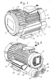
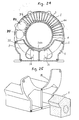
- FIGs. 1 and 2 are a front and rear perspective view of a vortex flow blower in accordance with the present invention wherein casing 2 of the motor blower includes a blower or impeller casing 3, a motor casing 4, and a silencer or muffler casing 5.
- an electric motor 30 serving as a driver has an impeller 1 of the blower connected to an end of a rotary shaft 14 4 thereof while a cooling impeller 18 is connected to the other end of the rotary shaft 14.
- the electric motor 30 includes a rotor 16 fitted on the rotary shaft 14 and a stator 17 fitted in the motor casing 4.
- the shaft 14 is supported by a radial bearing 14a provided adjacent the impeller 1 and another radial bearing 14b provided adjacent the cooling impeller 18.
- the impeller 1 is accommodated in the blower casing 3 which is provided with a cover 15.
- the blower casing 3 has an annular flow passageway 3a provided in an opposing relationship to vanes of the impeller 1 and extending from an inlet port 3b to an outlet port 3c.
- the stator 17 of the electric motor 30 When the stator 17 of the electric motor 30 is energized, the rotor 16 mounted on the rotary shaft 14 is rotated, and consequently, the impeller 1 sucks air from the inlet port 3b, pressurizes the air in the annular passageway 3a and discharges the air from the outlet port 3c.
- the silencer casing 5 for reducing noises is provided for each of the inlet port 3b and outlet port 3c.
- the blower casing 3 is formed in an integral relationship with an electric motor casing 4 and the silencer casing 5 by aluminum diecasting.
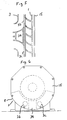
- an axial cooling ventilating passageway or gap 36 is formed between the electric motor casing and the silencer casing 5, and a radial cooling ventilating passageway 34 serving as a radially provided cooling passageway is formed between the inlet port 3b and the outlet port 3c of the blower casing 3 in a contiguous relationship to the cooling ventilating passageway 36 as shown in Fig. 5.
- External air 13 is taken into the blower by the cooling impeller or fan 18 and is advanced toward the blower casing 3 through the axial cooling ventilating passageway 36 until it comes to a location in the neighborhood of the bearing 14a adjacent the annular flow passageway, and then it changes the direction and enters the radial cooling ventilating passageway 34, whereafter it passes between the inlet port 3b and the outlet port 3c and is then discharged outside.
- Heat generation is heat the electric motor 30 generates from a portion of the blower, and discharging of heat is dominantly performed by heat transmission by ventilation wherein the cooling fan or impeller 18 and the blower impeller 1 serve as ventilation sources. Heat generation increases continuously as the blower operating condition advances from an open condition to a cut-off condition because the power of the shaft increases continuously.
- the cooling performance while discharging of heat by the cooling impeller 18 is substantially constant, discharging of heat by air discharged from the blower decreases continuously until it becomes equal to 0 by cut-off.
- the temperature rise of the bearing 14a presents, due to an influence of the thermal income and outgo described above, such a curve which rises toward the cut-off as shown in Fig. 8.
- the blower exhibits an aerodynamic characteristic having a high static pressure.
- the axial cooling ventilating passageway 36 and the radial cooling ventilating passageway 34 as a unitary form in the casing 2, which is advantageous when it is produced as a casting or a molded article (plastic, die-cast and so forth). Characteristics of the vortex flow blower of the present embodiment will be described with reference to Figs. 7 to 9.
- a surface temperature of the cooling ventilating passageway of the vortex flow blower of the present embodiment and a temperature of air after passing the cooling ventilating passageway were measured at points C and D of Fig. 3, respectively; an outer surface temperature of the blower casing and a temperature of air after passing the outer surface of the blower casing were measured at points E and F of Fig. 6, respectively; and a temperature of the bearing 14a on the blower casing side was measured at a point G of Fig. 3 and curves showing results of such measurements are indicated in Fig. 8. Further, measurement values at the measurement points C, D, E and F upon cut-off operation are indicated in Fig. 7
- the temperature increase value of air passing the cooling ventilating passageways 36 and 34 is 65 ° C, and this indicates that it is a cooling capacity about three times per the same flow rate as compared with the temperature increase value 20 ° C of air flowing along the outer surface of the blower casing 3.
- the present embodiment can obtain a great cooling capacity as compared with the case wherein air is passed only along the outer surface of the blower casing. Due to such difference in cooling capacity, also air in the blower casing 3 and in the impeller 1 is lowered in temperature, and consequently, the specific weight of air is increased. As a result, the air performance can be improved as compared with an apparatus which does not have a cooling ventilating passageway as shown in the curves of Fig. 9.
- the radial cooling venting passageway 34 passes air, which has passed through the axial cooling ventilating passageway 36, between the outlet port 3c and the inlet port 3b, and which both exhibit a substantially maximum temperature rise a superior cooling performance is obtained, and since a location between the outlet port 3a and the inlet port 3b which is a break of the annular flow passageway 3c is used effectively, the distance in the axial direction can be minimized.
- FIG. 11 Another modification to the present embodiment will be described with reference to Fig. 11, wherein a cover portion 5h is provided for the axial ventilating passageway 36 to form an independent duct to increase an air current into the radial ventilating passageway 34 so as to improve the cooling performance.
- FIG. 12 A further modification to the present embodiment will be described with reference to Figs. 12 and 13, wherein a guide 3d is provided below the blower casing 3 such that cooling air blown out from the radial ventilating passageway 34 is guided by the guide 3j so that it flows along an outer periphery of the blower casing 3 as indicated by a heavy arrow mark in Fig. 13.
- a guide 3d is provided below the blower casing 3 such that cooling air blown out from the radial ventilating passageway 34 is guided by the guide 3j so that it flows along an outer periphery of the blower casing 3 as indicated by a heavy arrow mark in Fig. 13.
- the vortex flow blower of the present modification is mounted on a mounting base shown by an alternate long and short dash line in Fig. 12, then air blown out from the radial ventilating passageway 34 collides with the mounting base and changes its direction so that it advances toward the cover 15.
- a baffle portion 15a is formed on the cover 15 so that such air flow in
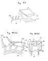
- FIG. 6 A modification of the present embodiment as illustrated in Fig. 6 will be described with reference to Fig. 14, wherein the vortex flow blower is provided with an impeller 1' of the double vane type.
- an annular flow passageway is formed also on the side of the cover 15 5 with the construction being similar to that previously described.
- a radial cooling ventilating passageway 34' is elongated to a location near the bearing 4a as shown in Fig. 15 to form a ventilating passageway for supplying cooling air to the bearing 14a.
- cooling fluid having passed the axial cooling ventilating passageway 36 also cools a portion near to the inner side bearing 14a and cools a bearing supporting portion which transmits heat by heat transfer from the annular flow passageway 3a, and accordingly, there is an effect of increasing the life of the bearing 14a.
- the present embodiment is similar in improvement in blower aerodynamic characteristic by cooling and also in facility in production of the casings 3 and 4. Since the ventilating passageway is formed in the electric motor casing, the possibility of admission of foreign substances can be prevented, with the construction being similar to that previously described.
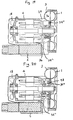
- FIG. 16 A modification to the embodiment of Fig. 15 is shown in Fig. 16, wherein a radial cooling ventilating passageway 34"is provided on the entire periphery of the bearing in order to restrict the bearing temperature so as to assure a long life.
- the present modification has, in addition to such structure wherein the supporting portion for the bearing 14a can be cooled as described above with reference to Fig. 15, a structure wherein a portion other than part of the bearing supporting portion is formed as the radial cooling ventilating passageway 34", and a long life is assured by an increase of the cooling area and restriction of heat transfer from the supporting portion to the bearing 14a.
- FIG. 19 Another embodiment of the present invention will be described with reference to Fig. 19, wherein air of the radial ventilating passageway 34" is discharged also from the electric motor housing 4 by way of a port 24 communicated with the radial ventilating passageway and is provided on an upper face of the electric motor casing 4 adjacent the blower casing 3.
- air flowing along the axial ventilating passageway flows toward the bearing 14a, and the cooling efficiency of the bearing 14a can be improved.
- a first modification to the present embodiment will be described with reference to Fig. 20, wherein a fan 48 is provided around a hub of the impeller 1 so as to perform compulsory blasting and agitation.
- a once-through fan, a radial fan or the like can be employed as the fan 48.
- an electric motor 30 is connected in an integral relationship as a driver in the embodiments described so far, the driver may have a different construction and rotation may be transmitted by way of a belt or the like from an electric motor installed separately. Additionally, blast air to the radial ventilating passageway 34 may be supplied from an air blower installed separately. With the above-described constructions, a vortex flow blower can be obtained which is small in size, superior in productivity and superior also in aerodynamic performance.
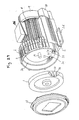
- a vortex flow blower has the casing 2 including the blower casing 3 serving as an impeller casing, the motor casing 4 and the silencer casing 5 constructed in an integrally connected condition as illustrated in Fig. 22.
- the impeller is fastened to the main shaft 14 with a small gap g left from the casing 2 and the electric motor 30 including the rotor 16 fitted on the main shaft 14 and the stator 17 fitted in the motor casing 4 are accommodated in the casing 2.
- the cover 15 which is formed from a thin plate is mounted in such a manner as to cover the impeller 1 and has a rectangular recessed shape at a central portion thereof and is securely mounted at an opening portion of the blower casing 3 remote from the electric motor 30.
- the fan 18 for cooling the electric motor fastened to the main shaft 14 is provided on the outer side of an end bracket 22, and the cooling fan cover 19 is secured to the end bracket 22 in such a manner as to cover the cooling fan 18.
- the annular flow passageway 3a is formed in the blower casing 3 in an opposing relationship to vanes 1 a of the impeller 1, and the silencer casing 5 in which a silencing material 7 is disposed is securely mounted at the inlet port 3b and the outlet port 3c provided for the annular passageway 3a.
- a silencer casing cover 20 in which such silencing material 7 is disposed as shown in Fig. 25 is mounted at an end face remote from the inlet port 3b and outlet port 3c.
- a flange 21 is provided at an end face of the silencer casing cover 20 so that a pipe may be connected to the same.
- the blower casing 3, motor casing 4 and silencer casing 5, formed in an integral relationship with each other, have a configuration which is determined taking parting of a die into consideration so that they may be produced by die-casting as shown in Fig. 23 and can be produced in mass. Additionally, for reduction of the number of operation steps in assembly, the silencer casing cover 20 is formed so that it can be readily assembled to the silencer casing 5.
- the casing 2 is formed as a unitary member by aluminum die-casting in the present embodiment. Consequently, the number of operation steps in assembly of the blower casing 3, motor casing 4 and silencer casing 5 can be reduced. Further, since boring, finishing and so forth of the blower casing 3 and motor casing 4 can be performed simultaneously, the number of arranging steps is reduced and the number of operation steps can be reduced. Further, since the positional relationship among the blower casing 3, motor casing 4 and silencer casing 5 can always be kept constant, the accuracy in assembly and working is improved, and uniformity of the quality and improvement of the reliability can be achieved.
- an end face of the silencer casing 5 remote from the blower casing 3 is formed in a displaced relationship by a distance b (b 0) such that it may be either flush with an end face of the motor housing 4 remote from the blower casing 3 or displaced slightly toward the blower casing 3. Consequently, when the silencer casing cover 20 is mounted onto the silencer casing 5, interference with the cooling fan cover 19 can be prevented, and the operability in assembly can be improved.
- the casing 2 has a rib 32 between the motor casing 4 and the silencer casing 5 as shown in Figs. 23 and 24. Since the electric motor 30 having the stator 17 and the rotor 16 built in the motor housing 4 has a great mass, it tends to be moved down by gravitational force.
- the main shaft 14 tends to be inclined and the gap g between the blower casing 3 and the impeller 1 tends to expand at the upper half and to reduce at the lower half, the motor casing 4 is supported by the rib 32 provided between the motor casing 4 and the silencer casing 5. Consequently, the gap g is stabilized, and an abutting phenomenon of the impeller 1 with the blower casing 3 can be prevented and the performance is stabilized.
- the rib 32 is provided on the side of the silencer casing 5 adjacent an inlet port 6 corresponding to the inlet port 3b of the blower casing, and compression heat of gas pressurized by the impeller 1 is not transmitted to the electric motor readily. Thus, a temperature increase of the electric motor 30 can be restricted.
- the rib 32 is provided such that the direction thereof coincides with the parting direction of a die when it is cast integrally by diecasting so that simplification of the die and shortening of a die-casting step can be attained.
- heat radiating fins 4a are provided on the motor housing 4, and heat radiating fins 3k are provided on the blower casing 3 continuously to the fins 4a.
- cooling air passageway 36 is provided in the form of a gap between the motor casing 4 and the silencer casing and further, the radial passageway 34 is provided in communication with the axial passageway gap 36 between the blower casing 3 and the silencer casing 5.
- the impeller 1 is rotated by the electric motor 30, and fluid taken in by way of the inlet port 6 passes through an inlet side ventilating passageway 8 (Fig. 24) of the silencer casing 5 in which the silencing material 7 is filled and a volume necessary to provide a sufficient silencing effect is assured, and then enters, past the inlet port 3b, the annular passageway 3a in which it is pressurized by the impeller 1.
- the pressurized fluid is discharged from the outlet port 3c and then passes through an outlet side ventilating passageway 9 (Fig. 24) of the silencer casing 5 in which such volume is assured similarly as in the inlet side ventilating passageway 8, whereupon noises are reduced, whereafter it is discharged from the outlet port 10 corresponding to the outlet port 3c of the blower casing.
- cooling fluid advances in the narrow gap 36 provided between the motor casing 4 and the silencer casing 5 such that it flows positively along a surface of the motor casing 4, and then it enters the radial passageway 34 provided between the blower casing 3 and the silencer casing 5 from an entrance portion 34a, whereafter it cools a lower portion of the blower casing 3 and is then discharged from an exit opening 34b in a bottom wall as shown in Fig. 27.
- a terminal box 86 is provided on an upper face of the motor housing 4, and by changing the orientation in which the terminal box 86 is mounted to change the orientation of a wire lead-in hole, a wire can be connected from an arbitrary direction.
- a capacitor 80 is required, and as an accommodating location for such capacitor 80, the fins of the motor housing 4 are partially made lower as shown in Fig. 24. Consequently, the capacitor 80 is prevented from being projected from a maximum diameter of the blower casing 3, thereby achieving reduction in size of the vortex flow blower.
- the vortex flow blower after completion of assembly has an outer configuration as shown in Figs. 1 and 2. Furthermore, in accordance with the present embodiment, the silencer casing 5 has at a bottom portion thereof a pair of rising portions 5b each of which rises from an inner side of a maximum width portion of the blower casing 3 and has a swollen or bulging portion 5c which is swollen to an outer periphery along an outer periphery of the motor casing 4 and extends continuously to the rising portion 5b. Due to the construction, transportation of the vortex flow blower is facilitated and the operability upon production can be improved.
- FIG. 29-33 there is shown another embodiment of the present invention wherein the vortex flow blower is utilized as a vortex flow type air pump.
- the annular groove 3a opposing to vanes 1 a of the impeller 1' is formed in the blower casing 3 as shown in Fig. 30 and the silencer casing 5, in which the silencing material 7 is disposed, is securely mounted at the inlet port 3b and the outlet port 3c provided at the opposite ends of a partition wall 3d which partitions part of a circumference of the annular groove 3a.
- the silencer casing cover 20 and flange 21 are provided on the silencer casing 5.
- reducing members 3e and 3f for individually reducing the sectional area of the annular groove 3a are provided at a portion of the annular groove 3a contiguous to the inlet port 3b and another portion contiguous to the outlet port 3c, respectively, as shown in Fig. 31.
- Each of the reducing members 3e and 3f is formed by projecting an inner face of the annular groove 3a in a direction toward the impeller 1 as shown in Fig. 32.
- the reducing members 3e and 3f are constructed such that they have portions which smoothly continue to the portion contiguous to the inlet port 3b and the portion contiguous to the outlet port 3c, respectively, and they further have portions which continue to an intermediate portion 3g of the annular groove 3a.
- the impeller 1 when the electric motor 30 is operated, the impeller 1 is rotated around the rotary shaft 14, and an internal fow is produced in the annular groove 3a and an impeller annular groove 1 by the plurality of vanes 1 a provided in the impeller annular groove 1 b. Consequently, air admitted from the inlet port 3b forms an internal flow which continues to the exit port 3c via the sectional area reducing member 3e on a partition wall 3d side of an end portion of a partition wall portion 3d, the intermediate portion 3g of the annular groove 3a and the sectional area reducing member 3f on a partition wall 3db side of an end portion of the partition wall portion 3d. It is to be noted that, in Fig. 29, the partition walls 3da and 3db at the end portions of the partition wall portion 3d are not shown.
- the amount of air can be increased. Further, since the flow passageway is gradually expanded from the sectional area reducing member toward the intermediate portion 3g of the annular groove 3a, the increased flow speed is decreased to achieve pressure restoration from a dynamic pressure to a static pressure, and a high air pressure can be attained.
- an effect that the amount of inlet air increases by 10 percent or so and another effect that the noise level is reduced by 3 dB or so by prevention of collision of an outlet flow by the outlet side annular groove reducing section is reduced by 50 percent.
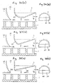
- a plate 40 is provided in an inclined relationship to a circumferential direction in the annular groove 3a.
- the plate 40 is formed flat on the side thereof opposing to the impeller 1 while it is formed such that the side thereof for contacting with the engaging groove 3a extends along a bottom face of the annular groove 3a.
- the plate 40 forms inlet side sectional area reducer and outlet side sectional area reducer, it is possible to form an annular groove reducing portion readily.
- FIGs. 36(a) and 36(b) show sectional area reducing member 42 having a flat portion at a top portion thereof which is connected smoothly linearly to the annular groove intermediate portion 3g.
- Figs. 37(a) and 37(b) show a modification wherein an apex of a sectional area reducing member 43 which rises accurately from the inlet port 3b and the annular groove intermediate portion 3g are connected smoothly linearly to each other.
- 38(a) and 38-(b) show a modification to the present embodiment wherein an apex of sectional area reducing member 44 which rises substantially vertically from the inlet port 3b and the annular groove intermediate portion 3g are coupled smoothly linearly to each other. Any of these constructions has an effect that a static pressure can be restored and the pressure characteristic is improved.
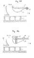
- FIG. 39(a) and 39(b) Another embodiment of the present invention will be described with reference to Figs. 39(a) and 39(b), wherein a sectional area reducing member 45 and the annular groove intermediate portion 3g are coupled smoothly to each other on the inlet side, the inclination on the inner periphery side is made smooth as compared with the inclination on the outer periphery side to improve the aerodynamic characteristic.
- FIG. 40 to 42 A further embodiment of the present invention will be described with reference to Figs. 40 to 42, wherein on the inlet side of the annular groove 3a, a sectional area reducing member 46 is provided and a guide plate 47 for dividing the inside of the annular groove 3a into a plurality of sections in a direction from the inner periphery side to the outer periphery side is provided in the same direction on the sectional area reducing member 46. Consequently, a disorder of an internal flow in a radial direction can be restricted and the aerodynamic characteristic can be improved.
- Figs. 41(a) and 41(b) show an example wherein a single guide plate 47 is provided whereas Figs. 42(a) and 42(b) show another example wherein two guide plates 47 are provided.
- FIGs. 43 and 44 show examples wherein a guide plate 50 is provided as sectional area reducing member in the annular groove 3a with Fig. 43 showing the guide plate 50 provided in spaced relationship from a bottom face of the annular groove 3a and Fig. 44 showing the guide plate 50 provided such that an end thereof is held in contact with a bottom face of the inlet port 3b or the outlet port 3c of the annular groove 3a.
- a guide plate 50 is provided as sectional area reducing member in the annular groove 3a with Fig. 43 showing the guide plate 50 provided in spaced relationship from a bottom face of the annular groove 3a and Fig. 44 showing the guide plate 50 provided such that an end thereof is held in contact with a bottom face of the inlet port 3b or the outlet port 3c of the annular groove 3a.
- Fig. 45 shows another embodiment of the present invention wherein the sectional area reducing member is constituted from a guide plate 51 which is a member separate from the blower casing 3.
- the guide plate 51 is formed in such a shape that it reduces the sectional area of the annular groove 3a and introduces a flow of air smoothly, and is securely mounted on a bottom face of the annular groove 3a by a screw 52.
- the secure mounting location is varied to allow adjustment of the position so that the aerodynamic characteristic can be optimized.
- the sectional area reducing member is constituted from a guide plate 53 as a member separate from the blower casing 3 and is supported for pivotal motion by a support member 54.
- a screw 55 serves for adjusting the amount of movement of the guide plate in a direction toward the impeller 1.
- the guide plate 53 is formed in such a shape that it reduces the sectional area of the annular groove 3a and introduces an air flow smoothly.
- the screw 55 By turning the screw 55, the amount of movement of the guide plate 53 in a direction toward or away from the impeller 1 is adjusted and the sectional area of the annular groove 3a is varied.
- the sectional area can be adjusted and the aerodynamic characteristic can be optimized. It is to be noted that, in the above-described embodiments, construction other than the sectional area reducing member is similar. Also, generally any of the sectional area reducing members may be applied to the outlet side to reduce noises.
- a vortex flow blower which includes an impeller 60 having radial vanes particularly on the outer periphery side thereof and a casing 70 is provided in such a manner as to surround the impeller 60 and having an annular groove 70a along an outer periphery of the impeller 60.
- the impeller 60 is provided such that the vanes 60a are fitted in the annular groove 70a.
- An inlet port 70b or an outlet port 70c is provided in a radial direction adjacent a partition wall 70d in the annular groove 70a, and a sectional area reducing member 72 is provided intermediately from the inlet port 70b or outlet port 70c to an annular groove intermediate portion 70g such that it is projected from a bottom face of the annular groove 70a.
- the sectional area reducer 72 is formed also at portions opposing the opposite side faces of the vanes 60a. The present embodiment can attain improvement in aerodynamic characteristic on the inlet side and reduction in noise level on the outlet side.
- the present invention may be applied to a vortex flow type liquid pump (Wesco pump).
- a vortex flow pump with which an increase in flow rate and pressure can be achieved and which has a superior characteristic.
- a vortex flow pump which is low in noise can be obtained.
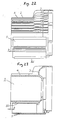
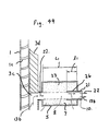
- Fig. 49 shows a partial side elevational sectional view of the inside of the silencer casing 5 having silencer material 7 disposed therein and positional at the outlet port 10 side of the vortex blower according to another embodiment of the present invention.
- the silencer casing 5 delimits an expansion chamber 23 having sound absorption material 7 therein so as to delimit a ventilation passageway 8 together with a pipe 26 partially inserted therein.
- Fig. 49 shows the pipe 26 mounted in an integral relationship with a side cover of the casing 5 to form the ventilating passageway.
- the length l 1 of the pipe 26 in the present embodiment is determined from two points of view as described below.
- the first point of view since the pipe inserted constitutes a part of the expansion chamber 23, the characteristic of reflected waves varies depending upon the dimension of l 1 . Accordingly, interference between reflected waves and incidence waves in the ventilating pipe is varied, and consequently, the silencing characteristic of the silencer is varied.
- the dimension of t i is determined so that the silencing characteristic of the silencer may be such that a required amount of silenced sounds may be obtained in a required frequency region.
- the second point of view is an influence upon an incidence area when sound waves of the ventilating passageway 8 are introduced in the sound absorption material 7 filled in the expansion chamber 23.
- the noise level at the exit of the silencer was measured varying the length,l 1 of the pipe 26 to various values in a condition wherein both of the sound absorption material 7 and the pipe 26 were inserted in the silencer casing 5.
- the noise level was reduced as compared with that where a pipe 26 was not inserted in the silencer, but where l 1 /L 1 was higher than 0.6, data was obtained indicating higher noise level than that when a pipe was not inserted.
- Fig. 50 shows a frequency characteristic of noises of the vortex flow blower considered as the sound pressure level (dB).
- the rotation sounds are at a frequency of 1,160 Hz.
- the operating condition of the blower is the case wherein the flow coefficient is 0.2 (near to the point of cut-off) at which the vortex blower is used most frequently.
- the curve (1) in the characteristic diagram indicates the characteristic when the silencer contains no sound absorption material and no insertion pipe (that is, the case wherein only a simple expansion type silencer is involved): the curve (2) indicates the characteristic when the sound absorption material 7 is present in the expansion chamber 23 but the insertion pipe 26 is not present: and the curve (3) indicates the characteristic where both the sound absorption material 7 and the insertion pipe 26 are present.
- the noise level in the case of the characteristic (1) is 83 dB: the noise level in the case of the characteristic (2) is 68 dB: and the noise level in the case of the characteristic (3) is 62 dB.
- the characteristic (1) is high in noise level SL, also the rotational sounds fr (1.25 kHz) are high at 79 dB and have a shrill tone.
- the difference between the characteristic (1) and the characteristic (2) arises from the silencing effect of the sound absorption material 7, and the sound quieting effect at a sound level is 15 dB and high.
- the difference between the characteristic (2) and the characteristic (3) indicates the silencing effect by the insertion of the pipe 26, and the difference in noise level is up to 5dB.
- the pipe 26 is effective for silencing or reducing noise level.
- FIG. 51 Another embodiment of the present invention is shown in Fig. 51, wherein the pipe 26 is mounted in the neighborhood of the impeller 1 in the inside of the silencer to form with the silencing material 7 the ventilating passageway 8.
- the silencing effect also of the insertion pipe 26 of Fig. 51 is substantially similar to the silencing effect of the case wherein the pipe of the case of Fig. 51 is located on the flange 21 side from the principle of utilization of interference between reflected waves from the expansion chamber 23 and incidence waves of the ventilating passageway 8.
- the silencing effect of 4 dB was obtained only with the insertion pipe as is shown in Fig. 50 and a noise characteristic similar to the characteristic (3) was able to be obtained.
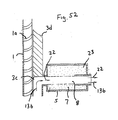
- Fig. 52 further embodiment of the present invention is shown in Fig. 52, wherein an insertion pipe 26' is formed in an integral relationship with the flange.
- the pipe 26 and the flange 21 can be readily formed as an insertion pipe 26' in the inside of the silencer 5 due to integral formation.
- the silencing effect of the insertion pipe of Fig. 52 is similar to that of Fig. 51, and a high silencing effect is obtained.
- FIG. 53 A still further embodiment of the present invention is shown in Fig. 53, wherein two pipes are inserted including a pipe 26a on the impeller 1 side and another pipe 26b on the flange side.
- the lengths of the pipes are represented by l 11 and l 12
- l 11 + l 12 2 is equal to the pipe length l1 1 of Fig. 49
- a silencing effect substantially close to the silencing effect of the embodiment shown in Fig. 49 was able to be obtained.
- a silencer in this instance has a configuration wherein a thin and short pipe (branch pipe) is erected substantially vertically uprightly with respect to the insertion pipe shown in Fig. 49 as shown in Figs. 54 and 55 which are views showing side elevational sectional views of the inside of the outlet port 10 side of the silencer.
- a branch pipe 27 extends from the pipe 26 with Fig. 55 being a sectional view taken along line XX' of Fig. 54 and showing an end part 28 of the branch pipe.
- Noises 22a produced by the vortex flow blower pass the ventilating passageway 8 in the silencer 5 and reach (22b) a joining location (position X 1 ) between the pipe 26 and the branch pipe 27.
- position X 1 a joining location between the pipe 26 and the branch pipe 27.
- part of the sound waves are introduced into the inside of the branch pipe 27 and then propagate in the branch pipe.
- the sound waves reflected by the branch pipe extreme end 28 are returned (22d) to the joining location Xi again.
- the sound waves 22d returned then and the sound waves 22b which have flowed newly in the ventilating passageway 8 and reach the Xi point interfere with each other so that the sound pressure level of the sound waves 22b is reduced considerably.
- the sound waves 22e which propagate at the outlet port 10 of the silencer are reduced in noise remarkably as compared with a construction wherein the branch pipe 27 is not present.
- Fig. 56 shows a frequency characteristic curves for noises of the vortex flow blower.
- the operating condition of the blower is the case wherein the flow coefficient is 0.2 (near to the point of cut-off) at which the vortex flow blower is used most frequently.
- the curves (1) and (3) in the characteristic diagram shown in Fig. 56 are the same as in Fig. 50, and the curve (1) indicates the characteristic where the silencer contains no sound absorption material while the curve (3) indicates the characteristic where the silencer contains the sound absorption material.
- the noise level in the case of the characteristic curve (1) is 83 dB: and the noise level in the case of the characteristic 3 is 62 dB.
- a curve (4) shows a noise characteristic of the case of Figs. 54 and 55, and the noise level is 58 dB and is lower by 4 dB as compared with the characteristic curve (3). Further, the sound pressure level of the frequency fr (1.25 kHz) of rotation is lower by 10 dB as compared with the characteristic curve (3). Additionally, the sound pressure level is generally flat over a wide frequency range and the tone is soft. In particular, the silencer of Figs. 54 and 55 not only decreases the noise level further by 4 dB as compared with that of Fig. 49 but also quiets the tone so as to be soft rather than shrill.
- Fig. 57 is a view showing a yet further embodiment of the present invention, wherein loop portions of sound waves of a frequency to be reduced are not located at a ventilating portion of the pipe 26, but rather at an intermediate position between the entrance 10a and the exit 10b of the silencer.
- mounting of the branch pipe 27 has such a form wherein it is mounted on the pipe of a perforated plate 25 screen for protecting a ventilating portion of the sound absorption material 7.
- the silencing action of the branch pipe in the case of Fig. 57 is similar to that in the case of Fig. 54.
- Fig. 58 is a view showing a yet further embodiment of the present invention, wherein the branch pipe 27 extends in the longitudinal direction and for accommodation in the inside of the silencer casing 5, a rear half portion of the branch pipe is bent like an inverted or reverse h-shape. Since propagation of sound waves in the inverse h-shaped branch pipe proceeds such that, similarly as in the case of the straight branch pipe of Fig. 54, sound waves are reflected by the branch pipe extreme end 28 and propagate toward an entrance portion of the branch pipe, a silencing effect similar to the silencing effect of the case of Fig. 54 can be obtained with the branch pipe of Fig. 58.
- Fig. 59 is a view showing a yet further embodiment of the present invention, wherein a position X 3 at which the branch pipe 27 is mounted, is external of the silencer casing 5 at the flange 21.
- Fig. 60 shows a case wherein a rear half portion of the branch pipe is bent into a reverse h-shape and the branch pipe rear half portion is disposed within the silencer casing 5 to increase the strength of the branch pipe in handling.
- the branch pipe is mounted perpendicularly with respect to the flange 21.
- a sound absorption material having a passageway therein is provided in a silencer of a vortex flow blower and a pipe is inserted over a suitable length in the passageway, there is an effect that the ventilating resistance can be restricted and direct projection sounds from the inlet and outlet ports of the vortex flow blower can be reduced remarkably. Further, since a branch pipe is provided, also a dominant sound pressure level can be reduced. As a result noises radiated from the inlet and outlet ports of the silencer of the vortex flow blower are reduced in noise level by 8 to 10 dB from those of a conventional construction. Further, since there is no dominant sound, the tone is soft, and there is an effect that the noise characteristic is improved remarkably.
- the blower has a casing 2 comprising a unitary assembly of a blower casing 3 as an impeller casing, a motor casing 4, and a silencer or muffler casing 5.
- the casing 2 houses the impeller 1 secured to the main shaft 14 and slightly spaced apart from the casing 2, and an electric motor 30 which comprises the rotor 16 fitted about the main shaft 14 and the stator 17 fitted in the motor housing 4.
- the blower casing 3 has an opening which is remote from the motor 30, and which is closed by the cover 15 formed from a thin plate, having a rectangular recess in its center, held by lugs on the blower casing 3, and covering the impeller 1.
- the cover 15 formed from a thin plate, having a rectangular recess in its center, held by lugs on the blower casing 3, and covering the impeller 1.
- On the opposite side of the motor 30 from the impeller 1 i.e., opposite the load side), there are provided outwardly of an end bracket 22, the fan 18 secured to the main shaft 14 for cooling the motor, and the cooling fan cover 19 secured to the end bracket 22 and covering the cooling fan 18.
- the blower casing 3 defines the annular passage 3a facing the vanes or blades 1 of the impeller 1 and connected to the intake port 3b and a discharge port 3c.
- the silencer casing 5 holds a noise deadening material 7 and is connected to the intake and discharge ports 3b and 3c.
- a silencer casing cover 20 holds the noise deadening material 7 and is connected to that end of the silencer casing 5 which is remote from the intake and discharge ports 3b and 3c, and respective flanges 21 are provided on the outer end of the cover 20.
- the silencer casing 5 is a casing having a base wall 5e having a width I which is smaller than the maximum width L of the blower casing 3.
- the silencer casing has sidewalls 5a each having an upstanding portion 5b rising from one of the opposite edges of the base wall 5g, and a bulging portion 5c contiguous with the upstanding portion 5b and curved outwardly along the outer periphery of the motor.
- gas is drawn into an intake port 6, flows through an intake flow path 9 delimited by the silencer casing 5, filled with the sound absorbing material 7, and having the necessary volume for exhibiting a satisfactorily high effect of absorbing sound, and through the intake port 3b into the annular passage 3a, and is compressed by the impeller 1.
- the compressed gas is discharged through the discharge port 3c, and flows through a discharge or ventilating flow path 8 delimited by the silencer casing 5 and the sound absorbing material 7 and having as large a volume as that of the intake flow path 9, whereby the noise produced by the gas is reduced, whereafter the gas is discharged through the discharge port 10.
- the silencer casing 5, as described, enables a noise reduction of 4 to 5 dB as compared with any counterpart known in the art.
- a width reduction of 20% is possible with a height reduction of 20%.
- a noise reduction of several more decibels can be achieved by the combination of the silencer casing 5 with a three-dimensional impeller as disclosed in Japanese Patent Application Laid-open No. 212920/1989 or 242232/1989.
- the bulging sidewall portions of the silencer casing 5 are provided with ribs 11, as shown in Figs. 62-64. They provide an increased frictional force as required for lifting the pump, and thereby facilitate the transportation and handling thereof.
- the ribs 11 extend in direction of the shaft 14 of the motor 30. In other words, they are so formed as to extend in the direction in which a die cast or otherwise molded assembly of the blower casing 3, motor casing 4, and silencer casing 5 is removed from the mold. This arrangement enables a simple mold construction and a shortened die casting process.
- the motor casing 4 is provided with heat radiating fins 4a.
- the motor housing 4 carries a terminal box 36 on its top.
- the silencer casing 5 has at its bottom mounting legs 5d projecting laterally from its upstanding sidewall portions 5b.
- the legs 5d can be so sized as to define between the outer edges thereof a distance which is equal to the maximum diameter of the blower casing, since the upstanding portions 5b are recessed inwardly from the bulging portions 5c to make room for the work of tightening bolts and nuts on the legs 5d.
- a reduction can, however, be achieved in the overall size of the pump, since the legs 5d and the lugs for the cover are so constructed as not to project beyond the maximum diameter L of the blower casing 3.
- FIG. 65 Another embodiment of the present invention is shown in Fig. 65, wherein grooves 12 are provided on the bulging portions 5c of the sidewalls 5a of the silencer casing 5 as the frictional arrangement for facilitating the manual transportation of the pump.
- FIG. 66 A further embodiment of the present invention is shown in Fig. 66, wherein a member 13 of a material having a high coefficient of friction, such as rubber is bonded to the bulging portion 5c of each sidewall 5a of the silencer casing 5 for facilitating the transportation of the pump.
- This member is preferably formed of silicone rubber, or like material capable of withstanding a high temperature.
- the frictional members 13 may have any of a variety of shapes. Their shape can be so selected as to fit the hands well, and thereby facilitate the transportation and installation of the pump.
- the present invention provides a vortex flow blower or centrifugal pump applicable not only to air type but also liquid type which is easy to transport, produces an outstandingly good result of noise deadening, and has both a small height and a small muffler casing width.
Landscapes
- Engineering & Computer Science (AREA)
- Mechanical Engineering (AREA)
- General Engineering & Computer Science (AREA)
- Physics & Mathematics (AREA)
- Thermal Sciences (AREA)
- Structures Of Non-Positive Displacement Pumps (AREA)
Applications Claiming Priority (10)
| Application Number | Priority Date | Filing Date | Title |
|---|---|---|---|
| JP2242323A JP2865835B2 (ja) | 1990-09-14 | 1990-09-14 | 渦流ブロワ |
| JP242323/90 | 1990-09-14 | ||
| JP276324/90 | 1990-10-17 | ||
| JP27632490A JPH04153597A (ja) | 1990-10-17 | 1990-10-17 | 渦流ブロワ |
| JP279015/90 | 1990-10-19 | ||
| JP2279013A JP2776976B2 (ja) | 1990-10-19 | 1990-10-19 | 渦流ポンプ |
| JP279014/90 | 1990-10-19 | ||
| JP279013/90 | 1990-10-19 | ||
| JP2279014A JP2865849B2 (ja) | 1990-10-19 | 1990-10-19 | 渦流ポンプ |
| JP27901590A JP2714245B2 (ja) | 1990-10-19 | 1990-10-19 | 渦流ポンプ |
Publications (3)
| Publication Number | Publication Date |
|---|---|
| EP0477650A2 true EP0477650A2 (de) | 1992-04-01 |
| EP0477650A3 EP0477650A3 (en) | 1992-07-15 |
| EP0477650B1 EP0477650B1 (de) | 1996-05-29 |
Family
ID=27530066
Family Applications (1)
| Application Number | Title | Priority Date | Filing Date |
|---|---|---|---|
| EP91115274A Expired - Lifetime EP0477650B1 (de) | 1990-09-14 | 1991-09-10 | Seitenkanalgebläse |
Country Status (3)
| Country | Link |
|---|---|
| EP (1) | EP0477650B1 (de) |
| KR (1) | KR100190424B1 (de) |
| DE (1) | DE69119854T2 (de) |
Cited By (5)
| Publication number | Priority date | Publication date | Assignee | Title |
|---|---|---|---|---|
| FR2708678A1 (fr) * | 1993-08-06 | 1995-02-10 | Bosch Gmbh Robert | Pompe périphérique notamment pour pomper du carburant d'un réservoir vers un moteur à combustion interne d'un véhicule automobile. |
| WO2008125630A1 (de) * | 2007-04-13 | 2008-10-23 | Gebr. Becker Gmbh | Seitenkanalverdichter |
| EP2233749A1 (de) * | 2007-12-21 | 2010-09-29 | Yonehara Giken Co., Ltd. | Zentrifugaldruckpumpe |
| WO2019201448A1 (de) * | 2018-04-20 | 2019-10-24 | Siemens Aktiengesellschaft | Funktionseinheit eines verdichtersystems |
| WO2023184655A1 (zh) * | 2022-03-28 | 2023-10-05 | 林胜利 | 一种可调压式漩涡风机 |
Families Citing this family (5)
| Publication number | Priority date | Publication date | Assignee | Title |
|---|---|---|---|---|
| KR101377057B1 (ko) | 2012-08-02 | 2014-03-24 | (주) 에이스터보 | 터보 블로워장치 |
| DE102012023347B3 (de) * | 2012-11-29 | 2014-01-30 | Tni Medical Ag | Kleiner, geräuscharmer Seitenkanalverdichter, insbesondere für Geräte in der Beatmungstherapie |
| KR101911782B1 (ko) * | 2013-01-25 | 2018-10-26 | 한온시스템 주식회사 | 연료전지 차량용 공기 블로워 |
| DE102016103525A1 (de) * | 2016-02-29 | 2017-08-31 | Pierburg Gmbh | Gebläse für einen Verbrennungsmotor |
| DE102022210555A1 (de) | 2022-10-06 | 2024-04-11 | Ziehl-Abegg Se | Ventilator und Kühlstruktur für einen Ventilator |
Citations (5)
| Publication number | Priority date | Publication date | Assignee | Title |
|---|---|---|---|---|
| DE2021159A1 (de) * | 1969-05-02 | 1971-02-11 | Etri Sa | Mit einem Schalldaempfer versehene rotierende Pumpe fuer gasfoermige Stroemungsmittel |
| DE2001395A1 (de) * | 1970-01-14 | 1971-07-22 | Werner Rietschle Maschinen U A | Seitenkanalgeblaese |
| FR2384975A1 (fr) * | 1977-03-21 | 1978-10-20 | Siemens Ag | Compresseur a canal lateral |
| US4483656A (en) * | 1981-12-18 | 1984-11-20 | Hitachi, Ltd. | Vortex blower |
| JPS6483882A (en) * | 1987-09-25 | 1989-03-29 | Fuji Electric Co Ltd | Ring blower |
-
1991
- 1991-09-10 DE DE69119854T patent/DE69119854T2/de not_active Expired - Lifetime
- 1991-09-10 EP EP91115274A patent/EP0477650B1/de not_active Expired - Lifetime
- 1991-09-14 KR KR1019910016039A patent/KR100190424B1/ko not_active IP Right Cessation
Patent Citations (5)
| Publication number | Priority date | Publication date | Assignee | Title |
|---|---|---|---|---|
| DE2021159A1 (de) * | 1969-05-02 | 1971-02-11 | Etri Sa | Mit einem Schalldaempfer versehene rotierende Pumpe fuer gasfoermige Stroemungsmittel |
| DE2001395A1 (de) * | 1970-01-14 | 1971-07-22 | Werner Rietschle Maschinen U A | Seitenkanalgeblaese |
| FR2384975A1 (fr) * | 1977-03-21 | 1978-10-20 | Siemens Ag | Compresseur a canal lateral |
| US4483656A (en) * | 1981-12-18 | 1984-11-20 | Hitachi, Ltd. | Vortex blower |
| JPS6483882A (en) * | 1987-09-25 | 1989-03-29 | Fuji Electric Co Ltd | Ring blower |
Non-Patent Citations (1)
| Title |
|---|
| PATENT ABSTRACTS OF JAPAN, vol. 43, no. 289 (M-845)(3637), 5th July 1989; & JP-A-1 83 882 (FUJI ELECTRIC) 29-03-1989 * |
Cited By (7)
| Publication number | Priority date | Publication date | Assignee | Title |
|---|---|---|---|---|
| FR2708678A1 (fr) * | 1993-08-06 | 1995-02-10 | Bosch Gmbh Robert | Pompe périphérique notamment pour pomper du carburant d'un réservoir vers un moteur à combustion interne d'un véhicule automobile. |
| WO2008125630A1 (de) * | 2007-04-13 | 2008-10-23 | Gebr. Becker Gmbh | Seitenkanalverdichter |
| EP2166232A1 (de) | 2007-04-13 | 2010-03-24 | Gebr. Becker GmbH | Seitenkanalverdichter |
| EP2233749A1 (de) * | 2007-12-21 | 2010-09-29 | Yonehara Giken Co., Ltd. | Zentrifugaldruckpumpe |
| EP2233749A4 (de) * | 2007-12-21 | 2012-12-19 | Yonehara Giken Co Ltd | Zentrifugaldruckpumpe |
| WO2019201448A1 (de) * | 2018-04-20 | 2019-10-24 | Siemens Aktiengesellschaft | Funktionseinheit eines verdichtersystems |
| WO2023184655A1 (zh) * | 2022-03-28 | 2023-10-05 | 林胜利 | 一种可调压式漩涡风机 |
Also Published As
| Publication number | Publication date |
|---|---|
| DE69119854D1 (de) | 1996-07-04 |
| DE69119854T2 (de) | 1996-10-10 |
| EP0477650B1 (de) | 1996-05-29 |
| KR100190424B1 (ko) | 1999-06-01 |
| EP0477650A3 (en) | 1992-07-15 |
| KR920006657A (ko) | 1992-04-27 |
Similar Documents
| Publication | Publication Date | Title |
|---|---|---|
| KR100400153B1 (ko) | 원심 멀티블레이드 송풍기 | |
| EP0732511B1 (de) | Lärmdämpfungsgerät eines Lüfters | |
| US5749702A (en) | Fan for air handling system | |
| EP0477650A2 (de) | Seitenkanalgebläse | |
| JPH11105552A (ja) | 自動2輪車用ラジエタ冷却装置 | |
| CA1117086A (en) | Vane axial fan assembly | |
| JP2008138660A (ja) | 遠心送風機 | |
| US6971846B2 (en) | Centrifugal blower | |
| US3688867A (en) | Acoustically improved blower package | |
| JPH06281194A (ja) | 送風装置 | |
| CN115182899A (zh) | 蜗壳组件、风机和电器设备 | |
| JP3264553B2 (ja) | 送風装置 | |
| JP5151631B2 (ja) | 遠心送風機 | |
| JPH07127961A (ja) | 冷凍冷蔵庫 | |
| JPH07253267A (ja) | 冷凍冷蔵庫の通風構造 | |
| KR101802195B1 (ko) | 소음저감형 선박용 공조장치 | |
| CN111852907A (zh) | 鼓风机和鼓风机用箱体 | |
| JP3854679B2 (ja) | ブロワの消音装置 | |
| JPH07247989A (ja) | ターボブロワ | |
| JPH0874785A (ja) | ターボブロワ | |
| JPH094592A (ja) | ターボブロワ | |
| CN211432460U (zh) | 一种降噪效果好的食品加工机 | |
| CN215292652U (zh) | 静音型柴油发电机的导风散热机构 | |
| JPH09324977A (ja) | 冷蔵庫 | |
| JPH029073Y2 (de) |
Legal Events
| Date | Code | Title | Description |
|---|---|---|---|
| PUAI | Public reference made under article 153(3) epc to a published international application that has entered the european phase |
Free format text: ORIGINAL CODE: 0009012 |
|
| AK | Designated contracting states |
Kind code of ref document: A2 Designated state(s): DE FR GB IT |
|
| PUAL | Search report despatched |
Free format text: ORIGINAL CODE: 0009013 |
|
| AK | Designated contracting states |
Kind code of ref document: A3 Designated state(s): DE FR GB IT |
|
| 17P | Request for examination filed |
Effective date: 19920619 |
|
| 17Q | First examination report despatched |
Effective date: 19930908 |
|
| GRAH | Despatch of communication of intention to grant a patent |
Free format text: ORIGINAL CODE: EPIDOS IGRA |
|
| GRAA | (expected) grant |
Free format text: ORIGINAL CODE: 0009210 |
|
| AK | Designated contracting states |
Kind code of ref document: B1 Designated state(s): DE FR GB IT |
|
| REF | Corresponds to: |
Ref document number: 69119854 Country of ref document: DE Date of ref document: 19960704 |
|
| ET | Fr: translation filed | ||
| ITF | It: translation for a ep patent filed |
Owner name: MODIANO & ASSOCIATI S.R.L. |
|
| PLBE | No opposition filed within time limit |
Free format text: ORIGINAL CODE: 0009261 |
|
| STAA | Information on the status of an ep patent application or granted ep patent |
Free format text: STATUS: NO OPPOSITION FILED WITHIN TIME LIMIT |
|
| 26N | No opposition filed | ||
| REG | Reference to a national code |
Ref country code: GB Ref legal event code: IF02 |
|
| PGFP | Annual fee paid to national office [announced via postgrant information from national office to epo] |
Ref country code: FR Payment date: 20090820 Year of fee payment: 19 |
|
| PGFP | Annual fee paid to national office [announced via postgrant information from national office to epo] |
Ref country code: GB Payment date: 20090824 Year of fee payment: 19 |
|
| PGFP | Annual fee paid to national office [announced via postgrant information from national office to epo] |
Ref country code: DE Payment date: 20090824 Year of fee payment: 19 |
|
| PGFP | Annual fee paid to national office [announced via postgrant information from national office to epo] |
Ref country code: IT Payment date: 20090721 Year of fee payment: 19 |
|
| GBPC | Gb: european patent ceased through non-payment of renewal fee |
Effective date: 20100910 |
|
| PG25 | Lapsed in a contracting state [announced via postgrant information from national office to epo] |
Ref country code: IT Free format text: LAPSE BECAUSE OF NON-PAYMENT OF DUE FEES Effective date: 20100910 |
|
| REG | Reference to a national code |
Ref country code: FR Ref legal event code: ST Effective date: 20110531 |
|
| REG | Reference to a national code |
Ref country code: DE Ref legal event code: R119 Ref document number: 69119854 Country of ref document: DE Effective date: 20110401 |
|
| PG25 | Lapsed in a contracting state [announced via postgrant information from national office to epo] |
Ref country code: FR Free format text: LAPSE BECAUSE OF NON-PAYMENT OF DUE FEES Effective date: 20100930 Ref country code: DE Free format text: LAPSE BECAUSE OF NON-PAYMENT OF DUE FEES Effective date: 20110401 |
|
| PG25 | Lapsed in a contracting state [announced via postgrant information from national office to epo] |
Ref country code: GB Free format text: LAPSE BECAUSE OF NON-PAYMENT OF DUE FEES Effective date: 20100910 |