EP0471997B1 - Dispositif à clavette pour le raccordement de barres, plus spécialement de barres d'échafaudage - Google Patents
Dispositif à clavette pour le raccordement de barres, plus spécialement de barres d'échafaudage Download PDFInfo
- Publication number
- EP0471997B1 EP0471997B1 EP91112427A EP91112427A EP0471997B1 EP 0471997 B1 EP0471997 B1 EP 0471997B1 EP 91112427 A EP91112427 A EP 91112427A EP 91112427 A EP91112427 A EP 91112427A EP 0471997 B1 EP0471997 B1 EP 0471997B1
- Authority
- EP
- European Patent Office
- Prior art keywords
- wedge
- clamping part
- box
- web
- arrangement according
- Prior art date
- Legal status (The legal status is an assumption and is not a legal conclusion. Google has not performed a legal analysis and makes no representation as to the accuracy of the status listed.)
- Expired - Lifetime
Links
Images
Classifications
-
- E—FIXED CONSTRUCTIONS
- E04—BUILDING
- E04G—SCAFFOLDING; FORMS; SHUTTERING; BUILDING IMPLEMENTS OR AIDS, OR THEIR USE; HANDLING BUILDING MATERIALS ON THE SITE; REPAIRING, BREAKING-UP OR OTHER WORK ON EXISTING BUILDINGS
- E04G7/00—Connections between parts of the scaffold
- E04G7/30—Scaffolding bars or members with non-detachably fixed coupling elements
- E04G7/302—Scaffolding bars or members with non-detachably fixed coupling elements for connecting crossing or intersecting bars or members
- E04G7/306—Scaffolding bars or members with non-detachably fixed coupling elements for connecting crossing or intersecting bars or members the added coupling elements are fixed at several bars or members to connect
- E04G7/307—Scaffolding bars or members with non-detachably fixed coupling elements for connecting crossing or intersecting bars or members the added coupling elements are fixed at several bars or members to connect with tying means for connecting the bars or members
Definitions
- the invention relates to a wedge device according to the preamble of claim 1.
- a wedge device of this type is known for example from DE-A-27 57 189.
- it is used to attach the railing rods to the tubular stands and thus to hold the entire scaffolding together.
- the web of the wedge boxes is inclined by the wedge angle in relation to the longitudinal direction of the tube stand.
- the wedge forms the one leg of a flat U-shaped clamping part, the other so-called holding leg has a longitudinal slot parallel to the inner wedge surface.
- This holding leg extends outside of the Keilrithschen and is captively held on the wedge box by means of a transverse pin passing through the longitudinal slot.
- the clamping part is knocked out by means of an outwardly projecting nose and then rotated by almost 180 ° so that it hangs down on the cross pin.
- the invention has for its object to propose a wedge device that is corrosion resistant, easy to manufacture and easy to use.
- This object is achieved based on a generic wedge device according to the invention in that the web of the wedge box is caught in the slot between the legs of the clamping part. Although the slot is open, the ends of the wedge and the holding leg are so close to one another that the remaining opening is smaller than the cross-sectional width of the web. This means that a cross pin for holding the clamping part can be completely eliminated. If, for other reasons - see below - a cross pin is used, this can already be used in the manufacture of the wedge boxes before welding and galvanizing.
- a stop nose on the inside of at least one leg of the clamping part in the region of the slot opening, so that the clamping part, when it is pulled up quickly, abuts the lower edge of the wedge box and does not become jammed. If the slot opening is provided with bevels and its clear width is dimensioned so that the web of the wedge box passes through due to the elastic expansion of the clamping part, then this can easily be captively attached with a hammer blow to the wedge box.
- a significant simplification when working with the wedge device results in a further development of the invention in that the possibility is created to hold the clamping part in a so-called waiting position, in which the wedge is released but is only rotated by a small angle with respect to its clamping position.
- This is achieved in that the inner wedge surface facing the holding leg toward the slot opening is followed by a surface that is substantially less or oppositely inclined, in particular parallel, with respect to the outer and longer wedge surface.
- a shoulder is expediently provided between the two differently inclined inner wedge surfaces, and a hook-in nose can also be formed on this shoulder. The latter lies over the upper edge of the web of the wedge box.
- the wedge box on the web then have a narrower guide section which is matched to the thickness of the clamping part.
- the outer wedge surface can also be widened in a T-shape, for example by welding a flat profile along the section to be widened.
- a cross-sectionally T-shaped clamping part is preferably made of malleable cast iron.
- Flat clamping parts are expediently punched out of flat material.
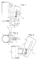
- Figures 1 to 3 show the pipe stand 1 of a scaffold frame to which a wedge box 2 is welded.
- the wedge box 2 is made of band iron and has a web 3 and two legs 4, which are chamfered in a mirror image stepwise, so that the wedge box receives a wider fastening section and a narrower guide section, the latter ending with the web 3.
- the legs 4 are penetrated by a cross pin 5 in the region of the guide section near the lower edge and the web.
- the tab 7 is inserted into the wedge box 2 from above, so that it lies tangentially on the pipe stand 1 and is pressed by the wedge 8 of a clamping part 9, as shown in FIGS. 1 and 2.
- the flat clamping part 9 which is preferably produced by stamping, is essentially U-shaped.
- One leg is formed by the wedge 8 and a subsequent strip-shaped section 10.
- the other leg is a holding leg 11 located outside the wedge box.
- the cross section of the web 3 and the transverse pin 5, which are to be considered here as a related cross-sectional configuration can be moved freely within the slot 12, but do not leave it. Rather, they would abut stop lugs 13 and 14, which are formed on the inside of the holding leg 11 or the section 10 and form the slot opening 15 between them. From the slot opening 15 to the lower edge of the clamping part 9, the slot widens over the bevels 16.
- the outer wedge surface 17 extends beyond the actual wedge 8 to the end of section 10.
- the inner wedge surface 18 is shorter. It continues over a shoulder through the inner surface 19 of the section 10, the latter running parallel to the outer wedge surface 17.
- a hook-in nose 20 is formed on the shoulder.
- the inner wedge surface 18 rests on the transverse pin 5 and on the upper edge 21 of the web 3. This results in the required inclined support, although the web 3 itself runs parallel to the longitudinal axis of the pipe stand 1.
- To release the clamping part 9 receives a stroke on its lower end. It can then easily be brought into the waiting position according to FIG. 3, in which the hook-in nose 20 engages over the upper edge of the web 3 and the holding leg 11 is supported on the lower outer edge of the web. In this position, the clamping part is rotated only by a small angle with respect to the clamping position according to FIG. 1.
- the tabs 7 of the cross tubes can be removed or hung in freely. You then only need to lift the clamping part 9 a little, after which the wedge 8 automatically falls into its clamping position and only needs to be tapped a little.
- the first insertion of the clamping part 9 into the wedge box is very simple.
- the web 3 is inserted into the slot 12 until the run-in slope 16 bears on the cross pin 5 at the section 10. If you knock on the clamping part 9 from above, the legs spread a little elastically, so that the nose 14 passes the cross pin 5. After that, pulling out without force is no longer possible.
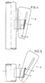
- FIGS. 4 and 5 show a variant of the described wedge device in that the wedge box 22 has a web 23 which is inclined by the wedge angle with respect to the axis of the tube stand 1. Accordingly, there is a simpler, elongated shape of the slot 24 in the wedge area of this clamping part 25. In the area of the slot opening there is only one stop lug 26.
- the function of the clamping part 25 is the same as in the previously described example, except that the inner wedge surface bears against the web 23 over its entire length.
Landscapes
- Engineering & Computer Science (AREA)
- Architecture (AREA)
- Mechanical Engineering (AREA)
- Civil Engineering (AREA)
- Structural Engineering (AREA)
- Clamps And Clips (AREA)
- Mutual Connection Of Rods And Tubes (AREA)
- Nonmetallic Welding Materials (AREA)
- Adornments (AREA)
Claims (9)
- Dispositif à clavette pour relier des parties de barre, le cas échéant des parties de barre en forme de tubes, en particulier des parties d'un échafaudage, comportant un support de clavette (2), pour l'essentiel en forme de U, qui est fixé par ses branches (4) à une partie de barre (1), et une clavette (8) maintenue, de façon à ne pas pouvoir être perdue, sur le support de clavette, clavette qui agit, en position de serrage, dans le support de clavette et qui prend appui avec ses surfaces de clavette, d'une part, contre la face interne du dos (3,23,34) du support de clavette, et d'autre part, contre une autre partie de barre (6) entourée du support de clavette ou contre une languette (7) d'une autre partie de barre, la clavette (8) formant l'une des branches d'un élément de serrage (9,25,35) en forme de U, dont l'autre branche, la branche de maintien (11), se trouve à l'extérieur du support de clavette (2),
caractérisé en ce que le dos (3,23,34) du support de clavette est prisonnier dans la fente (12,24) entre les branches de l'élément de serrage (9,25,35), le dos (3,23,34) du support de clavette (2), par suite d'un élargissement élastique des branches (8,11) de l'élément de serrage, traversant celui-ci, lorsque l'élément de serrage est enfoncé, de sorte qu'un enlèvement de l'élément de serrage (9,25,35) n'est plus possible sans force. - Dispositif à clavette selon la revendication 1,
caractérisé en ce que, dans la zone de l'ouverture de fente (15), une came de butée (13,14) est prévue, à l'intérieur, sur au moins une branche de l'élément de serrage (9). - Dispositif à clavette selon la revendication 1,
caractérisé en ce que l'ouverture de fente (15) est munie de biseaux d'entrée (16) et son diamètre interne est dimensionné de sorte que le dos (3) du support de clavette (2), par suite d'un élargissement élastique de l'élément de serrage (9), traverse celui-ci, lorsque l'élément de serrage est enfoncé. - Dispositif à clavette selon l'une des revendications précédentes,
caractérisé en ce qu'à la surface de clavette interne (18) en regard de la branche de maintien (11), vers l'ouverture de fente (15), est raccordée une surface (19), en particulier parallèle, essentiellement moins inclinée ou d'inclinaison opposée, par rapport à la surface de clavette (17) externe et plus longue. - Dispositif à clavette selon la revendication 4,
caractérisé en ce qu'un épaulement est prévu entre les deux surfaces de clavette internes (18 et 19) différemment inclinées. - Dispositif à clavette selon la revendication 5,
caractérisé en ce qu'une saillie d'accrochage (20) est formée sur l'épaulement. - Dispositif à clavette selon la revendication 1,
caractérisé en ce que le support de clavette (2) présente un segment de guidage plus mince, adapté à l'épaisseur de l'élément de serrage (9) et raccordé au dos (3). - Dispositif à clavette selon la revendication 1,
caractérisé en ce qu'une cheville transversale (5) traverse les branches (4) du support de clavette (2) de sorte que la surface de clavette interne (18) repose, simultanément, contre la cheville transversale (5) et contre le bord supérieur (21) du dos. - Dispositif à clavette selon la revendication 1,
caractérisé en ce que la surface de clavette externe est élargie en forme de T (36).
Priority Applications (1)
| Application Number | Priority Date | Filing Date | Title |
|---|---|---|---|
| AT91112427T ATE101421T1 (de) | 1990-08-23 | 1991-07-24 | Keilvorrichtung zum verbinden von stangenteilen, insbesondere eines baugeruests. |
Applications Claiming Priority (2)
| Application Number | Priority Date | Filing Date | Title |
|---|---|---|---|
| DE4026633 | 1990-08-23 | ||
| DE4026633A DE4026633A1 (de) | 1990-08-23 | 1990-08-23 | Keilvorrichtung zum verbinden von stangenteilen, insbesondere eines baugeruests |
Publications (2)
| Publication Number | Publication Date |
|---|---|
| EP0471997A1 EP0471997A1 (fr) | 1992-02-26 |
| EP0471997B1 true EP0471997B1 (fr) | 1994-02-09 |
Family
ID=6412732
Family Applications (1)
| Application Number | Title | Priority Date | Filing Date |
|---|---|---|---|
| EP91112427A Expired - Lifetime EP0471997B1 (fr) | 1990-08-23 | 1991-07-24 | Dispositif à clavette pour le raccordement de barres, plus spécialement de barres d'échafaudage |
Country Status (6)
| Country | Link |
|---|---|
| EP (1) | EP0471997B1 (fr) |
| AT (1) | ATE101421T1 (fr) |
| CZ (1) | CZ281168B6 (fr) |
| DE (2) | DE4026633A1 (fr) |
| HU (1) | HU210275B (fr) |
| SK (1) | SK259891A3 (fr) |
Families Citing this family (3)
| Publication number | Priority date | Publication date | Assignee | Title |
|---|---|---|---|---|
| DE19513436C1 (de) * | 1995-04-08 | 1996-11-07 | Karl Heinz Rinke | Haltevorrichtung für Streben eines Gerüsts |
| DE10241870A1 (de) * | 2002-09-09 | 2004-03-11 | Plettac Ag | Vorrichtung zur Verbindung von Baugerüstelementen |
| DE202004003626U1 (de) * | 2004-03-09 | 2004-05-19 | WAK - Gerüstvermietung GmbH | Baugerüstelement |
Family Cites Families (7)
| Publication number | Priority date | Publication date | Assignee | Title |
|---|---|---|---|---|
| GB1278596A (en) * | 1968-06-25 | 1972-06-21 | Kwikform Ltd | Improvements in or relating to builders scaffolding |
| US3807884A (en) * | 1971-11-08 | 1974-04-30 | Symons Corp | Releasable metal scaffolding connector |
| DE2757189C2 (de) * | 1977-12-22 | 1983-07-28 | Eberhard 7129 Güglingen Layher | Gerüst mit Rohrständern und Doppelgeländern |
| FR2496741A3 (fr) * | 1980-12-18 | 1982-06-25 | Entrepose | Echafaudage tubulaire et ses moyens d'assemblage |
| DE8706723U1 (de) * | 1987-05-11 | 1987-06-19 | MJ-Gerüst GmbH, 5970 Plettenberg | Vorrichtung zum Einhängen und Festklemmen von Rückengeländern an begehbaren Gerüsten, insbesondere Baugerüsten |
| DE3801354A1 (de) * | 1987-05-11 | 1988-12-01 | Mj Geruest Gmbh | Vorrichtung zum einhaengen und festklemmen von rueckengelaendern an begehbaren geruesten, insbesondere baugeruesten |
| DE3832480A1 (de) * | 1988-09-24 | 1990-03-29 | Geb Layher Langer | Halterung fuer gelaender an geruesten |
-
1990
- 1990-08-23 DE DE4026633A patent/DE4026633A1/de not_active Withdrawn
-
1991
- 1991-07-24 DE DE91112427T patent/DE59101006D1/de not_active Expired - Fee Related
- 1991-07-24 AT AT91112427T patent/ATE101421T1/de not_active IP Right Cessation
- 1991-07-24 EP EP91112427A patent/EP0471997B1/fr not_active Expired - Lifetime
- 1991-08-16 HU HU912727A patent/HU210275B/hu not_active IP Right Cessation
- 1991-08-22 CZ CS912598A patent/CZ281168B6/cs unknown
- 1991-08-22 SK SK2598-91A patent/SK259891A3/sk unknown
Also Published As
| Publication number | Publication date |
|---|---|
| HU210275B (en) | 1995-03-28 |
| SK278735B6 (sk) | 1998-02-04 |
| ATE101421T1 (de) | 1994-02-15 |
| CZ281168B6 (cs) | 1996-07-17 |
| HUT60354A (en) | 1992-08-28 |
| CZ259891A3 (en) | 1993-05-12 |
| SK259891A3 (en) | 1998-02-04 |
| DE4026633A1 (de) | 1992-02-27 |
| DE59101006D1 (de) | 1994-03-24 |
| HU912727D0 (en) | 1992-01-28 |
| EP0471997A1 (fr) | 1992-02-26 |
Similar Documents
| Publication | Publication Date | Title |
|---|---|---|
| EP2685111B1 (fr) | Dispositif de serrage de connexion amovibles de deux pièces profilées | |
| DE2704398C3 (de) | Aus Ständern und Riegeln zusammensetzbares Gerüst | |
| EP0876541A1 (fr) | Noeud d'echafaudage | |
| DE3513384A1 (de) | Profilsystem zum bau von montageeinrichtungen, stuetzkonstruktionen und transportbaendern | |
| DE2916826C2 (fr) | ||
| DE102006015348A1 (de) | Deckenschalungssystem | |
| DE2757189C2 (de) | Gerüst mit Rohrständern und Doppelgeländern | |
| DE1684219C3 (de) | Vorrichtung zum Verbinden von Gerüstteilen | |
| EP0471997B1 (fr) | Dispositif à clavette pour le raccordement de barres, plus spécialement de barres d'échafaudage | |
| EP0512428B1 (fr) | Plate-forme de travail pour murs ou coffrages | |
| EP0519316B1 (fr) | Rayonnage à consoles | |
| EP0649951B1 (fr) | Coffrage pour béton | |
| EP0268197B1 (fr) | Echafaudage, plus spécialement échafaudage pour le bâtiment | |
| DE3513553A1 (de) | Zerlegbares regal, insbesondere palettenregal | |
| DE10010229C1 (de) | Haltevorrichtung zum Befestigen von wenigstens einem Geländerrohr an einem Rohrständer eines Gerüstes | |
| EP0331796A1 (fr) | Dispositif renforcé de suspension pour câbles | |
| EP4562256B1 (fr) | Agencement de composants d'échafaudage pour un échafaudage | |
| DE4405977C2 (de) | Konsole für die Abstützung einer Gerüstbühne | |
| DE3814912C2 (fr) | ||
| EP3354818A1 (fr) | Dispositif de compensation en longueur pour échafaudages | |
| DE3815338A1 (de) | Im bauwesen zu verwendende geraetschaften, insbesondere gesimsschalungshalter oder zwinge | |
| DE4401987C1 (de) | Geländer, insbesondere für Parkplattformen | |
| DE4013093A1 (de) | Vorrichtung zum verbinden von profiltraegern | |
| DE1554373A1 (de) | Lagergestell | |
| DE8423109U1 (de) | Verbindungsmittel für Schalungstafeln |
Legal Events
| Date | Code | Title | Description |
|---|---|---|---|
| PUAI | Public reference made under article 153(3) epc to a published international application that has entered the european phase |
Free format text: ORIGINAL CODE: 0009012 |
|
| AK | Designated contracting states |
Kind code of ref document: A1 Designated state(s): AT BE CH DE FR IT LI LU |
|
| 17P | Request for examination filed |
Effective date: 19920418 |
|
| 17Q | First examination report despatched |
Effective date: 19930618 |
|
| GRAA | (expected) grant |
Free format text: ORIGINAL CODE: 0009210 |
|
| AK | Designated contracting states |
Kind code of ref document: B1 Designated state(s): AT BE CH DE FR IT LI LU |
|
| REF | Corresponds to: |
Ref document number: 101421 Country of ref document: AT Date of ref document: 19940215 Kind code of ref document: T |
|
| REF | Corresponds to: |
Ref document number: 59101006 Country of ref document: DE Date of ref document: 19940324 |
|
| ET | Fr: translation filed | ||
| ITF | It: translation for a ep patent filed | ||
| EPTA | Lu: last paid annual fee | ||
| PLBE | No opposition filed within time limit |
Free format text: ORIGINAL CODE: 0009261 |
|
| STAA | Information on the status of an ep patent application or granted ep patent |
Free format text: STATUS: NO OPPOSITION FILED WITHIN TIME LIMIT |
|
| 26N | No opposition filed | ||
| PGFP | Annual fee paid to national office [announced via postgrant information from national office to epo] |
Ref country code: LU Payment date: 19960701 Year of fee payment: 6 |
|
| PGFP | Annual fee paid to national office [announced via postgrant information from national office to epo] |
Ref country code: AT Payment date: 19960712 Year of fee payment: 6 |
|
| PGFP | Annual fee paid to national office [announced via postgrant information from national office to epo] |
Ref country code: BE Payment date: 19960725 Year of fee payment: 6 |
|
| PGFP | Annual fee paid to national office [announced via postgrant information from national office to epo] |
Ref country code: CH Payment date: 19960729 Year of fee payment: 6 |
|
| PGFP | Annual fee paid to national office [announced via postgrant information from national office to epo] |
Ref country code: FR Payment date: 19960730 Year of fee payment: 6 |
|
| PG25 | Lapsed in a contracting state [announced via postgrant information from national office to epo] |
Ref country code: LU Free format text: LAPSE BECAUSE OF NON-PAYMENT OF DUE FEES Effective date: 19970724 Ref country code: AT Free format text: LAPSE BECAUSE OF NON-PAYMENT OF DUE FEES Effective date: 19970724 |
|
| PG25 | Lapsed in a contracting state [announced via postgrant information from national office to epo] |
Ref country code: LI Free format text: LAPSE BECAUSE OF NON-PAYMENT OF DUE FEES Effective date: 19970731 Ref country code: CH Free format text: LAPSE BECAUSE OF NON-PAYMENT OF DUE FEES Effective date: 19970731 Ref country code: BE Free format text: LAPSE BECAUSE OF NON-PAYMENT OF DUE FEES Effective date: 19970731 |
|
| BERE | Be: lapsed |
Owner name: ASSCO GERATE G.M.B.H. Effective date: 19970731 |
|
| REG | Reference to a national code |
Ref country code: CH Ref legal event code: PL |
|
| PG25 | Lapsed in a contracting state [announced via postgrant information from national office to epo] |
Ref country code: FR Free format text: LAPSE BECAUSE OF NON-PAYMENT OF DUE FEES Effective date: 19980331 |
|
| REG | Reference to a national code |
Ref country code: FR Ref legal event code: ST |
|
| PGFP | Annual fee paid to national office [announced via postgrant information from national office to epo] |
Ref country code: DE Payment date: 19980804 Year of fee payment: 8 |
|
| PG25 | Lapsed in a contracting state [announced via postgrant information from national office to epo] |
Ref country code: DE Free format text: LAPSE BECAUSE OF NON-PAYMENT OF DUE FEES Effective date: 20000503 |
|
| PG25 | Lapsed in a contracting state [announced via postgrant information from national office to epo] |
Ref country code: IT Free format text: LAPSE BECAUSE OF NON-PAYMENT OF DUE FEES;WARNING: LAPSES OF ITALIAN PATENTS WITH EFFECTIVE DATE BEFORE 2007 MAY HAVE OCCURRED AT ANY TIME BEFORE 2007. THE CORRECT EFFECTIVE DATE MAY BE DIFFERENT FROM THE ONE RECORDED. Effective date: 20050724 |