EP0467111A2 - Elément chauffant radiant électrique - Google Patents
Elément chauffant radiant électrique Download PDFInfo
- Publication number
- EP0467111A2 EP0467111A2 EP91110444A EP91110444A EP0467111A2 EP 0467111 A2 EP0467111 A2 EP 0467111A2 EP 91110444 A EP91110444 A EP 91110444A EP 91110444 A EP91110444 A EP 91110444A EP 0467111 A2 EP0467111 A2 EP 0467111A2
- Authority
- EP
- European Patent Office
- Prior art keywords
- heating element
- spiral
- connections
- double
- heating
- Prior art date
- Legal status (The legal status is an assumption and is not a legal conclusion. Google has not performed a legal analysis and makes no representation as to the accuracy of the status listed.)
- Withdrawn
Links
Images

Classifications
-
- H—ELECTRICITY
- H05—ELECTRIC TECHNIQUES NOT OTHERWISE PROVIDED FOR
- H05B—ELECTRIC HEATING; ELECTRIC LIGHT SOURCES NOT OTHERWISE PROVIDED FOR; CIRCUIT ARRANGEMENTS FOR ELECTRIC LIGHT SOURCES, IN GENERAL
- H05B3/00—Ohmic-resistance heating
- H05B3/68—Heating arrangements specially adapted for cooking plates or analogous hot-plates
- H05B3/74—Non-metallic plates, e.g. vitroceramic, ceramic or glassceramic hobs, also including power or control circuits
- H05B3/748—Resistive heating elements, i.e. heating elements exposed to the air, e.g. coil wire heater
-
- H—ELECTRICITY
- H05—ELECTRIC TECHNIQUES NOT OTHERWISE PROVIDED FOR
- H05B—ELECTRIC HEATING; ELECTRIC LIGHT SOURCES NOT OTHERWISE PROVIDED FOR; CIRCUIT ARRANGEMENTS FOR ELECTRIC LIGHT SOURCES, IN GENERAL
- H05B2203/00—Aspects relating to Ohmic resistive heating covered by group H05B3/00
- H05B2203/016—Heaters using particular connecting means
Definitions
- the invention relates to an electric radiant heating element, in particular for heating cooking surfaces, such as glass ceramic plates, with a support made of insulating material and heating resistors with connections arranged spirally thereon in a heating area.
- Such a radiant heating element has become known from DE-A-33 15 438.
- the heating resistors run in a double spiral, which has internal and external connections. These lie directly next to each other on essentially the same radius. This creates an asymmetry, i. H. a deviation from the ideal spiral shape, which increases the more parallel spirals are used. This can also be seen from DE-A-36 22 415 and DE-U-87 06 277 and DE-U-87 11 209.
- the object of the invention is to provide a radiant heating element which, in a practical arrangement, enables uniform heating surface coverage.
- connections of all heating resistors ending at the outer edge of the heating region are arranged at circumferential distances from one another distributed over the circumference.
- the one, narrow double spiral has a tighter reversing curve in the central region of the essentially circular heating element and two spiral sections which run directly adjacent to one another and which end in two connections which, although in the circumferential direction, are preferably equally spaced from one another, but are adjacent to one another.
- the other type of double spiral referred to as a wide double spiral, has two reversing arches arranged in the manner of an S and lying next to one another, from which the spiral sections run outwards. At least one narrow double spiral is arranged between them.
- a plurality of interlocking double spirals can be arranged in such a way that they run essentially parallel and at a smaller distance from each other in the heating area than in the central area. This meets the demands for practical heating because the central zone should be less heated. This arrangement is also visually extremely appealing, which is particularly important because the glow pattern shines through the glass ceramic plate and thus also determines the look of a kitchen furniture. An almost fully symmetrical arrangement is created that makes sense and it is.
- All connections can be made from the outside. It is possible to operate two or more heating resistors in parallel, which benefits rapid heating. This also makes it possible to use a particularly highly insulating insulating material, which is usually not mechanically rigid and therefore does not allow direct connections from below to the central area. All connections can be supplied evenly with a ring line consisting of two ring halves running over the carrier surface or in its edge area or even covered by the edge. The arrangement is such that the connections for each polarity are in succession on one side, that is, all connections on one side can be on the same wiring harness.
- each radiant heater contains only two narrow double spirals that have adjacent connections, while the other double spirals are wide spirals, the connections of which adjoin the outside of the connections of the narrow double spirals, so that each polarity lies on one side. It is therefore possible to provide several heating resistors connected in parallel, which leads to a quick glow. In this case, the regulation of the radiant heating element by clocking, i.e. H. pulsed switching on and off.
- heating resistors individually and, for example, to switch them in a multi-cycle circuit (e.g. every seven cycles), in which case control is carried out by combining individual, parallel and series connection of the individual heating resistors.
- a control with two or more heating circuits, which are switched differently by a controller, can also be useful.
- a radiant heating element 11 is arranged below a glass ceramic plate 12 of a cooking appliance to be heated, for example a hob or a cooker, and is pressed resiliently onto the underside thereof.
- the radiant heating element has in a flat carrier shell 13 made of sheet metal a carrier 14 made of insulating material, which consists of a pressed-in layer of a highly heat-insulating, temperature-resistant and also electrically insulating material, for example a pyrogenic silica airgel, which is a relatively looser bulk material, optionally after pre-pressing, into the Shell is introduced and pressed there parallel to the flat bottom 15 of the shell.
- Grooves 17 can be pressed into the surface 16 of the carrier and lead to a part of helical heating resistors 18 consisting of electrical resistance wire, which are arranged on this surface 16 and there by pressing, nailing by means of clips driven into the carrier 14 or the like. are set.
- a peripheral edge 19 made of other insulating material.
- it can be made from a pressed insulating material containing mineral fibers, which is mechanically stronger than the material of the carrier 14, but has lower thermal insulating properties.
- the upper edge of the edge 19 is supported on the glass ceramic plate 12.
- the connections 20 of the heating resistors 18 are all arranged on the outer circumference of the heating region 21 formed within the edge 19, in each case distributed over the circumference at the same circumferential distance (FIGS. 2 and 3). They are connected to a ring line which consists of two ring line branches 22, 23. It lies between the edge and the carrier 14 in a groove 37, so that it is also covered in an electrically insulating manner.
- the ring line branches 22, 23 each encompassing almost half the circumference of the heating element can be connected to supply lines via a connecting piece 24.
- the heating resistors 18 can be connected to the ring line via welding hooks or pins 38 or directly.
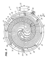
- FIG. 2 shows a radiant heating element with a total of four heating resistors, while in FIG. 3 three heating resistors are provided. They are all connected in parallel to one another, with four (FIG. 2) or three (FIG. 3) adjacent connections being connected to a loop branch.
- the heating resistor arrangement is thus made such that, when connected in parallel, half of the connections with the same polarity lie directly next to each other and is therefore possible with a ring line without skipping a connection.
- a temperature limiter 25 with a limiter and a signal contact protrudes with its rod-shaped sensor 26 diametrically over the entire heating area 21 and through recesses in the edge 19 and the carrier shell 13. It covers the entire heated area very well because of the uniform distribution of the heating resistance.
- heating resistors are spiral-like and in the form of double spirals, of which there are two types in the examples shown. 2 and 3, although all heating resistors can consist of the same and possibly the same length of wire coils, for illustration these two types of heating resistors are marked with different lines, namely a narrow double spiral 30 with a dash-dotted line and one wide double spiral 31 with a dashed line.
- the narrow double spiral 30 begins at two connections 20a, 20b which are adjacent to one another, namely in the associated circumferential position of 45 ° (with eight connections on the circumference) separated from one another, but without other connections lying between them.
- the spiral sections 27, 28 of the double spiral run spirally inwards parallel to one another, their curvature increasing uniformly and continuously according to the spiral shape into a central region 29. In the central region, the two spiral sections 27, 28 move away from each other somewhat and are connected to one another by means of a reversing curve 32, which has approximately a 180 curvature.
- the narrow double spiral 30 is surrounded by a wide double spiral 31. It begins at connections 20c and 20d, which are each with the 1/8 circumferential distance on both sides of connections 20a and 20b. Their spiral sections 27, 28 each run on both sides of the corresponding spiral sections of the inner double spiral 30 in parallel.
- the initially constant distance between the spiral sections 27 of the two double arches in the central region 29 increases and the corresponding reversing arch 32 is significantly larger.
- two such narrow and wide double spirals are interleaved in such a way that in the central region the reversing arches and the inner spiral sections (28 in the case of the double spiral 31 indicated by the broken line) describe the shape of two nested S, in the reversing arches of which 32 each the reversal curve 32 of the narrow double spiral 30 is located.
- the double spirals each describe with their outer spiral section a spiral arc of slightly over 360 °, while the inner spiral arc 28 also describes 45 °.
- a total of eight parallel spiral sections are provided up to the middle.
- connection options in the heating resistor arrangement result in such a way that the connections 20a and 20c are located on one ring line branch 22, while the other connections 20b and 20d of the double spirals are located on the ring line branch 23 with the other polarity.
- the spiral arrangement of the heating resistors is not only very useful and visually appealing, but is also in a certain way symmetrical to almost all diametrical cutting planes, albeit offset in mirror image. From a mathematical point of view, it is point symmetrical to the center of the heating element. This symmetry also makes it possible to install the radiator in any position without visually disturbing it.
- the heating element according to FIG. 3 is basically constructed in the same way as that according to FIG. 2. Because of its smaller diameter, three heating resistors are sufficient here. Accordingly, there are evenly offset by 60, a total of six connections are provided on the outer circumference.
- two narrow double spirals 30 are provided, in the middle of which there is a wide double spiral 31, which, according to the fact that it comprises the two reversing arches 32 of the narrow double spiral 30 with its central region, has a symmetrical S-curvature with two im has the same radius successively arranged reversing arches 32.
- the curvature of each spiral section of the wide double spiral increases so much towards the inside that it becomes equal to that of the reversing curve 32.
- the wide double spiral 31 is fully symmetrical insofar as its connections 20c and 20d are diametrically opposite one another. This is the case with any arrangement with an odd number of double spirals. Versions with any number of double spirals in even and odd numbers are possible.
- Another great advantage is the small number of sharp arcs, which are always particularly thermally at risk. It is also advantageous that not only the individual double spirals, but also the individual spiral sections have almost the same length, which also standardizes the glow pattern and simplifies production.
- the tightly sealed output coils of the heating resistors can be of the same length. They also have the same electrical values.
- heating element shapes for example with oval, angular or asymmetrical heating surface shapes to create cooking surfaces with switchable side zones.
- the spirals would not have the almost ideal spiral shape as in the present case.
- the main advantages would also arise there. It is also possible to have the double spirals describe a substantially larger or smaller angle than 360 ° without the optical and practical effect suffering significantly.
- a radiant heating element which, on the surface of an insulating support, contains heating resistors which originate from connections which are arranged at regular intervals on the outer circumference of the heating area and are connected there to semicircular ring lines.
- the heating resistors run in nested double spirals from the outside to the inside, reverse there in reverse arcs and run parallel to the outside again. The result is a very uniform, almost fully symmetrical arrangement, which enables the annealing state to be reached quickly and a uniform glow pattern.
- B. can be summarized at one point or preferably in a ring line surrounding an unheated central zone. In this case, in an embodiment with eight outer connections, as in FIG. 2, eight individual spiral sections would run to the inner ring line.
- the free central zone can e.g. B. for the arrangement of temperature or pot detection sensors may be important.
Landscapes
- Chemical & Material Sciences (AREA)
- Engineering & Computer Science (AREA)
- Ceramic Engineering (AREA)
- Electric Stoves And Ranges (AREA)
- Resistance Heating (AREA)
Applications Claiming Priority (2)
| Application Number | Priority Date | Filing Date | Title |
|---|---|---|---|
| DE4022292 | 1990-07-15 | ||
| DE4022292A DE4022292A1 (de) | 1990-07-15 | 1990-07-15 | Elektrisches strahlungsheizelement |
Publications (2)
| Publication Number | Publication Date |
|---|---|
| EP0467111A2 true EP0467111A2 (fr) | 1992-01-22 |
| EP0467111A3 EP0467111A3 (en) | 1992-08-05 |
Family
ID=6410202
Family Applications (1)
| Application Number | Title | Priority Date | Filing Date |
|---|---|---|---|
| EP19910110444 Withdrawn EP0467111A3 (en) | 1990-07-15 | 1991-06-25 | Electrical radiant heating element |
Country Status (4)
| Country | Link |
|---|---|
| US (1) | US5153413A (fr) |
| EP (1) | EP0467111A3 (fr) |
| JP (1) | JPH04227423A (fr) |
| DE (1) | DE4022292A1 (fr) |
Cited By (1)
| Publication number | Priority date | Publication date | Assignee | Title |
|---|---|---|---|---|
| DE4320214A1 (de) * | 1993-06-18 | 1994-12-22 | Belzig Elektrowaerme Gmbh | Anordnungen elektrischer Verbindungen und Elemente hierfür |
Families Citing this family (9)
| Publication number | Priority date | Publication date | Assignee | Title |
|---|---|---|---|---|
| JP2571686Y2 (ja) * | 1992-08-19 | 1998-05-18 | ニチワ電機株式会社 | 加熱調理器用発熱部の構造 |
| DE19522798A1 (de) * | 1995-06-23 | 1997-01-02 | Ego Elektro Blanc & Fischer | Verfahren zur Herstellung eines Strahlungsheizkörpers und Strahlungsheizkörper |
| GB0126150D0 (en) * | 2001-10-31 | 2002-01-02 | Gw Pharma Ltd | A device method and resistive element for vaporising a substance |
| JP2007044411A (ja) * | 2005-08-12 | 2007-02-22 | Kyushu Electric Power Co Inc | 圧力調理器 |
| KR101450894B1 (ko) * | 2008-03-17 | 2014-10-14 | 엘지전자 주식회사 | 히터홀더 및 이를 포함하는 전기홉 |
| DE102013216290B4 (de) * | 2013-08-16 | 2015-09-03 | E.G.O. Elektro-Gerätebau GmbH | Heizeinrichtung und Verfahren zum Betrieb einer Heizeinrichtung |
| JP6219229B2 (ja) * | 2014-05-19 | 2017-10-25 | 東京エレクトロン株式会社 | ヒータ給電機構 |
| CN106686774B (zh) * | 2017-01-18 | 2020-02-07 | 广东美的厨房电器制造有限公司 | 电热元件及电加热设备 |
| AU2019349982A1 (en) * | 2018-09-25 | 2021-05-20 | Breville Pty Limited | A cooking appliance |
Citations (4)
| Publication number | Priority date | Publication date | Assignee | Title |
|---|---|---|---|---|
| DE1024181B (de) * | 1955-12-30 | 1958-02-13 | Kanthal Ab | Elektrisches Heizgeraet |
| DE3247028A1 (de) * | 1982-12-18 | 1984-06-20 | Ego Elektro Blanc & Fischer | Temperaturregeleinrichtung fuer ein waermegeraet |
| FR2539940A3 (fr) * | 1983-01-21 | 1984-07-27 | Irca Spa | Element de chauffage electrique, en particulier pour surfaces de cuisson lisses |
| EP0303854A1 (fr) * | 1987-08-18 | 1989-02-22 | E.G.O. Elektro-Geräte Blanc u. Fischer | Radiateur électrique |
Family Cites Families (9)
| Publication number | Priority date | Publication date | Assignee | Title |
|---|---|---|---|---|
| US1348648A (en) * | 1916-10-23 | 1920-08-03 | Sherman L Kelly | Electric heating element and wiring therefor |
| US1417154A (en) * | 1920-07-15 | 1922-05-23 | Steatite Electric Products Cor | Electric heating apparatus |
| US1534673A (en) * | 1923-01-10 | 1925-04-21 | William W Weir | Electrical heating element |
| DE3204760A1 (de) * | 1982-02-11 | 1983-08-18 | Licentia Patent-Verwaltungs-Gmbh, 6000 Frankfurt | Kochfeld aus glaskeramischem material mit einem strahlungsheizkoerper |
| DE3315438A1 (de) * | 1983-04-28 | 1984-10-31 | E.G.O. Elektro-Geräte Blanc u. Fischer, 7519 Oberderdingen | Heizelement zur beheizung von koch-, heizplatten oder dgl. |
| DE3541839A1 (de) * | 1985-11-27 | 1987-06-04 | Ako Werke Gmbh & Co | Strahlungsheizvorrichtung fuer kochplatten |
| EP0234373A3 (fr) * | 1986-02-26 | 1988-03-02 | E.G.O. Elektro-Geräte Blanc u. Fischer | Unité de cuisson avec élément chauffant radiant |
| DE3622415A1 (de) * | 1986-07-03 | 1988-01-07 | Ego Elektro Blanc & Fischer | Strahlheizkoerper |
| DE8706277U1 (de) * | 1987-05-01 | 1987-06-25 | E.G.O. Elektro-Geräte Blanc u. Fischer, 7519 Oberderdingen | Elektrischer Strahlungsheizkörper zur Beheizung einer Platte, insbesondere einer Glaskeramikplatte |
-
1990
- 1990-07-15 DE DE4022292A patent/DE4022292A1/de not_active Withdrawn
-
1991
- 1991-06-25 EP EP19910110444 patent/EP0467111A3/de not_active Withdrawn
- 1991-07-12 US US07/729,367 patent/US5153413A/en not_active Expired - Fee Related
- 1991-07-15 JP JP3174005A patent/JPH04227423A/ja not_active Withdrawn
Patent Citations (4)
| Publication number | Priority date | Publication date | Assignee | Title |
|---|---|---|---|---|
| DE1024181B (de) * | 1955-12-30 | 1958-02-13 | Kanthal Ab | Elektrisches Heizgeraet |
| DE3247028A1 (de) * | 1982-12-18 | 1984-06-20 | Ego Elektro Blanc & Fischer | Temperaturregeleinrichtung fuer ein waermegeraet |
| FR2539940A3 (fr) * | 1983-01-21 | 1984-07-27 | Irca Spa | Element de chauffage electrique, en particulier pour surfaces de cuisson lisses |
| EP0303854A1 (fr) * | 1987-08-18 | 1989-02-22 | E.G.O. Elektro-Geräte Blanc u. Fischer | Radiateur électrique |
Cited By (1)
| Publication number | Priority date | Publication date | Assignee | Title |
|---|---|---|---|---|
| DE4320214A1 (de) * | 1993-06-18 | 1994-12-22 | Belzig Elektrowaerme Gmbh | Anordnungen elektrischer Verbindungen und Elemente hierfür |
Also Published As
| Publication number | Publication date |
|---|---|
| US5153413A (en) | 1992-10-06 |
| JPH04227423A (ja) | 1992-08-17 |
| DE4022292A1 (de) | 1992-01-16 |
| EP0467111A3 (en) | 1992-08-05 |
Similar Documents
| Publication | Publication Date | Title |
|---|---|---|
| EP0531987B1 (fr) | Dispositif de chauffage électrique | |
| EP0124778B1 (fr) | Plaque électrique de cuisinière ou plaque chauffante | |
| EP0590315B1 (fr) | Elément chauffant, en particulier pour appareils de cuisine | |
| DE2205132C3 (de) | Elektrokochgerät | |
| AT398874B (de) | Elektrische strahlungsheizeinrichtung für kochgeräte mit ebener kochfläche | |
| EP0103741B1 (fr) | Elément chauffant, en particulier élément chauffant radiant pour le chauffage de plaques en céramique | |
| DE2518949A1 (de) | Glaskeramik-kochfeld mit filmheizelement | |
| EP2574146B1 (fr) | Dispositif de chauffage à induction et champ de cuisson à induction avec plusieurs dispositifs de chauffage à induction de ce type | |
| DE3410442A1 (de) | Temperaturfuehler, insbesondere fuer einen temperaturbegrenzer fuer eine glaskeramik-kocheinheit | |
| DE3126989A1 (de) | Kochplatte | |
| EP0467111A2 (fr) | Elément chauffant radiant électrique | |
| DE19604218C2 (de) | Heizgerät mit einem PTC-Element und einem Profilkontaktkörper | |
| DE2729929B2 (de) | Strahlungs-Heizeinheit für Glaskeramik-Elektrokochgeräte | |
| EP0303854B1 (fr) | Radiateur électrique | |
| EP0223966B1 (fr) | Dispositif de chauffage par rayonnement pour plaque de cuisson | |
| EP3598848B2 (fr) | Table de cuisson | |
| EP2943044B1 (fr) | Élément thermique d'appareil de cuisson et appareil de cuisson, en particulier table de cuisson | |
| DE2820138C2 (fr) | ||
| DE3810586A1 (de) | Beheizung fuer elektrische kochgeraete | |
| DE69405834T2 (de) | Elektrischer Wärmestrahler | |
| DE102018205970A1 (de) | Heizkörper für ein Gargerät und Gargerät | |
| DE3601634C2 (de) | Vorrichtung zum Regeln oder Begrenzen der Temperatur von Strahlungs- oder Kontaktheizkörpern | |
| EP0714223B1 (fr) | Corps de chauffe rayonnant | |
| EP0163106B1 (fr) | Plaque de cuisson électrique | |
| DE102021202613A1 (de) | Heizeinrichtung für ein Kochfeld und Kochfeld |
Legal Events
| Date | Code | Title | Description |
|---|---|---|---|
| PUAI | Public reference made under article 153(3) epc to a published international application that has entered the european phase |
Free format text: ORIGINAL CODE: 0009012 |
|
| AK | Designated contracting states |
Kind code of ref document: A2 Designated state(s): AT CH DE ES FR GB IT LI SE |
|
| PUAL | Search report despatched |
Free format text: ORIGINAL CODE: 0009013 |
|
| AK | Designated contracting states |
Kind code of ref document: A3 Designated state(s): AT CH DE ES FR GB IT LI SE |
|
| 17P | Request for examination filed |
Effective date: 19921124 |
|
| STAA | Information on the status of an ep patent application or granted ep patent |
Free format text: STATUS: THE APPLICATION HAS BEEN WITHDRAWN |
|
| 18W | Application withdrawn |
Withdrawal date: 19940525 |