EP0467111A2 - Electrical radiant heating element - Google Patents
Electrical radiant heating element Download PDFInfo
- Publication number
- EP0467111A2 EP0467111A2 EP91110444A EP91110444A EP0467111A2 EP 0467111 A2 EP0467111 A2 EP 0467111A2 EP 91110444 A EP91110444 A EP 91110444A EP 91110444 A EP91110444 A EP 91110444A EP 0467111 A2 EP0467111 A2 EP 0467111A2
- Authority
- EP
- European Patent Office
- Prior art keywords
- heating element
- spiral
- connections
- double
- heating
- Prior art date
- Legal status (The legal status is an assumption and is not a legal conclusion. Google has not performed a legal analysis and makes no representation as to the accuracy of the status listed.)
- Withdrawn
Links
Images

Classifications
-
- H—ELECTRICITY
- H05—ELECTRIC TECHNIQUES NOT OTHERWISE PROVIDED FOR
- H05B—ELECTRIC HEATING; ELECTRIC LIGHT SOURCES NOT OTHERWISE PROVIDED FOR; CIRCUIT ARRANGEMENTS FOR ELECTRIC LIGHT SOURCES, IN GENERAL
- H05B3/00—Ohmic-resistance heating
- H05B3/68—Heating arrangements specially adapted for cooking plates or analogous hot-plates
- H05B3/74—Non-metallic plates, e.g. vitroceramic, ceramic or glassceramic hobs, also including power or control circuits
- H05B3/748—Resistive heating elements, i.e. heating elements exposed to the air, e.g. coil wire heater
-
- H—ELECTRICITY
- H05—ELECTRIC TECHNIQUES NOT OTHERWISE PROVIDED FOR
- H05B—ELECTRIC HEATING; ELECTRIC LIGHT SOURCES NOT OTHERWISE PROVIDED FOR; CIRCUIT ARRANGEMENTS FOR ELECTRIC LIGHT SOURCES, IN GENERAL
- H05B2203/00—Aspects relating to Ohmic resistive heating covered by group H05B3/00
- H05B2203/016—Heaters using particular connecting means
Definitions
- the invention relates to an electric radiant heating element, in particular for heating cooking surfaces, such as glass ceramic plates, with a support made of insulating material and heating resistors with connections arranged spirally thereon in a heating area.
- Such a radiant heating element has become known from DE-A-33 15 438.
- the heating resistors run in a double spiral, which has internal and external connections. These lie directly next to each other on essentially the same radius. This creates an asymmetry, i. H. a deviation from the ideal spiral shape, which increases the more parallel spirals are used. This can also be seen from DE-A-36 22 415 and DE-U-87 06 277 and DE-U-87 11 209.
- the object of the invention is to provide a radiant heating element which, in a practical arrangement, enables uniform heating surface coverage.
- connections of all heating resistors ending at the outer edge of the heating region are arranged at circumferential distances from one another distributed over the circumference.
- the one, narrow double spiral has a tighter reversing curve in the central region of the essentially circular heating element and two spiral sections which run directly adjacent to one another and which end in two connections which, although in the circumferential direction, are preferably equally spaced from one another, but are adjacent to one another.
- the other type of double spiral referred to as a wide double spiral, has two reversing arches arranged in the manner of an S and lying next to one another, from which the spiral sections run outwards. At least one narrow double spiral is arranged between them.
- a plurality of interlocking double spirals can be arranged in such a way that they run essentially parallel and at a smaller distance from each other in the heating area than in the central area. This meets the demands for practical heating because the central zone should be less heated. This arrangement is also visually extremely appealing, which is particularly important because the glow pattern shines through the glass ceramic plate and thus also determines the look of a kitchen furniture. An almost fully symmetrical arrangement is created that makes sense and it is.
- All connections can be made from the outside. It is possible to operate two or more heating resistors in parallel, which benefits rapid heating. This also makes it possible to use a particularly highly insulating insulating material, which is usually not mechanically rigid and therefore does not allow direct connections from below to the central area. All connections can be supplied evenly with a ring line consisting of two ring halves running over the carrier surface or in its edge area or even covered by the edge. The arrangement is such that the connections for each polarity are in succession on one side, that is, all connections on one side can be on the same wiring harness.
- each radiant heater contains only two narrow double spirals that have adjacent connections, while the other double spirals are wide spirals, the connections of which adjoin the outside of the connections of the narrow double spirals, so that each polarity lies on one side. It is therefore possible to provide several heating resistors connected in parallel, which leads to a quick glow. In this case, the regulation of the radiant heating element by clocking, i.e. H. pulsed switching on and off.
- heating resistors individually and, for example, to switch them in a multi-cycle circuit (e.g. every seven cycles), in which case control is carried out by combining individual, parallel and series connection of the individual heating resistors.
- a control with two or more heating circuits, which are switched differently by a controller, can also be useful.
- a radiant heating element 11 is arranged below a glass ceramic plate 12 of a cooking appliance to be heated, for example a hob or a cooker, and is pressed resiliently onto the underside thereof.
- the radiant heating element has in a flat carrier shell 13 made of sheet metal a carrier 14 made of insulating material, which consists of a pressed-in layer of a highly heat-insulating, temperature-resistant and also electrically insulating material, for example a pyrogenic silica airgel, which is a relatively looser bulk material, optionally after pre-pressing, into the Shell is introduced and pressed there parallel to the flat bottom 15 of the shell.
- Grooves 17 can be pressed into the surface 16 of the carrier and lead to a part of helical heating resistors 18 consisting of electrical resistance wire, which are arranged on this surface 16 and there by pressing, nailing by means of clips driven into the carrier 14 or the like. are set.
- a peripheral edge 19 made of other insulating material.
- it can be made from a pressed insulating material containing mineral fibers, which is mechanically stronger than the material of the carrier 14, but has lower thermal insulating properties.
- the upper edge of the edge 19 is supported on the glass ceramic plate 12.
- the connections 20 of the heating resistors 18 are all arranged on the outer circumference of the heating region 21 formed within the edge 19, in each case distributed over the circumference at the same circumferential distance (FIGS. 2 and 3). They are connected to a ring line which consists of two ring line branches 22, 23. It lies between the edge and the carrier 14 in a groove 37, so that it is also covered in an electrically insulating manner.
- the ring line branches 22, 23 each encompassing almost half the circumference of the heating element can be connected to supply lines via a connecting piece 24.
- the heating resistors 18 can be connected to the ring line via welding hooks or pins 38 or directly.
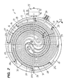
- FIG. 2 shows a radiant heating element with a total of four heating resistors, while in FIG. 3 three heating resistors are provided. They are all connected in parallel to one another, with four (FIG. 2) or three (FIG. 3) adjacent connections being connected to a loop branch.
- the heating resistor arrangement is thus made such that, when connected in parallel, half of the connections with the same polarity lie directly next to each other and is therefore possible with a ring line without skipping a connection.
- a temperature limiter 25 with a limiter and a signal contact protrudes with its rod-shaped sensor 26 diametrically over the entire heating area 21 and through recesses in the edge 19 and the carrier shell 13. It covers the entire heated area very well because of the uniform distribution of the heating resistance.
- heating resistors are spiral-like and in the form of double spirals, of which there are two types in the examples shown. 2 and 3, although all heating resistors can consist of the same and possibly the same length of wire coils, for illustration these two types of heating resistors are marked with different lines, namely a narrow double spiral 30 with a dash-dotted line and one wide double spiral 31 with a dashed line.
- the narrow double spiral 30 begins at two connections 20a, 20b which are adjacent to one another, namely in the associated circumferential position of 45 ° (with eight connections on the circumference) separated from one another, but without other connections lying between them.
- the spiral sections 27, 28 of the double spiral run spirally inwards parallel to one another, their curvature increasing uniformly and continuously according to the spiral shape into a central region 29. In the central region, the two spiral sections 27, 28 move away from each other somewhat and are connected to one another by means of a reversing curve 32, which has approximately a 180 curvature.
- the narrow double spiral 30 is surrounded by a wide double spiral 31. It begins at connections 20c and 20d, which are each with the 1/8 circumferential distance on both sides of connections 20a and 20b. Their spiral sections 27, 28 each run on both sides of the corresponding spiral sections of the inner double spiral 30 in parallel.
- the initially constant distance between the spiral sections 27 of the two double arches in the central region 29 increases and the corresponding reversing arch 32 is significantly larger.
- two such narrow and wide double spirals are interleaved in such a way that in the central region the reversing arches and the inner spiral sections (28 in the case of the double spiral 31 indicated by the broken line) describe the shape of two nested S, in the reversing arches of which 32 each the reversal curve 32 of the narrow double spiral 30 is located.
- the double spirals each describe with their outer spiral section a spiral arc of slightly over 360 °, while the inner spiral arc 28 also describes 45 °.
- a total of eight parallel spiral sections are provided up to the middle.
- connection options in the heating resistor arrangement result in such a way that the connections 20a and 20c are located on one ring line branch 22, while the other connections 20b and 20d of the double spirals are located on the ring line branch 23 with the other polarity.
- the spiral arrangement of the heating resistors is not only very useful and visually appealing, but is also in a certain way symmetrical to almost all diametrical cutting planes, albeit offset in mirror image. From a mathematical point of view, it is point symmetrical to the center of the heating element. This symmetry also makes it possible to install the radiator in any position without visually disturbing it.
- the heating element according to FIG. 3 is basically constructed in the same way as that according to FIG. 2. Because of its smaller diameter, three heating resistors are sufficient here. Accordingly, there are evenly offset by 60, a total of six connections are provided on the outer circumference.
- two narrow double spirals 30 are provided, in the middle of which there is a wide double spiral 31, which, according to the fact that it comprises the two reversing arches 32 of the narrow double spiral 30 with its central region, has a symmetrical S-curvature with two im has the same radius successively arranged reversing arches 32.
- the curvature of each spiral section of the wide double spiral increases so much towards the inside that it becomes equal to that of the reversing curve 32.
- the wide double spiral 31 is fully symmetrical insofar as its connections 20c and 20d are diametrically opposite one another. This is the case with any arrangement with an odd number of double spirals. Versions with any number of double spirals in even and odd numbers are possible.
- Another great advantage is the small number of sharp arcs, which are always particularly thermally at risk. It is also advantageous that not only the individual double spirals, but also the individual spiral sections have almost the same length, which also standardizes the glow pattern and simplifies production.
- the tightly sealed output coils of the heating resistors can be of the same length. They also have the same electrical values.
- heating element shapes for example with oval, angular or asymmetrical heating surface shapes to create cooking surfaces with switchable side zones.
- the spirals would not have the almost ideal spiral shape as in the present case.
- the main advantages would also arise there. It is also possible to have the double spirals describe a substantially larger or smaller angle than 360 ° without the optical and practical effect suffering significantly.
- a radiant heating element which, on the surface of an insulating support, contains heating resistors which originate from connections which are arranged at regular intervals on the outer circumference of the heating area and are connected there to semicircular ring lines.
- the heating resistors run in nested double spirals from the outside to the inside, reverse there in reverse arcs and run parallel to the outside again. The result is a very uniform, almost fully symmetrical arrangement, which enables the annealing state to be reached quickly and a uniform glow pattern.
- B. can be summarized at one point or preferably in a ring line surrounding an unheated central zone. In this case, in an embodiment with eight outer connections, as in FIG. 2, eight individual spiral sections would run to the inner ring line.
- the free central zone can e.g. B. for the arrangement of temperature or pot detection sensors may be important.
Abstract
Ein Strahlungsheizelement (11) enthält auf der Oberfläche (16) eines Isolierträgers (16) Heizwiderstände (18), die von Anschlüssen (20) ausgehen, die in regelmäßigen Abständen am Außenumfang des Heizbereiches (21) angeordnet und dort an Halbkreis-Ringleitungen (22, 23) angeschlossen sind. Die Heizwiderstände verlaufen in ineinandergeschachtelten Doppelspiralen (30, 31) von außen nach innen, kehren dort in Umkehrbögen (32) um und laufen parallel dazu wieder nach außen. Es ergibt sich eine sehr gleichmäßige, nahezu vollsymmetrische Anordnung, die das schnelle Erreichen des Glühzustandes und ein gleichmäßiges Glühbild ergibt. <IMAGE>A radiant heating element (11) contains on the surface (16) of an insulating support (16) heating resistors (18) which originate from connections (20) which are arranged at regular intervals on the outer circumference of the heating area (21) and there on semicircular ring lines (22 , 23) are connected. The heating resistors run in nested double spirals (30, 31) from the outside to the inside, reverse there in reversing bends (32) and run parallel to the outside again. The result is a very uniform, almost fully symmetrical arrangement, which results in the annealing state being reached quickly and a uniform glow pattern. <IMAGE>
Description
Die Erfindung betrifft ein elektrisches Strahlungsheizelement, insbesondere zur Beheizung von Kochflächen, wie Glaskeramikplatten, mit einem Träger aus Isoliermaterial und darauf in einem Heizbereich spiralartig angeordneten Heizwiderständen mit Anschlüssen.The invention relates to an electric radiant heating element, in particular for heating cooking surfaces, such as glass ceramic plates, with a support made of insulating material and heating resistors with connections arranged spirally thereon in a heating area.
Ein solches Strahlungsheizelement ist aus der DE-A-33 15 438 bekanntgeworden. Dabei verlaufen die Heizwiderstände in einer Doppelspirale, die innere und äußere Anschlüsse hat. Diese liegen direkt nebeneinander im wesentlichen auf dem gleichen Radius. Es entsteht dadurch eine Unsymmetrie, d. h. eine Abweichung von der idealen Spiralform, die um so größer wird, je mehr parallele Spiralen verwendet werden. Dies ist auch aus der DE-A-36 22 415 und dem DE-U-87 06 277 sowie DE-U-87 11 209 zu erkennen.Such a radiant heating element has become known from DE-A-33 15 438. The heating resistors run in a double spiral, which has internal and external connections. These lie directly next to each other on essentially the same radius. This creates an asymmetry, i. H. a deviation from the ideal spiral shape, which increases the more parallel spirals are used. This can also be seen from DE-A-36 22 415 and DE-U-87 06 277 and DE-U-87 11 209.
Es ist ferner bekanntgeworden, anstatt von spiraliger Anordnung die Heizwiderstände in Form von Doppelbögen zu verlegen, die teilweise offen sind und in einen Mittelbereich eingreifende "Auswüchse" haben. Diese Anordnung ermöglicht es zwar, Anschlüsse weitgehend vom Randbereich aus zu beschicken, ohne daß sie Heizwiderstände überqueren oder unterlaufen müssen, ist jedoch optisch unschön und schwierig zu verlegen, insbesondere wegen vieler nötiger enger 180 -Bögen.It has also become known, instead of laying the heating resistors in the form of double arches, which are partially open and have "protrusions" engaging in a central region, instead of being laid out in a spiral arrangement. Although this arrangement makes it possible to feed connections largely from the edge area without having to cross or undercut heating resistors, it is optically unattractive and difficult to install, in particular because of the many necessary narrow 180 arches.
Aufgabe der Erfindung ist es, ein Strahlheizelement zu schaffen, das in einer sinnfälligen Anordnung eine gleichmäßige Heizflächenüberdeckung ermöglicht.The object of the invention is to provide a radiant heating element which, in a practical arrangement, enables uniform heating surface coverage.
Dies wird erfindungsgemäß dadurch gelöst, daß die am Außenrand des Heizbereiches endenden Anschlüsse aller Heizwiderstände in Umfangsabständen voneinander über den Umfang verteilt angeordnet sind.This is achieved according to the invention in that the connections of all heating resistors ending at the outer edge of the heating region are arranged at circumferential distances from one another distributed over the circumference.
Es ergibt sich dadurch eine Anordnung von zueinander parallelen Spiralen, die etwa im gleichen Abstand voneinander verlaufen und eine von außen nach innen stetig zunehmende Krümmung haben, bis sie in einem oder zwei Umkehrbögen ihre Richtung wechseln und wieder nach außen verlaufen.This results in an arrangement of mutually parallel spirals, which run approximately at the same distance from one another and have a continuously increasing curvature from the outside in until they change direction in one or two reversing arcs and run out again.
Dabei entstehen zwei Doppelspiralentypen. Die eine, enge Doppelspirale hat einen engeren Umkehrbogen im Mittelbereich des im wesentlichen kreisförmigen Heizelementes und zwei parallel zueinander unmittelbar benachbart verlaufende Spiralabschnitte, die in zwei Anschlüssen enden, die zwar in Umfangsrichtung einen vorzugsweise gleichen Abstand voneinander haben, jedoch benachbart zueinander sind. Der andere, als weite Doppelspirale bezeichnete Doppelspiralentyp hat zwei nach Art eines S angeordnete und nebeneinanderliegende Umkehrbögen, von denen die Spiralabschnitte nach außen verlaufen. Zwischen diesen ist jeweils wenigstens eine enge Doppelspirale angeordnet.This creates two types of double spirals. The one, narrow double spiral has a tighter reversing curve in the central region of the essentially circular heating element and two spiral sections which run directly adjacent to one another and which end in two connections which, although in the circumferential direction, are preferably equally spaced from one another, but are adjacent to one another. The other type of double spiral, referred to as a wide double spiral, has two reversing arches arranged in the manner of an S and lying next to one another, from which the spiral sections run outwards. At least one narrow double spiral is arranged between them.
Es können so mehrere ineinandergreifende Doppelspiralen so angeordnet werden, daß sie im Heizbereich im wesentlichen parallel und mit geringerem Abstand zueinander verlaufen, als im Mittelbereich. Dies kommt den Forderungen nach einer praxisgerechten Beheizung sehr entgegen, weil die Mittelzone schwächer beheizt sein sollte. Diese Anordnung ist auch optisch außerordentlich ansprechend, was besonders wichtig ist, weil das Glühbild durch die Glaskeramikplatte durchscheint und damit auch die Optik eines Küchenmöbels bestimmt. Es wird eine nahezu vollsymmetrische Anordnung geschaffen, die sinnvoll wirkt und es auch ist.A plurality of interlocking double spirals can be arranged in such a way that they run essentially parallel and at a smaller distance from each other in the heating area than in the central area. This meets the demands for practical heating because the central zone should be less heated. This arrangement is also visually extremely appealing, which is particularly important because the glow pattern shines through the glass ceramic plate and thus also determines the look of a kitchen furniture. An almost fully symmetrical arrangement is created that makes sense and it is.
Alle Anschlüsse können von der Außenseite her vorgenommen werden. Es ist möglich, so zwei oder mehr Heizwiderstände parallel zu betreiben, was einer schnellen Aufheizung zugute kommt. Es ist dadurch auch möglich, ein besonders hoch wärmedämmendes Isoliermaterial zu verwenden, was meist mechanisch wenig fest ist und daher es nicht erlaubt, ohne weiteres Anschlüsse von unten her in den Mittelbereich zu leiten. Mit einer über der Trägeroberfläche bzw. in deren Randbereich oder sogar vom Rand abgedeckt laufenden Ringleitung aus zwei Ringhälften können alle Anschlüsse gleichmäßig versorgt werden. Die Anordnung ist dabei so getroffen, daß jeweils die Anschlüsse für jede Polarität in Folge auf einer Seite liegen, also alle Anschlüsse einer Seite an dem gleichen Leitungsstrang liegen können. Dies ist dadurch möglich, daß jeder Strahlheizkörper nur zwei enge Doppelspiralen enthält, die nebeneinanderliegende Anschlüsse haben, während die übrigen Doppelspiralen weite Spiralen sind, deren Anschlüsse jeweils außen an die Anschlüsse der engen Doppelspiralen angrenzen, so daß jede Polarität auf einer Seite liegt. Es ist also möglich, mehrere parallel geschaltete Heizwiderstände vorzusehen, was zu einem schnellen Glühen führt. In diesem Falle würde die Regelung des Strahlheizelementes durch Takten, d. h. impulsweises Ein- und Ausschalten erfolgen.All connections can be made from the outside. It is possible to operate two or more heating resistors in parallel, which benefits rapid heating. This also makes it possible to use a particularly highly insulating insulating material, which is usually not mechanically rigid and therefore does not allow direct connections from below to the central area. All connections can be supplied evenly with a ring line consisting of two ring halves running over the carrier surface or in its edge area or even covered by the edge. The arrangement is such that the connections for each polarity are in succession on one side, that is, all connections on one side can be on the same wiring harness. This is possible because each radiant heater contains only two narrow double spirals that have adjacent connections, while the other double spirals are wide spirals, the connections of which adjoin the outside of the connections of the narrow double spirals, so that each polarity lies on one side. It is therefore possible to provide several heating resistors connected in parallel, which leads to a quick glow. In this case, the regulation of the radiant heating element by clocking, i.e. H. pulsed switching on and off.
Es ist jedoch auch möglich, die Heizwiderstände einzeln anzuschließen und beispielsweise in Mehrtakt-Schaltung (z. B. im Siebentakt) zu schalten, wobei dann durch Kombination von Einzel-, Parallel- und Reihenschaltung der einzelnen Heizwiderstände eine Steuerung erfolgt. Auch eine Regelung mit zwei oder mehr Heizkreisen, die von einem Regler unterschiedlich geschaltet werden, kann sinnvoll sein, um so z. B. eine Weiterkoch-Dauerleistung mit einem Heizwiderstand zu fahren und die anderen dann zuzuschalten, wenn die abzunehmende Leistung größer wird. Dies kann beispielsweise über einen Temperaturregler mit zwei oder mehr auf unterschiedliche Temperaturen justierten Schaltkontakten erfolgen. In jedem Falle bleibt aber die gute Heizleitstungsverteilung über die Fläche erhalten und auch der gute optische Gesamteindruck.However, it is also possible to connect the heating resistors individually and, for example, to switch them in a multi-cycle circuit (e.g. every seven cycles), in which case control is carried out by combining individual, parallel and series connection of the individual heating resistors. A control with two or more heating circuits, which are switched differently by a controller, can also be useful. B. to continue cooking continuous power with a heating resistor and then turn on the others when the power to be decreased is greater. This can be done, for example, using a temperature controller with two or more switching contacts adjusted to different temperatures. In any case, however, the good heating cable distribution over the surface and the good optical appearance are retained Overall impression.
Diese und weitere Merkmale der Erfindung gehen außer aus den Ansprüchen auch aus der Beschreibung und den Zeichnungen hervor, wobei die einzelnen Merkmale jeweils für sich allein oder zu mehreren in Form von Unterkombinationen bei einer Ausführungsform der Erfindung und auf anderen Gebieten verwirklicht sein und vorteilhafte sowie für sich schutzfähige Ausführungen darstellen können, für die hier Schutz beansprucht wird. Ein Ausführungsbeispiel der Erfindung ist in den Zeichnungen dargestellt und wird im folgenden näher erläutert. In den Zeichnungen zeigen:
- Fig. 1 einen schematischen Querschnitt durch einen Strahlheizkörper nach Linie in Fig. 2 und
- Fig. 2 und 3 je eine Draufsicht auf ein Strahlheizelement.
- Fig. 1 shows a schematic cross section through a radiant heater according to the line in Fig. 2 and
- 2 and 3 are each a top view of a radiant heating element.
Ein Strahlheizelement 11 ist unterhalb einer zu beheizenden Glaskeramikplatte 12 eines Kochgerätes, beispielsweise einer Kochmulde oder eines Kochherdes, angeordnet und federnd an dessen Unterseite angedrückt. Das Strahlheizelement hat in einer flachen Trägerschale 13 aus Blech einen Träger 14 aus Isoliermaterial, der aus einer eingepreßten Schicht aus einem hochwärmedämmenden, temperaturbeständigen und auch elektrisch isolierenden Material besteht, beispielsweise einem pyrogenen Kieselsäureaerogel, das als relativ lokkeres Schüttmaterial, gegebenenfalls nach Vorpressung, in die Schale eingebracht und dort parallel zum ebenen Boden 15 der Schale eingepreßt wird. In die Oberfläche 16 des Trägers können Nuten 17 eingepreßt sein, die einen Teil von wendelförmigen, aus elektrischem Widerstandsdraht bestehenden Heizwiderständen 18 führen, die auf dieser Oberfläche 16 angeordnet sind und dort durch Einpressen, Festnageln mittels in den Träger 14 eingetriebener Klammern o. dgl. festgelegt sind.A
Auf der Oberfläche des Trägers 14 liegt ein umlaufender Rand 19 aus anderem Isoliermaterial. Es kann beispielsweise aus einem gepreßten, mineralische Fasern enthaltenden Isoliermaterial hergestellt sein, das mechanisch fester ist als das Material des Trägers 14, dafür jedoch geringere thermische Isoliereigenschaften aufweist. Die Oberkante des Randes 19 stützt sich an der Glaskeramikplatte 12 ab.On the surface of the
Die Anschlüsse 20 der Heizwiderstände 18 sind alle am Außenumfang des innerhalb des Randes 19 gebildeten Heizbereiches 21 angeordnet, und zwar jeweils mit gleichem Umfangsabstand über den Umfang verteilt (Fig. 2 und 3). Sie sind an eine Ringleitung angeschlossen, die aus zwei Ringleitungszweigen 22, 23 besteht. Sie liegt zwischen dem Rand und dem Träger 14 in einer Nut 37, so daß sie auch elektrisch isolierend abgedeckt ist. Die jeweils knapp den halben Heizelementumfang umfassende Ringleitungszweige 22, 23 sind über ein Anschlußstück 24 an Zuleitungen anschließbar. Der Anschluß der Heizwiderstände 18 an die Ringleitung kann über Anschweißhaken oder Stifte 38 oder auch unmittelbar erfolgen.The
Fig. 2 zeigt ein Strahlheizelement mit insgesamt vier Heizwiderständen, während in Fig. 3 drei Heizwiderstände vorgesehen sind. Sie sind alle parallel zueinander geschaltet, wobei jeweils vier (Fig. 2) bzw. drei (Fig. 3) nebeneinanderliegende Anschlüsse an einen Ringleitungszweig angeschlossen sind. Die Heizwiderstandsanordnung ist also so getroffen, daß bei Parallelschaltung jeweils die Hälfte der Anschlüsse mit der gleichen Polarität unmittelbar nebeneinanderliegen und somit mit einer Ringleitung ohne Überspringen eines Anschlusses möglich ist.FIG. 2 shows a radiant heating element with a total of four heating resistors, while in FIG. 3 three heating resistors are provided. They are all connected in parallel to one another, with four (FIG. 2) or three (FIG. 3) adjacent connections being connected to a loop branch. The heating resistor arrangement is thus made such that, when connected in parallel, half of the connections with the same polarity lie directly next to each other and is therefore possible with a ring line without skipping a connection.
Ein Temperaturbegrenzer 25 mit einem Begrenzer- und einem Signalkontakt ragt mit seinem stabförmigen Fühler 26 diametral über den gesamten Heizbereich 21 und durch Ausnehmungen in dem Rand 19 und der Trägerschale 13. Er erfaßt wegen der gleichmäßigen Heizwiderstandsverteilung die gesamte beheizte Fläche bestens.A temperature limiter 25 with a limiter and a signal contact protrudes with its rod-
Die gesamte Anordnung der Heizwiderstände ist spiralartig und zwar in Form von Doppelspiralen, von denen es in den dargestellten Beispielen zwei Typen gibt. In Fig. 2 und 3 sind, obwohl alle Heizwiderstände aus gleichen und ggf. in der Drahtlänge gleich langen Drahtwendeln bestehen können, zur Veranschaulichung diese beiden Typen von Heizwiderständen mit einer unterschiedlichen Linienführung gekennzeichnet, und zwar eine enge Doppelspirale 30 mit einer strichpunktierten Linie und eine weite Doppelspirale 31 mit einer strichlierten Linie.The entire arrangement of the heating resistors is spiral-like and in the form of double spirals, of which there are two types in the examples shown. 2 and 3, although all heating resistors can consist of the same and possibly the same length of wire coils, for illustration these two types of heating resistors are marked with different lines, namely a narrow
Die enge Doppelspirale 30 beginnt an zwei Anschlüssen 20a, 20b, die nebeneinanderliegen, und zwar im ihnen zugehörigen Umfangsstand von 45° (bei acht Anschlüssen am Umfang) voneinander getrennt, ohne daß jedoch andere Anschlüsse dazwischenliegen. Die Spiralabschnitte 27, 28 der Doppelspirale laufen parallel zueinander spiralig nach innen, wobei ihre Krümmung entsprechend der Spiralform gleichmäßig und stetig bis in einen Mittelbereich 29 zunimmt. Im Mittelbereich entfernen sich die beiden Spiralabschnitte 27, 28 etwas voneinander und sind über einen Umkehrbogen 32, der etwa eine 180 -Krümmung hat, miteinander verbunden.The narrow
Die enge Doppelspirale 30 ist von einer weiten Doppelspirale 31 umgeben. Sie beginnt an Anschlüssen 20c und 20d, die jeweils mit dem 1/8-Umfangsabstand zu beiden Seiten der Anschlüsse 20a und 20b liegen. Ihre Spiralabschnitte 27, 28 verlaufen jeweils zu beiden Seiten der entsprechenden Spiralabschnitte der inneren Doppelspirale 30 parallel. Auch hier vergrößert sich der zu Anfang konstante Abstand zwischen den Spiralabschnitten 27 beider Doppelbögen im Mittelbereich 29 und der entsprechende Umkehrbogen 32 ist wesentlich größer.The narrow
Bei dem Strahlheizelelement nach Fig. 2 sind je zwei derartige enge und weite Doppelspiralen so ineinander verschachtelt, daß im Mittelbereich die Umkehrbögen und die daran anschließenden inneren Spiralabschnitte (28 bei der strichliert angedeuteten Doppelspirale 31) die Form zweier ineinander geschachtelter S beschreiben, in deren Umkehrbögen 32 jeweils der Umkehrbogen 32 der engen Doppelspirale 30 liegt. Die Doppelspiralen beschreiben jeweils mit ihrem äußerem Spiralabschnitt einen Spiralbogen von etwas über 360°, während der innere Spiralbogen 28 45° zusätzlich beschreibt. Es entsteht dadurch aufgrund der insgesamt acht Spiralabschnitte eine achtgängige Spirale, deren Heizringbereich, d. h. der vom Mittelbereich 29 gesehen äußere Teil des Heizbereiches 21, zueinander parallel verlaufende Heizwendeln in relativ dichter Anordnung aufweist. Insgesamt sind bis zur Mitte acht parallel verlaufende Spiralabschnitte vorgesehen.In the radiant heating element according to FIG. 2, two such narrow and wide double spirals are interleaved in such a way that in the central region the reversing arches and the inner spiral sections (28 in the case of the
Es ist zu erkennen, daß sich die Anschlußmöglichkeiten bei der Heizwiderstandsanordnung so ergeben, daß die Anschlüsse 20a und 20c an dem einen Ringleitungszweig 22 liegen, während die jeweils anderen Anschlüsse 20b und 20d der Doppelspiralen an dem Ringleitungszweig 23 mit der anderen Polarität liegen.It can be seen that the connection options in the heating resistor arrangement result in such a way that the
Die Spiralanordnung der Heizwiderstände ist nicht nur sehr sinnvoll und optisch ansprechend, sondern ist auch auf eine bestimmte Weise zu fast allen diametralen Schnittebenen symmetrisch, wenn auch jeweils spiegelbildlich versetzt. Er ist, mathematisch betrachtet, punktsymmetrisch zum Heizelement-Mittelpunkt. Diese Symmetrie macht es auch möglich, den Heizkörper in beliebiger Position einzubauen, ohne daß dies optisch stören würde.The spiral arrangement of the heating resistors is not only very useful and visually appealing, but is also in a certain way symmetrical to almost all diametrical cutting planes, albeit offset in mirror image. From a mathematical point of view, it is point symmetrical to the center of the heating element. This symmetry also makes it possible to install the radiator in any position without visually disturbing it.
Das Heizelement nach Fig. 3 ist prinzipiell gleich aufgebaut wie das nach Fig. 2. Infolge seines kleineren Durchmessers genügen hier drei Heizwiderstände. Es sind dementsprechend gleichmäßig um jeweils 60 versetzt, insgesamt sechs Anschlüsse am Außenumfang vorgesehen. Von den drei doppelspiralig angeordneten Heizwiderständen sind zwei enge Doppelspiralen 30 vorgesehen, in deren Mitte eine weite Doppelspirale 31 liegt, die entsprechend der Tatsache, daß sie mit ihrem Mittelbereich die beiden Umkehrbögen 32 der engen Doppelspirale 30 umfaßt, eine symmetrische S-Krümmung mit zwei im gleichen Radius hintereinander angeordneten Umkehrbögen 32 aufweist. Die Krümmung jedes Spiralabschnitts der weiten Doppelspirale nimmt also zum Inneren hin so stark zu, daß sie gleich der des Umkehrbogens 32 wird. Die weite Doppelspirale 31 ist in diesem Fall in sofern voll symmetrisch, als ihre Anschlüsse 20c und 20d einander diametral gegenüberliegen. Dies ist bei jeder Anordnung mit ungerader Anzahl von Doppelspiralen der Fall. Es sind Ausführungen mit beliebig vielen Doppelspiralen in gerader und ungerader Zahl möglich.The heating element according to FIG. 3 is basically constructed in the same way as that according to FIG. 2. Because of its smaller diameter, three heating resistors are sufficient here. Accordingly, there are evenly offset by 60, a total of six connections are provided on the outer circumference. Of the three heating elements arranged in a double spiral, two narrow
Ein großer Vorteil ist auch die geringe Anzahl von scharfen Bögen, die stets thermisch besonders gefährdet sind. Vorteilhaft ist auch, daß nicht nur die einzelnen Doppelspiralen, sondern auch die einzelnen Spiralabschnitte nahezu die gleiche Länge haben, wodurch ebenfalls das Glühbild vereinheitlicht und die Herstellung vereinfacht wird. Die dicht-andicht gewickelten Ausgangswendeln der Heizwiderstände können gleichlang sein. Sie haben auch gleiche elektrische Werte.Another great advantage is the small number of sharp arcs, which are always particularly thermally at risk. It is also advantageous that not only the individual double spirals, but also the individual spiral sections have almost the same length, which also standardizes the glow pattern and simplifies production. The tightly sealed output coils of the heating resistors can be of the same length. They also have the same electrical values.
Entsprechende oder ähnliche Anordnungen sind auch bei anderen Heizelementformen möglich, beispielsweise bei ovalen, eckigen oder zur Schaffung von Kochflächen mit zuschaltbaren Seitenzonen unsymmetrischen Heizflächenformen. In diesem Falle würden die Spiralen nicht die fast ideale Spiralform haben, wie im vorliegenden Fall. Die Hauptvorteile würden sich jedoch auch dort ergeben. Es ist auch möglich, die Doppelspiralen einen wesentlich größeren oder auch kleineren Winkel als 360° beschreiben zu lassen, ohne daß der optische und praktische Effekt darunter wesentlich leidet.Corresponding or similar arrangements are also possible with other heating element shapes, for example with oval, angular or asymmetrical heating surface shapes to create cooking surfaces with switchable side zones. In this case the spirals would not have the almost ideal spiral shape as in the present case. However, the main advantages would also arise there. It is also possible to have the double spirals describe a substantially larger or smaller angle than 360 ° without the optical and practical effect suffering significantly.
Es wird also ein Strahlungsheizelement geschaffen, das auf der Oberfläche eines Isolierträgers Heizwiderstände enthält, die von Anschlüssen ausgehen, die in regelmäßigen Abständen am Außenumfang des Heizbereiches angeordnet und dort an Halbkreis-Ringleitungen angeschlossen sind. Die Heizwiderstände verlaufen in ineinandergeschachtelten Doppelspiralen von außen nach innen, kehren dort in Umkehrbögen um und laufen parallel dazu wieder nach außen. Es ergibt sich eine sehr gleichmäßige, nahezu vollsymmetrische Anordnung, die das schnelle Erreichen des Glühzustandes und ein gleichmäßiges Glühbild ermöglicht.A radiant heating element is thus created which, on the surface of an insulating support, contains heating resistors which originate from connections which are arranged at regular intervals on the outer circumference of the heating area and are connected there to semicircular ring lines. The heating resistors run in nested double spirals from the outside to the inside, reverse there in reverse arcs and run parallel to the outside again. The result is a very uniform, almost fully symmetrical arrangement, which enables the annealing state to be reached quickly and a uniform glow pattern.
Da im Mittelbereich wegen der Parallelschaltung bei allen Heizwiderständen das gleiche Potential vorliegt, können sie dort auch z. B. in einem Punkt oder vorzugsweise in einer eine unbeheizte Mittelzone umgebenden Ringleitung zusammengefaßt werden. In diesem Falle würden also bei einer Ausführung mit acht äußeren Anschlüssen wie in Fig. 2 acht einzelne Spiralabschnitte zur inneren Ringleitung verlaufen. Die freie Mittelzone kann z. B. für die Anordnung von Temperatur- oder Topferkennungsfühlern wichtig sein.Since there is the same potential in the central area due to the parallel connection of all heating resistors, B. can be summarized at one point or preferably in a ring line surrounding an unheated central zone. In this case, in an embodiment with eight outer connections, as in FIG. 2, eight individual spiral sections would run to the inner ring line. The free central zone can e.g. B. for the arrangement of temperature or pot detection sensors may be important.
Claims (11)
Applications Claiming Priority (2)
| Application Number | Priority Date | Filing Date | Title |
|---|---|---|---|
| DE4022292A DE4022292A1 (en) | 1990-07-15 | 1990-07-15 | ELECTRIC RADIATION HEATING ELEMENT |
| DE4022292 | 1990-07-15 |
Publications (2)
| Publication Number | Publication Date |
|---|---|
| EP0467111A2 true EP0467111A2 (en) | 1992-01-22 |
| EP0467111A3 EP0467111A3 (en) | 1992-08-05 |
Family
ID=6410202
Family Applications (1)
| Application Number | Title | Priority Date | Filing Date |
|---|---|---|---|
| EP19910110444 Withdrawn EP0467111A3 (en) | 1990-07-15 | 1991-06-25 | Electrical radiant heating element |
Country Status (4)
| Country | Link |
|---|---|
| US (1) | US5153413A (en) |
| EP (1) | EP0467111A3 (en) |
| JP (1) | JPH04227423A (en) |
| DE (1) | DE4022292A1 (en) |
Cited By (1)
| Publication number | Priority date | Publication date | Assignee | Title |
|---|---|---|---|---|
| DE4320214A1 (en) * | 1993-06-18 | 1994-12-22 | Belzig Elektrowaerme Gmbh | Arrangements of electrical connections and elements therefor |
Families Citing this family (8)
| Publication number | Priority date | Publication date | Assignee | Title |
|---|---|---|---|---|
| JP2571686Y2 (en) * | 1992-08-19 | 1998-05-18 | ニチワ電機株式会社 | Structure of the heating part for the cooking device |
| DE19522798A1 (en) * | 1995-06-23 | 1997-01-02 | Ego Elektro Blanc & Fischer | Process for producing a radiant heater and radiant heater |
| GB0126150D0 (en) * | 2001-10-31 | 2002-01-02 | Gw Pharma Ltd | A device method and resistive element for vaporising a substance |
| JP2007044411A (en) * | 2005-08-12 | 2007-02-22 | Kyushu Electric Power Co Inc | Pressure cooker |
| KR101450894B1 (en) * | 2008-03-17 | 2014-10-14 | 엘지전자 주식회사 | A heater holder and electric hob comprising the same |
| DE102013216290B4 (en) * | 2013-08-16 | 2015-09-03 | E.G.O. Elektro-Gerätebau GmbH | Heating device and method for operating a heating device |
| JP6219229B2 (en) * | 2014-05-19 | 2017-10-25 | 東京エレクトロン株式会社 | Heater feeding mechanism |
| CN106686774B (en) * | 2017-01-18 | 2020-02-07 | 广东美的厨房电器制造有限公司 | Electric heating element and electric heating equipment |
Citations (4)
| Publication number | Priority date | Publication date | Assignee | Title |
|---|---|---|---|---|
| DE1024181B (en) * | 1955-12-30 | 1958-02-13 | Kanthal Ab | Electric heater |
| DE3247028A1 (en) * | 1982-12-18 | 1984-06-20 | Ego Elektro Blanc & Fischer | TEMPERATURE CONTROL DEVICE FOR A HEATER |
| FR2539940A3 (en) * | 1983-01-21 | 1984-07-27 | Irca Spa | ELECTRIC HEATING ELEMENT, PARTICULARLY FOR SMOOTH COOKING SURFACES |
| EP0303854A1 (en) * | 1987-08-18 | 1989-02-22 | E.G.O. Elektro-Geräte Blanc u. Fischer | Radiant heater |
Family Cites Families (9)
| Publication number | Priority date | Publication date | Assignee | Title |
|---|---|---|---|---|
| US1348648A (en) * | 1916-10-23 | 1920-08-03 | Sherman L Kelly | Electric heating element and wiring therefor |
| US1417154A (en) * | 1920-07-15 | 1922-05-23 | Steatite Electric Products Cor | Electric heating apparatus |
| US1534673A (en) * | 1923-01-10 | 1925-04-21 | William W Weir | Electrical heating element |
| DE3204760A1 (en) * | 1982-02-11 | 1983-08-18 | Licentia Patent-Verwaltungs-Gmbh, 6000 Frankfurt | Cooking top made of glass-ceramic material with a radiant heating element |
| DE3315438A1 (en) * | 1983-04-28 | 1984-10-31 | E.G.O. Elektro-Geräte Blanc u. Fischer, 7519 Oberderdingen | HEATING ELEMENT FOR HEATING COOKING, HEATING PLATES OR THE LIKE |
| DE3541839A1 (en) * | 1985-11-27 | 1987-06-04 | Ako Werke Gmbh & Co | RADIATION HEATING DEVICE FOR HOTPLATES |
| EP0234373A3 (en) * | 1986-02-26 | 1988-03-02 | E.G.O. Elektro-Geräte Blanc u. Fischer | Cooking unit with radiant heating element |
| DE3622415A1 (en) * | 1986-07-03 | 1988-01-07 | Ego Elektro Blanc & Fischer | BEAM RADIATOR |
| DE8706277U1 (en) * | 1987-05-01 | 1987-06-25 | E.G.O. Elektro-Geraete Blanc U. Fischer, 7519 Oberderdingen, De |
-
1990
- 1990-07-15 DE DE4022292A patent/DE4022292A1/en not_active Withdrawn
-
1991
- 1991-06-25 EP EP19910110444 patent/EP0467111A3/en not_active Withdrawn
- 1991-07-12 US US07/729,367 patent/US5153413A/en not_active Expired - Fee Related
- 1991-07-15 JP JP3174005A patent/JPH04227423A/en not_active Withdrawn
Patent Citations (4)
| Publication number | Priority date | Publication date | Assignee | Title |
|---|---|---|---|---|
| DE1024181B (en) * | 1955-12-30 | 1958-02-13 | Kanthal Ab | Electric heater |
| DE3247028A1 (en) * | 1982-12-18 | 1984-06-20 | Ego Elektro Blanc & Fischer | TEMPERATURE CONTROL DEVICE FOR A HEATER |
| FR2539940A3 (en) * | 1983-01-21 | 1984-07-27 | Irca Spa | ELECTRIC HEATING ELEMENT, PARTICULARLY FOR SMOOTH COOKING SURFACES |
| EP0303854A1 (en) * | 1987-08-18 | 1989-02-22 | E.G.O. Elektro-Geräte Blanc u. Fischer | Radiant heater |
Cited By (1)
| Publication number | Priority date | Publication date | Assignee | Title |
|---|---|---|---|---|
| DE4320214A1 (en) * | 1993-06-18 | 1994-12-22 | Belzig Elektrowaerme Gmbh | Arrangements of electrical connections and elements therefor |
Also Published As
| Publication number | Publication date |
|---|---|
| US5153413A (en) | 1992-10-06 |
| DE4022292A1 (en) | 1992-01-16 |
| JPH04227423A (en) | 1992-08-17 |
| EP0467111A3 (en) | 1992-08-05 |
Similar Documents
| Publication | Publication Date | Title |
|---|---|---|
| EP0531987B1 (en) | Electrical heating unit | |
| EP0124778B1 (en) | Electric cooking plate or hot plate | |
| DE2205132C3 (en) | Electric cooker | |
| AT398874B (en) | ELECTRIC RADIATION HEATING DEVICE FOR COOKING APPLIANCES WITH LEVEL COOKING SURFACE | |
| EP0103741B1 (en) | Heating element, especially radiant heating element for the heating of ceramic plates | |
| DE2339768C3 (en) | Electric hotplate | |
| DE2518949A1 (en) | GLASS CERAMIC HOB WITH FILM HEATING ELEMENT | |
| EP2574146B1 (en) | Induction heating device and induction hob with several such induction heating facilities | |
| DE3410442A1 (en) | TEMPERATURE PROBE, ESPECIALLY FOR A TEMPERATURE LIMITER FOR A GLASS CERAMIC COOKING UNIT | |
| EP0757210A1 (en) | Radiating cooker element | |
| EP0490289A1 (en) | Electric heater particularly radiant heater | |
| EP0467111A2 (en) | Electrical radiant heating element | |
| DE2729929B2 (en) | Radiant heating unit for glass ceramic electric cookers | |
| EP0303854B1 (en) | Radiant heater | |
| EP0223966B1 (en) | Radiation heating device for a cooking plate | |
| DE19604218C2 (en) | Heater with a PTC element and a profile contact body | |
| DE2820138C2 (en) | ||
| DE102018212094A1 (en) | Heating device for a hob and hob | |
| EP1006320A2 (en) | Electral instantaneous heater and method for making same | |
| EP0175949B1 (en) | Heat generator for heating fluids | |
| DE3810586A1 (en) | Heating system for electric cooking appliances | |
| EP2943044A1 (en) | Heater for a cooking appliance and cooking appliance, in particular a hotplate | |
| DE102018205970A1 (en) | Radiator for a cooking appliance and cooking appliance | |
| DE3914990A1 (en) | RADIATION HEATING DEVICE | |
| DE3601634C2 (en) | Device for regulating or limiting the temperature of radiant or contact radiators |
Legal Events
| Date | Code | Title | Description |
|---|---|---|---|
| PUAI | Public reference made under article 153(3) epc to a published international application that has entered the european phase |
Free format text: ORIGINAL CODE: 0009012 |
|
| AK | Designated contracting states |
Kind code of ref document: A2 Designated state(s): AT CH DE ES FR GB IT LI SE |
|
| PUAL | Search report despatched |
Free format text: ORIGINAL CODE: 0009013 |
|
| AK | Designated contracting states |
Kind code of ref document: A3 Designated state(s): AT CH DE ES FR GB IT LI SE |
|
| 17P | Request for examination filed |
Effective date: 19921124 |
|
| STAA | Information on the status of an ep patent application or granted ep patent |
Free format text: STATUS: THE APPLICATION HAS BEEN WITHDRAWN |
|
| 18W | Application withdrawn |
Withdrawal date: 19940525 |