EP0465846B1 - Kugelpumpe - Google Patents
Kugelpumpe Download PDFInfo
- Publication number
- EP0465846B1 EP0465846B1 EP91109463A EP91109463A EP0465846B1 EP 0465846 B1 EP0465846 B1 EP 0465846B1 EP 91109463 A EP91109463 A EP 91109463A EP 91109463 A EP91109463 A EP 91109463A EP 0465846 B1 EP0465846 B1 EP 0465846B1
- Authority
- EP
- European Patent Office
- Prior art keywords
- bushing
- distinguished
- fact
- pump according
- ball
- Prior art date
- Legal status (The legal status is an assumption and is not a legal conclusion. Google has not performed a legal analysis and makes no representation as to the accuracy of the status listed.)
- Expired - Lifetime
Links
Images


Classifications
-
- F—MECHANICAL ENGINEERING; LIGHTING; HEATING; WEAPONS; BLASTING
- F04—POSITIVE - DISPLACEMENT MACHINES FOR LIQUIDS; PUMPS FOR LIQUIDS OR ELASTIC FLUIDS
- F04C—ROTARY-PISTON, OR OSCILLATING-PISTON, POSITIVE-DISPLACEMENT MACHINES FOR LIQUIDS; ROTARY-PISTON, OR OSCILLATING-PISTON, POSITIVE-DISPLACEMENT PUMPS
- F04C3/00—Rotary-piston machines or pumps, with non-parallel axes of movement of co-operating members, e.g. of screw type
- F04C3/06—Rotary-piston machines or pumps, with non-parallel axes of movement of co-operating members, e.g. of screw type the axes being arranged otherwise than at an angle of 90 degrees
Definitions
- the invention relates to a ball pump according to the preamble of claim 1.
- a ball pump is known from DE-OS 15 53 165.
- the universal joint which has the swash plate and two, for example, wedge-shaped partitions, is arranged in an essentially spherical working space. Its bearing journal can be adjusted in position by means of a slide for adjusting the air flow at a given speed of the universal joint.
- Two housing-fixed air inlets and air outlets open into his work space, of which the air inlets are arranged on opposite sides of the work space.
- This ball pump if it is technically usable at all, should only be suitable for gaseous and not for liquid fluids.
- a ball pump is also known (German patent application F 10964 Ia / 59e, which has led to German patent 954 027), in the working area of which a suction port and a pressure port each lead tangentially and which is intended to avoid water hammer when pumping water.
- German patent application F 10964 Ia / 59e which has led to German patent 954 027
- a suction port and a pressure port each lead tangentially and which is intended to avoid water hammer when pumping water.
- the invention is therefore based on the object of providing a ball pump of the type mentioned which, with a simple and inexpensive design, is optimally adapted to the respectively set operating ranges, preferably having a very good efficiency.
- the fluid openings of the working space are arranged in a rotatable sleeve which forms the working space and which, when the bearing part is adjusted by rotating the bearing part, is also rotated, in each case by approximately half the angle, preferably by half the angle of the respective rotation of the bearing part in the same
- the direction of rotation and the fluid opening or openings for the entry of the fluid to be conveyed into the work space to or the fluid openings for the exit from the work space with respect to the work space are arranged approximately diametrically to one another, are in the entire conveying range by adjusting the bearing pin Rotation of the bearing part supporting it is adjustable, allowing favorable flow through the working space through the fluid to be conveyed in each case.
- the delivery rate / time of a ball pump according to the invention can be very high for a given size, since the universal joint can be driven at high speeds when the swashplate is tied up.
- the direction of delivery of the ball pump can also be changed in a simple manner only by reversing the direction of rotation of the drive shaft.
- Favorable characteristic curves or characteristic curve fields can also be achieved with this ball pump.
- This ball pump can be used universally in numerous pump cases and is characterized, among other things, by its cost-effective design with favorable delivery of the fluids to be pumped in the entire setting range of the flow rate / time.
- a single fluid opening is arranged in the sleeve for the entry and exit of the fluids to be conveyed into and out of the working space.
- These fluid openings can preferably have the shape of a flat three extending in the longitudinal direction of the sleeve on an axial partial region of their axial lengths adjoining the working space or over their entire axial lengths. Other shapes are also conceivable.
- the bearing journal or preferably the bearing ball, is mounted on the partition wall which is not connected to the drive shaft in a rotatably mounted bearing part, the axis of rotation of which passes through the center of the working space, the axis of rotation of the bearing journal being at a predetermined angle with the axis of rotation of the bearing part the adjustment of the respective delivery rate / time by rotating this bearing part in a particularly simple and reliable manner possible without changing the respective speed of the universal joint.
- the rotatability of the sleeve also enables particularly simple interlocking movement coupling of this bearing part to the sleeve by means of a gear transmission or another transmission.
- This bearing part can advantageously be mounted coaxially with the sleeve and preferably in an end wall of the sleeve itself.
- the partition walls can have any suitable design.
- the swash plate may preferably have an approximately wedge-shaped recess on its two broad sides, the opening angle of which is at least so much greater than the wedge angle of the partition walls that these partition walls have the required play in relation to the swash plate.
- the storage of the partitions on the swash plate can be different.
- two mutually perpendicular ribs can be provided on the swash plate on opposite broad sides, which have circular arc-shaped cross sections and on which the dividing walls with circular troughs form a form fit, the radii of curvature of which are constant and correspond to those of the ribs.
- the dividing walls do not need to be tied to the swash plate, at least in many cases, but it is sufficient for their mounting in the work area that they can rest on spherical areas of the wall of the work area that have a constant radius of curvature or by the drive shaft or the bearing journal if these are secured against axial displacement, are kept. Or they can be tied to the swash plate in such a way that these bonds do not hinder the wobble movements of the swash plate when the drive shaft rotates.
- the angle between the fourth and fifth axes of rotation is provided such that the minimum displacement volume of the chambers of the universal joint can be set to approximately zero. This allows maximum use of the ball pump for high delivery rates.
- the angle between the axis of rotation of the drive shaft and the axis of rotation of the bearing part is the same as the angle between the axis of rotation of the bearing journal or the bearing ball and the axis of rotation of the bearing part, the bearing part being rotatable to such an extent that alignment the axis of rotation of the bearing journal is adjustable with the axis of rotation of the drive shaft.
- the axis of rotation of the bearing part can preferably with its longitudinal axis and with the axis of rotation of the sleeve and preferably also coincide with their longitudinal axis.
- the bearing part can preferably be adjustable in angle by at least 180 °, in particular by 180 °.
- the adjustability of the delivery rate / time at a constant speed of the universal joint increases the application areas of the ball pump.
- it can be driven by a motor which serves at least one other drive purpose, for example an internal combustion engine or an electric motor, and the amount / time of the fluid it pumps can then be adjusted within wide limits independently of the speed of the drive motor. If the delivery can also be set to zero, you do not even need to uncouple it from this motor if you want to switch it off.
- External drive of the ball pump can preferably be provided and the drive shaft can then be allowed to protrude beyond the housing of the ball pump.
- the drive motor of the ball pump into its housing or to flange it onto the housing, etc.
- sealing means can be provided in order to prevent the fluid flowing through the ball pump from escaping from it, or to prevent undesired leakage of fluid into it.
- sealing rings can be arranged between the sleeve and the housing and the bearing part, which seal the working space and fluid channels of the housing against leakage losses.
- the seals of the chambers of the work area can also be sealed against each other improving sealing means can be provided on the partitions and / or the swash plate.
- Other sealants can of course also be provided, if appropriate.
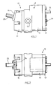
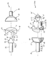
- the ball pump 10 shown in the drawing has a housing 9 composed of the housing parts 11, 12, 13 and 14, in which there is a hollow spherical working space 15, the wall 65 of which, with the exception of a narrow end face of a bearing bush 33, is spherical and has openings for it Drive shaft 25, the actuating shaft 26 and two fluid openings 43, 44 for the respective fluid to be pumped.
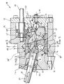
- This working space 15 is formed by the housing part 13, a sleeve 16 rotatably supported in the central part 11 of the housing and a bearing part 19 rotatably supported in a conical recess 18 of the right-hand end wall 17 of the sleeve 16 in FIG. 3.
- the parts 13, 16 and 19 are sealed against one another by sealing rings, and likewise the sleeve 16 on both sides of channels 51 and 52 relative to the housing part 11.
- a swash plate 21 and also on other parts to be sealed the passage of fluid sealant may be arranged.
- the end wall 20 of the sleeve 16 on the left-hand side in FIG. 3 has a conical recess 18 'which is rotatably mounted on a conical shoulder of the housing part 13 about the longitudinal axis 30 of the housing 9 which passes through the center 27 of the working space 15, so that the sleeve 16 is rotatably supported on the parts 13 and 19 without play and is rotatably supported about the longitudinal axis 30.
- the housing parts 11, 12, 13 and 14 are firmly connected to one another to form the rigid housing 9.
- a universal joint 24 formed from the swash plate 21, a first wedge-shaped partition wall 22 and a second wedge-shaped partition wall 23 is rotatably supported with a low plain bearing play.
- the partitions 22, 23 have the same shape.
- Their outer surfaces opposite the wall 65 of the work space as well as the circumferential surface of the swash plate 21 are sections of spherical surfaces, with the exception of the flat area of the partition wall opposite an annular shoulder 69, whose constant radii of the same size, starting from the center 27 of the work space 15, with a small plain bearing clearance allow the difference constant radii of the wall 65 starting from this center point 27 almost correspond.
- the two side walls 66, 67 of the dividing walls 22, 23 are flat and are connected at the narrow wedge ends by a straight channel 57, 58 with constant circular cross-sections, that of the form-fitting pivot slide bearing the dividing walls 22, 23 serve on straight ribs 39, 40 on both broad sides of the swash plate 21.
- the partition walls 22, 23 do not perform the pivoting movements on the ribs 39, 40 with respect to the housing 9 with a constant position of an actuating shaft 46, since they only rotate about the longitudinal axes 31, 32 of a drive shaft 25 and of a bearing journal 26 rotate and only causes the wobble movements that occur during the rotation of the swash plate 21 due to its swiveling between the swash plate 21 and the partition walls 22, 23, as long as the pump delivery rate does not set to zero on the actuating shaft 46 and in which the partition walls 22, 23 remain constant in their central positions stay on the ribs 39.40.
- the drive shaft 25 of this ball pump 10 which can be driven, for example, by means of an electric motor, is fixed.
- the journal 26 is fixed.
- the longitudinal axes 31 and 32 of this drive shaft 25 and the bearing journal 26 constantly intersect at the center 27 of the working space 15 and are inclined to one another in the position according to FIG. 3 at an obtuse angle of approximately 150 ° in this exemplary embodiment.
- the longitudinal axis 31 is immutable relative to the housing 9.
- the longitudinal axis 32 can be adjusted by rotating the bearing part 19 in its position relative to the housing 9 on a geometric conical surface, such that the angle between the geometric longitudinal axes 31 and 32 in this embodiment is adjustable between approximately 150 ° and 180 °.
- the swash plate 21 then performs wobbling movements when this angle is less than 180 °. These tumbling movements cause volume changes in the chamber 53-56 located on both sides of the partition walls, which also become smaller as the angle between the longitudinal axes becomes smaller.
- the bearing pin 26 is rotatably supported in a circular cylindrical blind bore 29 of the solid, with the exception of an external toothing 61, rotationally symmetrical bearing part 19.
- the bearing part 19 is in a conical recess in the one end wall 17 of the sleeve 16 in a form-fitting and rotatable manner about the longitudinal axis 30 of the housing 11.
- the longitudinal axes 31 and 32 of the drive shaft 25 and the bearing journal 26 enclose equally large angles of approximately 15 ° in this exemplary embodiment.
- the drive shaft 25 is rotatably supported in the slide bearing bush 33 inserted into the housing part 13 and this is sealed to the outside by an annular seal 34.
- the housing part 14 closes the recess in the housing part 13 for the bearing bush 33 and the ring seal 34 to the outside.
- the bearing part 19 is also rotatably supported on its right-hand end in relation to FIG. 3 by means of a ball 35 inserted into a bore in the housing part 12, which by means of an adjusting screw 36 forming an abutment for it in a conical bore of the bearing part 19 with little force or with little Game intervenes. This can the bearing part 19 and the sleeve 16 do not move axially.
- the two ribs 39, 40 extend over the relevant end face of the swash plate 21 and have circular cross-sections, the radii of curvature of which are constant with respect to a geometric diameter line 41 and 42 of the swash plate 21.
- These geometric diameter lines 41, 42 intersect perpendicularly in the center 27 of the working space 15 and each form a pivot axis 41, 42 for the partitions 22, 23.
- the axes of rotation 31, 32 are perpendicular to these pivot axes 41, 42.
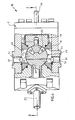
- two slit-shaped fluid openings 43 and 44 are arranged, one of which forms the inlet opening for the fluid to be conveyed into the working space 15 and the other forms the outlet opening for this fluid from the working space.
- one or the other of these openings 43 or 44 is the inlet opening and the other 44 or 43 is the outlet opening for the fluid to be conveyed.
- These fluid openings 43, 44 are arranged approximately diametrically with respect to one another with respect to this sleeve 16 and their longitudinal extensions run approximately parallel to the axis of rotation 30 of the bearing part 19.
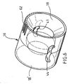
- These two fluid openings 43 and 44 are also in relation to a geometrical diameter plane of the sleeve 16, into which the Longitudinal axis 30 falls and thus also passes through the center 27 of the working space 15, each formed in mirror image to one another, as can be seen particularly clearly from FIGS. 3 and 6.
- Each The mouths of these openings 43 and 44 on the working space extend in this exemplary embodiment over approximately 50 ° central angle of the working space 15 and have the shape of a "flat three".
- these fluid openings 43, 44 have constant cross sections over their axial lengths, but it can also be provided that only partial areas of their axial lengths on the working space side have the cross sections shown and then merge into other, preferably circular cross sections.
- the sleeve 16 and the bearing part 19 are on Housing 9 can be rotated in the same direction of rotation, the respective angle of rotation of the sleeve 16 being half the angle of rotation of the bearing part 19.
- gear 45 which has an actuating shaft 46 which is rotatably mounted in the end wall 12 of the housing 11 about an axis of rotation parallel to the axis of rotation 30 of the sleeve 16, the left-hand end region of which is additionally in a bore of the middle housing part 11 is rotatably supported.
- Two gear wheels 47 and 48 are fixedly arranged on this actuating shaft 46, which is guided out of the housing 9 and can be adjusted manually or, if desired, by a motor.
- the gear 47 meshes with a toothing 62 which is arranged on the periphery of the sleeve 16 at its one end region and extends over a little more than 90 °.
- the gear 48 meshes with the toothing 61 arranged on the circumferential side on the bearing part 19, which in this exemplary embodiment is at least somewhat extends more than 180 °.
- the gears 47 and 48 are such that when the bearing part 19 is rotated by an angle a by rotating the adjusting shaft 46, then the gear 47 rotates the sleeve 16 in the same direction of rotation by the angle a / 2.
- two through bores 49 and 50 are arranged on the outer circumference for guiding the fluids to be conveyed, to which, for example, nipples (not shown) can be connected for connecting conveying lines for the fluid to be conveyed.
- nipples not shown
- Each of these openings 49, 50 opens into a channel 51, 52 of the housing part 11 that extends in the circumferential direction of the housing part 11 over a little more than 90 ° and is open toward the sleeve 16 and is semicircular in cross section.
- These two channels 51, 52 are arranged such that the one fluid opening 43 of the sleeve 16 opens at each adjustable angular position of the sleeve 16 in the one channel 51 and the other fluid opening 44 in the other channel 52, so that the fluid to be conveyed in each case from the opening 49 of the housing to the opening 50 or can be conveyed through the working space 15 from the opening 50 to the opening 49 depending on the direction of rotation of the drive shaft 25.
- the volume flows of the delivered fluid which are present at any constant rotational speed of the drive shaft 25 and thus of the universal joint 24, can be continuously adjusted between maximum and minimum, in this exemplary embodiment from the respective maximum to practically zero.
- particularly favorable characteristic curves "volume flow of the fluid to be pumped as a function of the angle setting of the bearing part 19" result in the entire angle adjustment range of approximately 180 ° of the bearing part 19. It is also possible to achieve high delivery pressures, low levels of efficiency for all delivery rates and unusually high delivery rates.
- the two partition walls 22, 23 divide the working space 15 into a total of four volume-variable chambers 53 to 56, the volume changes of which promote the respective fluid.
- the swash plate 21 has on each broad side a recess 37 and 38 with flat side walls 63 and 64, in the bottom of which the ribs 39 and the rib 40 are arranged, as can be seen particularly clearly from FIGS. 7 and 8.
- the side walls 63 are arranged in a mirror image to one another in relation to a geometric plane falling in the longitudinal axis of the rib 39 and bisecting it, as FIG. 7 shows.
- the partition wall 22 is then in the recess 37 in its central position and the partition 23 in its one limit position, in which its one flat side wall 67 practically abuts the relevant flat side wall 64 of the recess 38.
- the swash plate 24 is then adjusted so that after 90 ° the partition 22 practically rests on the other side wall 63 of the recess 37 in relation to FIG. 3, and the other partition 23 is located in it assigned recess 38 again in the central position.
- the partition 22 When turning further of the universal joint, the partition 22 then returns to its central position in the recess 37 after 90 °, and the partition 23 with its other flat side 67 practically rests on the other flat side 64 of the recess 38 of the swash plate. After a further 90 ° rotation of the universal joint 24, the universal joint 24 then made a full rotation and again reached the position according to FIG. 3. This is repeated with every full rotation of the universal joint 24 and the fluid is thus continuously conveyed through the working space 15 in the same conveying direction, very high conveying capacities and also high conveying pressures being achievable.
- the bearing part 19 is rotated by 180 ° from the position shown in FIGS. 3 and 4 for the maximum volume flow of the fluid to be conveyed at the respective speed of the drive shaft 25, the volume flow becomes practically zero and in between the volume flow changes conveyed fluids continuously as a function of the angular position of the actuating shaft 46.
- the longitudinal axis 32 of the bearing journal 26 is in alignment with the longitudinal axis 31 of the drive shaft 25 and both partition walls 22 and 23 are then constantly in the rotation of the universal joint in their middle positions, so that the two chambers 53 to 56 of the working space 15 located on both sides of each partition do not adjust their volume during the rotation of the universal joint 24 and no promotion occurs.
- the two chambers 53, 54 and 55, 56 located on both sides of each partition wall 22 and 23 change their volume during the rotation of the universal joint 24, in such a way that two of these chambers 53, 54 opposite each other one of the fluid openings 43 or, when the direction of rotation of the universal joint changes compared to the fluid opening 44 of the sleeve 16, increase their volume and thus draw in fluid from the relevant fluid opening and the other two chambers 55, 56 reduce their volume compared to the other fluid opening 44 of the sleeve 16, or if the change occurs
- Direction of rotation of the universal joint 24 increase their volume and thus press the fluid into this fluid opening 44 or suck it out of it.
- angles of rotation of the sleeve 16 and the bearing part 19 are limited to 90 ° or 180 ° by stops or their teeth 61, 62. However, they can be limited smaller if so desired.
- All parts of this ball pump 10, with the exception of the seals, can expediently be metallic or, if appropriate, in whole or in part also of other suitable materials, such as, for example, plastic, ceramic or the like.
- This ball pump 10 has numerous advantages. Your displacer formed by the universal joint 24 can rotate at a constant speed, very high speeds being achievable. It also results in high delivery rates even with a small design. It is structurally simple and composed of relatively few, inexpensive parts.
- the two partitions 22 and 23 need at least in many Cases not to be articulated to the swash plate 21, but can preferably, as in the exemplary embodiment, only be positively attached to the swash plate 21 and prevented from lifting off the swash plate 21 by the wall 65 of the working space 15 or the drive shaft 25 or the bearing pin 26 .
- the partition walls 22, 23 determine the rotating wobble movements of the swash plate 21, by means of which the changes in volume of the four chambers 53 to 56 for conveying the respective fluid are determined.
- Fluids that can be conveyed by this ball pump 10 can be gaseous fluids or liquids with a greater or lesser viscosity or liquids permeated with solids. In both cases, high delivery rates are achieved because the fluids in the spherical space are displaced in direct current.
- the two fluid openings 43 and 44 of the sleeve 16, of which only the fluid opening 43 can be seen in FIG. 3, are expediently arranged in a mirror image to one another in this exemplary embodiment in such a way that when the universal joint 24 is set to maximum conveying capacity, as is the case FIGS. 3 and 4 show that the plane of symmetry defined by the image plane and thus the geometric plane defined by the longitudinal axes 31 and 32 of the drive shaft 25 and the bearing journal 26 in this limit position of the actuating shaft 46 is their plane of symmetry.
- the slots (fluid openings) 43 and 44 of the sleeve 16 each have the shape of a flat three and their areas forming the three projections of the "three" are in the setting of the sleeve 16 shown in FIG. 3 from the perpendicular to the image plane through the longitudinal axis 30 of the housing 9 going geometric plane, which passes through the fluid openings 43 and 44 at a short distance below their centers, directed away.
Landscapes
- Engineering & Computer Science (AREA)
- Mechanical Engineering (AREA)
- General Engineering & Computer Science (AREA)
- Reciprocating Pumps (AREA)
- External Artificial Organs (AREA)
Priority Applications (1)
| Application Number | Priority Date | Filing Date | Title |
|---|---|---|---|
| AT91109463T ATE94618T1 (de) | 1990-06-25 | 1991-06-10 | Kugelpumpe. |
Applications Claiming Priority (2)
| Application Number | Priority Date | Filing Date | Title |
|---|---|---|---|
| DE4020134A DE4020134A1 (de) | 1990-06-25 | 1990-06-25 | Kugelpumpe |
| DE4020134 | 1990-06-25 |
Publications (2)
| Publication Number | Publication Date |
|---|---|
| EP0465846A1 EP0465846A1 (de) | 1992-01-15 |
| EP0465846B1 true EP0465846B1 (de) | 1993-09-15 |
Family
ID=6408999
Family Applications (1)
| Application Number | Title | Priority Date | Filing Date |
|---|---|---|---|
| EP91109463A Expired - Lifetime EP0465846B1 (de) | 1990-06-25 | 1991-06-10 | Kugelpumpe |
Country Status (4)
| Country | Link |
|---|---|
| EP (1) | EP0465846B1 (cg-RX-API-DMAC10.html) |
| AT (1) | ATE94618T1 (cg-RX-API-DMAC10.html) |
| DD (1) | DD296736A5 (cg-RX-API-DMAC10.html) |
| DE (2) | DE4020134A1 (cg-RX-API-DMAC10.html) |
Families Citing this family (7)
| Publication number | Priority date | Publication date | Assignee | Title |
|---|---|---|---|---|
| US6241493B1 (en) * | 1999-08-17 | 2001-06-05 | Spherical Machines, Inc. | Spherical fluid machine with control mechanism |
| US7214045B2 (en) * | 1999-08-17 | 2007-05-08 | Spherical Machines, Inc. | Spherical fluid machine with flow control mechanism |
| CN105782022B (zh) * | 2016-04-26 | 2017-12-15 | 无锡博泰微流体技术有限公司 | 球形泵冷却机构 |
| CN105756933B (zh) * | 2016-04-26 | 2017-10-10 | 无锡博泰微流体技术有限公司 | 一种球形压缩机齿轮过死点机构 |
| CN106014973B (zh) * | 2016-07-25 | 2018-08-17 | 华中科技大学 | 一种具有间歇冷却功能的球形泵 |
| PL448938A1 (pl) * | 2024-06-22 | 2025-03-17 | Henryk Sobczuk | Maszyna rotacyjna |
| PL448977A1 (pl) * | 2024-06-26 | 2025-03-31 | Henryk Sobczuk | Maszyna rotacyjna |
Family Cites Families (8)
| Publication number | Priority date | Publication date | Assignee | Title |
|---|---|---|---|---|
| DE808915C (de) * | 1949-05-17 | 1951-07-19 | Heinrich Gerken | Kugelkolbenpumpe |
| US2678003A (en) * | 1950-07-14 | 1954-05-11 | Gerken Heinrich | Ball piston pump |
| DE842006C (de) * | 1950-07-15 | 1952-06-23 | Heinrich Gerken | Kugelkolbenpumpe mit verstellbarer Blindwelle |
| DE954027C (de) * | 1953-01-30 | 1956-12-13 | Wilhelm Fette Praez Swerkzeug | Kugelkolbenpumpe |
| DE1010834B (de) * | 1954-05-13 | 1957-06-19 | Malte Roennbom | Kugelkolbenpumpe |
| DE1553165A1 (de) * | 1965-11-19 | 1970-07-30 | Poetes Wilhelm Josef | Kugelmotor (Kugelpumpe) mit Kreuzgelenk-Drehkolben |
| US3549286A (en) * | 1967-06-22 | 1970-12-22 | Maurice J Moriarty | Rotary engine |
| US3816039A (en) * | 1971-08-02 | 1974-06-11 | Commercial Metals Co | Rotary air pump with rotating and oscillating center piston |
-
1990
- 1990-06-25 DE DE4020134A patent/DE4020134A1/de active Granted
- 1990-07-20 DD DD90342953A patent/DD296736A5/de not_active IP Right Cessation
-
1991
- 1991-06-10 DE DE91109463T patent/DE59100378D1/de not_active Expired - Fee Related
- 1991-06-10 AT AT91109463T patent/ATE94618T1/de not_active IP Right Cessation
- 1991-06-10 EP EP91109463A patent/EP0465846B1/de not_active Expired - Lifetime
Also Published As
| Publication number | Publication date |
|---|---|
| DE59100378D1 (de) | 1993-10-21 |
| EP0465846A1 (de) | 1992-01-15 |
| ATE94618T1 (de) | 1993-10-15 |
| DD296736A5 (de) | 1991-12-12 |
| DE4020134C2 (cg-RX-API-DMAC10.html) | 1992-09-17 |
| DE4020134A1 (de) | 1992-01-09 |
Similar Documents
| Publication | Publication Date | Title |
|---|---|---|
| DE69101716T2 (de) | Pumpe mit Mehrfachauslass. | |
| DE1503603C3 (de) | Regelbarer Schraubenverdichter mit einem Schraubenrippenrotor, einem Schraubennutenrotor und einem axial verstellbaren Ventilschieber | |
| EP0620898A1 (de) | Regelbare flügelzellenpumpe in kompakter bauweise. | |
| DE2526175A1 (de) | Einrichtung zum veraendern der volumetrischen kapazitaet eines parallel- und aussenachsigen rotationskolbenverdichters mit kaemmeingriff | |
| EP0044070A1 (de) | Axialkolbenpumpe für zwei Förderströme | |
| DE3247376A1 (de) | Durchflussmengenzaehler fuer fluessigkeiten | |
| EP0465846B1 (de) | Kugelpumpe | |
| DE2448594B2 (de) | Axialkolbenmaschine | |
| DE2115350C3 (de) | Einrichtung zur Geräuschminderung an einer schlitzgesteuerten Axialkolbenpumpe | |
| EP0697520B1 (de) | Kugelkopf zur Abstützung eines Kolbens einer hydrostatischen Axial- oder radialkolbenmaschine an deren Hubkörper | |
| EP0242579B1 (de) | Vorrichtung zur Regelung der Menge und/oder des Mischungsverhältnisses eines Brenngas-Luft-Gemisches | |
| DE10207350C5 (de) | Volumenstromvariable Rotorpumpe | |
| DE2634318A1 (de) | Pumpe, vorzugsweise zum dosieren und kalibrieren | |
| DE19623242C1 (de) | Sperrflügelpumpe | |
| DE3418708A1 (de) | Pumpe | |
| EP0929743B1 (de) | Radialkolbenpumpe | |
| DE3127610A1 (de) | Axialkolbenpumpe fuer zwei foerderstroeme | |
| DE2038086B2 (de) | Axialkolbenmaschine | |
| DE19616125C2 (de) | Kugelkolbenpumpe | |
| DE2911655A1 (de) | Rollkolbenpumpe | |
| DE19914266C2 (de) | Axialkolbenmaschine und Steuerkörper für eine Axialkolbenmaschine | |
| DE4312498C2 (de) | Förderpumpe | |
| WO2004046554A1 (de) | Innenzahnradpumpe | |
| DE10007072B4 (de) | Mehrwegeventil und System mit einem derartigen Mehrwegeventil | |
| DE1403942C (de) | Einlaß- und Auslaßanordnung bei einer ventillosen Rotationskolbenpumpe für gleichbleibende Forderrichtung |
Legal Events
| Date | Code | Title | Description |
|---|---|---|---|
| PUAI | Public reference made under article 153(3) epc to a published international application that has entered the european phase |
Free format text: ORIGINAL CODE: 0009012 |
|
| AK | Designated contracting states |
Kind code of ref document: A1 Designated state(s): AT BE CH DE DK ES FR GB IT LI NL SE |
|
| 17P | Request for examination filed |
Effective date: 19911202 |
|
| 17Q | First examination report despatched |
Effective date: 19920621 |
|
| GRAA | (expected) grant |
Free format text: ORIGINAL CODE: 0009210 |
|
| AK | Designated contracting states |
Kind code of ref document: B1 Designated state(s): AT BE CH DE DK ES FR GB IT LI NL SE |
|
| PG25 | Lapsed in a contracting state [announced via postgrant information from national office to epo] |
Ref country code: IT Free format text: LAPSE BECAUSE OF FAILURE TO SUBMIT A TRANSLATION OF THE DESCRIPTION OR TO PAY THE FEE WITHIN THE PRE;WARNING: LAPSES OF ITALIAN PATENTS WITH EFFECTIVE DATE BEFORE 2007 MAY HAVE OCCURRED AT ANY TIME BEFORE 2007. THE CORRECT EFFECTIVE DATE MAY BE DIFFERENT FROM THE ONE RECORDED.SCRIBED TIME-LIMIT Effective date: 19930915 Ref country code: NL Effective date: 19930915 Ref country code: SE Effective date: 19930915 Ref country code: ES Free format text: THE PATENT HAS BEEN ANNULLED BY A DECISION OF A NATIONAL AUTHORITY Effective date: 19930915 Ref country code: FR Effective date: 19930915 Ref country code: GB Effective date: 19930915 Ref country code: DK Effective date: 19930915 Ref country code: BE Effective date: 19930915 |
|
| REF | Corresponds to: |
Ref document number: 94618 Country of ref document: AT Date of ref document: 19931015 Kind code of ref document: T |
|
| REF | Corresponds to: |
Ref document number: 59100378 Country of ref document: DE Date of ref document: 19931021 |
|
| EN | Fr: translation not filed | ||
| NLV1 | Nl: lapsed or annulled due to failure to fulfill the requirements of art. 29p and 29m of the patents act | ||
| GBV | Gb: ep patent (uk) treated as always having been void in accordance with gb section 77(7)/1977 [no translation filed] |
Effective date: 19930915 |
|
| PG25 | Lapsed in a contracting state [announced via postgrant information from national office to epo] |
Ref country code: AT Effective date: 19940610 |
|
| PG25 | Lapsed in a contracting state [announced via postgrant information from national office to epo] |
Ref country code: LI Effective date: 19940630 Ref country code: CH Effective date: 19940630 |
|
| PLBE | No opposition filed within time limit |
Free format text: ORIGINAL CODE: 0009261 |
|
| 26N | No opposition filed | ||
| REG | Reference to a national code |
Ref country code: CH Ref legal event code: PL |
|
| PGFP | Annual fee paid to national office [announced via postgrant information from national office to epo] |
Ref country code: DE Payment date: 19990107 Year of fee payment: 8 |
|
| PG25 | Lapsed in a contracting state [announced via postgrant information from national office to epo] |
Ref country code: DE Free format text: LAPSE BECAUSE OF NON-PAYMENT OF DUE FEES Effective date: 20000503 |