EP0464385A1 - Steckverbinder - Google Patents
Steckverbinder Download PDFInfo
- Publication number
- EP0464385A1 EP0464385A1 EP91109176A EP91109176A EP0464385A1 EP 0464385 A1 EP0464385 A1 EP 0464385A1 EP 91109176 A EP91109176 A EP 91109176A EP 91109176 A EP91109176 A EP 91109176A EP 0464385 A1 EP0464385 A1 EP 0464385A1
- Authority
- EP
- European Patent Office
- Prior art keywords
- guide
- connector
- conductor wires
- plug
- housing part
- Prior art date
- Legal status (The legal status is an assumption and is not a legal conclusion. Google has not performed a legal analysis and makes no representation as to the accuracy of the status listed.)
- Ceased
Links
- 239000004020 conductor Substances 0.000 claims abstract description 72
- 230000013011 mating Effects 0.000 claims abstract description 3
- 230000007704 transition Effects 0.000 claims 1
- 238000003780 insertion Methods 0.000 description 6
- 230000037431 insertion Effects 0.000 description 6
- 238000005516 engineering process Methods 0.000 description 2
- 238000004519 manufacturing process Methods 0.000 description 2
- 238000005452 bending Methods 0.000 description 1
- 230000008878 coupling Effects 0.000 description 1
- 238000010168 coupling process Methods 0.000 description 1
- 238000005859 coupling reaction Methods 0.000 description 1
- 238000002347 injection Methods 0.000 description 1
- 239000007924 injection Substances 0.000 description 1
- 238000007493 shaping process Methods 0.000 description 1
Images
Classifications
-
- H—ELECTRICITY
- H01—ELECTRIC ELEMENTS
- H01R—ELECTRICALLY-CONDUCTIVE CONNECTIONS; STRUCTURAL ASSOCIATIONS OF A PLURALITY OF MUTUALLY-INSULATED ELECTRICAL CONNECTING ELEMENTS; COUPLING DEVICES; CURRENT COLLECTORS
- H01R12/00—Structural associations of a plurality of mutually-insulated electrical connecting elements, specially adapted for printed circuits, e.g. printed circuit boards [PCB], flat or ribbon cables, or like generally planar structures, e.g. terminal strips, terminal blocks; Coupling devices specially adapted for printed circuits, flat or ribbon cables, or like generally planar structures; Terminals specially adapted for contact with, or insertion into, printed circuits, flat or ribbon cables, or like generally planar structures
- H01R12/70—Coupling devices
- H01R12/71—Coupling devices for rigid printing circuits or like structures
- H01R12/712—Coupling devices for rigid printing circuits or like structures co-operating with the surface of the printed circuit or with a coupling device exclusively provided on the surface of the printed circuit
- H01R12/716—Coupling device provided on the PCB
-
- H—ELECTRICITY
- H01—ELECTRIC ELEMENTS
- H01R—ELECTRICALLY-CONDUCTIVE CONNECTIONS; STRUCTURAL ASSOCIATIONS OF A PLURALITY OF MUTUALLY-INSULATED ELECTRICAL CONNECTING ELEMENTS; COUPLING DEVICES; CURRENT COLLECTORS
- H01R13/00—Details of coupling devices of the kinds covered by groups H01R12/70 or H01R24/00 - H01R33/00
- H01R13/46—Bases; Cases
- H01R13/502—Bases; Cases composed of different pieces
- H01R13/506—Bases; Cases composed of different pieces assembled by snap action of the parts
-
- H—ELECTRICITY
- H01—ELECTRIC ELEMENTS
- H01R—ELECTRICALLY-CONDUCTIVE CONNECTIONS; STRUCTURAL ASSOCIATIONS OF A PLURALITY OF MUTUALLY-INSULATED ELECTRICAL CONNECTING ELEMENTS; COUPLING DEVICES; CURRENT COLLECTORS
- H01R13/00—Details of coupling devices of the kinds covered by groups H01R12/70 or H01R24/00 - H01R33/00
- H01R13/64—Means for preventing incorrect coupling
Definitions
- the invention relates to a connector according to the preamble of claim 1.
- Connectors are known in practice, in which the electrical connections or conductor wires of the contact elements are contacted on printed circuit boards.
- the ends of the connections or the electrical conductor wires are either plugged into contact bores and then soldered or, in the case of the so-called SMD (surface mounted devices) technology, soldered flat onto the conductor tracks.
- the connection ends of the conductor wires generally have a different arrangement and / or orientation than the contact elements in the connector. Because of the small interconnect spacing, the connection ends must be aligned very precisely to one another and to the fastening means arranged on the plug housing. This requirement is particularly difficult to meet with connectors whose ends are bent transversely to the direction of insertion.
- Plug connectors are therefore known in which the contact elements are cast in the plug body up to their actual connection ends, that is to say, for example, beyond their break points, so that only the connection ends of the contact elements or the electrical conductors protrude from the plug body.
- the contact connections have to be bent with high precision and then inserted into the plastic injection mold for the connector body. Such a production requires a high amount of tools and therefore costs.
- the invention has for its object to provide a connector of the type mentioned, in which the alignment of the connection ends of the electrical conductor wires is possible without separate shaping tools.
- the guide part is advantageously arranged and designed in such a way that the electrical conductor wires are deflected when the plug connector is assembled. This ensures that no additional tools and no additional time are required for the deflection of the electrical conductors, but this deflection takes place automatically at the same time as the connector is being installed.
- the guide part By mounting the guide part on the plug core, the conductor wires emerging from it are caught by the guide channels and deflected so that the exit-side arrangement pattern corresponds to the desired arrangement.
- a frequently existing task is to fan out the conductor wires of a circular plug with contact elements arranged in a circle, so that the conductor wires lie side by side in straight or curved rows.
- the measure according to claim 4 serves this purpose.
- the guide channels connecting the passage openings to one another thus enable the electrical conductors to be fanned out, which are arranged in a circle on the side facing the plug core and are first deflected by means of the channels parallel to the plug-in direction in such a way that the electrical conductors essentially next to one another transversely to the plug-in direction, i.e. also no longer lie partially on top of each other.
- the measures described above are preferably used to deflect the conductor wires so that they have a different arrangement pattern at the exit of the guide part than at the entrance thereof, the orientation of the conductor wires preferably remaining unchanged.
- the task is often to bend the conductor wires so that the connector has, for example, contact elements aligned parallel to the circuit board, but the conductor wire ends are perpendicular to the circuit board.
- the measures of claim 6 are provided according to the invention.
- each electrical conductor is gripped by the guide groove assigned to it and deflected transversely to the direction of insertion.
- the individual electrical conductors are therefore, for example, side by side in a plane transverse to the direction of insertion.
- the mutual distance between the individual electrical conductors is determined by the distance between them the passage openings located away from the plug core and by the mutual spacing of the guide grooves.
- the guide grooves preferably begin at least at the level of the passage openings on the side of the connector holder facing away from the connector core and end on the side to which the ends of the electrical conductors are deflected.
- the guide grooves are only located at the points to which the electrical conductors can also reach.
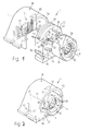
- FIG. 1 An embodiment of the connector 1 is shown schematically in Figures 1 and 2.
- the plug core 4 has an approximately cylindrical cross section, the contact elements 30 projecting approximately circularly in the axial direction from the plug core 4.
- a fastening sleeve 29 is adapted to the cross-section of the plug core 4, completely surrounds it and projects beyond the front, free ends of the contact elements 30 seated on the plug core 4 in the axial direction by a small amount.
- the fastening sleeve 29 has a guide groove 31 cut into its cylindrical outer surface for receiving a mating connector (not shown in more detail).
- a guide part 32 is provided in the axial direction behind the plug core 4, which has passage openings 33 for the electrical conductors 34 (only one electrical conductor is indicated in FIGS. 1 and 2) and latching elements 35, which with counter-latching elements of the fastening sleeve 29, not shown or the plug core 4 cooperate to connect these parts with the guide part 32.
- the number of through openings 33 corresponds at least to the number of contact elements 30.
- the connector 1 has a hood-shaped housing part 36 with a front opening 37 and a transverse inner wall 40, which is provided with guide grooves 41 running transverse to the direction of insertion.
- the housing part 36 can be pushed onto the plug holder 32 transversely to the direction of insertion, from top to bottom in FIG. 1, the individual electrical conductors 34 being deflected downward in FIG. 1 by means of the guide groove 41 assigned to each conductor 34.
- the passage openings 33 are connected to each other via a channel 44 on the side 42, 43 of the plug holder 32 facing and facing away from the plug core 4 and are arranged on the side 43 of the guide part 32 facing away from the plug core 4 such that all conductors 34 leaving these passage openings lie side by side.
- the channels assigned to each passage opening 33 can each run mainly horizontally and only provide lateral guidance of the individual electrical conductors. However, it is also possible to provide the channels inclined in the guide part 32 and thereby additionally to influence the respective height of the end 45 of the electrical conductor 34 projecting beyond the side 43.
- the guide grooves 41 begin in the assembled state of the connector 1 according to FIGS. 1 and 2 at the level of the through openings on the side 43 of the guide part 32 facing away from the plug core 4 and end on the side to which the ends 45 of the electrical conductors 34 are deflected.
- the electrical conductors 34 are bent over to the underside 46 of the guide part 32, so that a first upper kink 47 is formed in at least part of the electrical conductors 34 (see FIG. 2).
- the through openings 33 on the side 42 of the guide part 32 facing the plug core 4 are partly circular, partly as an elongated hole running transversely to the plug direction, the cross-sectional area of the through openings 33 extending from the underside 46 of the guide part 32 to its upper side 50 increases.
- the passage opening 33 closest to the underside 46 is circular and the passage openings adjoining it to the upper side 50 are designed as an elongated hole of increasing length.
- the radially inner ends of the individual passage openings 33 lie approximately on a circular arc around the longitudinal axis 51, the radius of which corresponds to the distance of the individual contact elements 30 or electrical conductors 34 from the longitudinal axis 51. This ensures that when the plug core 4 or the fastening sleeve 29 is clipped onto the guide part 32, each electrical conductor 34 is inserted into one of the through openings 33 and is guided along each channel 44 adjoining it.
- the openings are arranged approximately in a V-shape, the individual ends 45 of the electrical conductors 34 being adjacent to one another, ie the individual ends 45 of the electrical conductors 34 are on the side 43 of the plug holder 32 at different distances from one another Bottom 46, ie with different heights, but not partially or completely arranged one above the other. It is of course also possible to provide the passage openings 33 on the side 43 other than V-shaped, for example semicircular, as long as the above condition is fulfilled.
- the hood-shaped housing part 36 can be latched on the guide part 32 by means of a latching projection 52 provided in pairs, in that the latching projection 52 engages in a correspondingly designed latching recess 53 which is formed near the underside 46.
- the locking projection and recess are shown in FIG. 1 only on one side of the housing part 36 and the guide part 32, but are provided in pairs.
- a triangular marking 55 is attached near the front edge 54 of the housing part 36, which indicates the different positions of a coupling part, not shown, connected to the connector 1, with a corresponding marking.
- the mounting sleeve 29 is inserted axially projecting into the housing part 36, so that this connector forms a body socket.
- this connector forms a body socket.
- a coding 56 is provided on the upper side of the plug core 4 according to FIGS. 1 and 2. However, it is also possible to manufacture the connector without such coding.
- Figure 1 also shows that the guide groove 41 is near its respective lower end parallel to the direction of insertion, i.e. to the rear in FIG. 1, that is, to the side of the inner wall 40 facing away from the guide part 32.
- This makes it possible, as indicated in FIG. 2, to bend each electrical conductor 34 horizontally near the underside 46 of the plug holder 32, so that each conductor has a lower bend 57 in addition to the upper bend 47.
- the plug is then suitable for mounting using the SMD technology mentioned at the beginning.
- the respective spacings of the electrical conductors are determined by the spacings of the through openings 33 in the side 43 of the plug holder 32 and by the respective mutual spacings of the guide grooves 41.
- the fastening sleeve 29 is first pushed onto the plug core 4 equipped with contact elements 30 and fastened to it in a manner not shown.
- the individual electrical conductors 34 are connected to the contact elements 30 and project in the axial direction via the fastening sleeve 29.
- the fastening sleeve with the plug core is then guided along the longitudinal axis 51 to the guide part 32 in such a way that the individual electrical conductors 34 are inserted into the passage openings 33 and can extend along the channels 44 located behind them.
- the fastening sleeve and plug core are guided closer to the guide part 32, the ends 45 of the electrical conductors 34 emerge on the side 43 of the guide part 32 facing away from the plug core, wherein finally a fastening sleeve and / or plug core can be locked in place with the guide part 32 by means of the latching elements 35 is.
- the mounting sleeve and connector core are thus firmly attached to the connector holder.
- the housing part 36 Passing the electrical conductors through the channels 44 enables the conductors to be fanned out, so that when the housing part 36 is pushed on, they are deflected downward onto the guide part 32 according to FIG. 2.
- the housing part 36 finally latches on the guide part 32 by means of a latching projection 52 and latching recess 53. After the ends 45 have been deflected horizontally, they lie next to one another in a horizontal plane in the region of the horizontally extending guide slots 41.
- the electrical conductors of the connector can thus easily be e.g. be connected to a circuit board.
Landscapes
- Coupling Device And Connection With Printed Circuit (AREA)
- Details Of Connecting Devices For Male And Female Coupling (AREA)
Applications Claiming Priority (2)
| Application Number | Priority Date | Filing Date | Title |
|---|---|---|---|
| DE19904018033 DE4018033A1 (de) | 1990-06-05 | 1990-06-05 | Steckverbinder fuer ein ein- oder mehradriges kabel |
| DE4018033 | 1990-06-05 |
Publications (1)
| Publication Number | Publication Date |
|---|---|
| EP0464385A1 true EP0464385A1 (de) | 1992-01-08 |
Family
ID=6407835
Family Applications (1)
| Application Number | Title | Priority Date | Filing Date |
|---|---|---|---|
| EP91109176A Ceased EP0464385A1 (de) | 1990-06-05 | 1991-06-05 | Steckverbinder |
Country Status (2)
| Country | Link |
|---|---|
| EP (1) | EP0464385A1 (enExample) |
| DE (1) | DE4018033A1 (enExample) |
Cited By (1)
| Publication number | Priority date | Publication date | Assignee | Title |
|---|---|---|---|---|
| CN1076304C (zh) * | 1995-10-31 | 2001-12-19 | 安全盖系统公司 | 瓶或类似物品的封口 |
Families Citing this family (1)
| Publication number | Priority date | Publication date | Assignee | Title |
|---|---|---|---|---|
| DE19918652C2 (de) * | 1999-04-16 | 2003-10-02 | Heidenhain Gmbh Dr Johannes | Drehbare Anschlußeinheit für eine elektrische Baueinheit |
Citations (3)
| Publication number | Priority date | Publication date | Assignee | Title |
|---|---|---|---|---|
| EP0226086A2 (en) * | 1985-12-13 | 1987-06-24 | Allied Corporation | Surface mount connector |
| EP0249441A2 (en) * | 1986-06-10 | 1987-12-16 | Positronic Industries, Inc. | Fixed connector for making electrical connections to surface-mount type printed board |
| US4735582A (en) * | 1986-11-26 | 1988-04-05 | E. I. Du Pont De Nemours And Company | Soldered cable transition connector |
Family Cites Families (3)
| Publication number | Priority date | Publication date | Assignee | Title |
|---|---|---|---|---|
| DE8702058U1 (de) * | 1987-02-11 | 1987-04-16 | Lisa Dräxlmaier GmbH, 84137 Vilsbiburg | Bordnetzstecker für Kraftfahrzeuge |
| DE3710685C1 (en) * | 1987-03-31 | 1988-10-20 | Murr Formenbau Gmbh | Right-angle (elbow, angle-entry) plug |
| DE3810886C2 (de) * | 1988-03-30 | 1997-04-30 | Draexlmaier Lisa Gmbh | Kerzenstecker, insbesondere für Glühkerzen |
-
1990
- 1990-06-05 DE DE19904018033 patent/DE4018033A1/de active Granted
-
1991
- 1991-06-05 EP EP91109176A patent/EP0464385A1/de not_active Ceased
Patent Citations (3)
| Publication number | Priority date | Publication date | Assignee | Title |
|---|---|---|---|---|
| EP0226086A2 (en) * | 1985-12-13 | 1987-06-24 | Allied Corporation | Surface mount connector |
| EP0249441A2 (en) * | 1986-06-10 | 1987-12-16 | Positronic Industries, Inc. | Fixed connector for making electrical connections to surface-mount type printed board |
| US4735582A (en) * | 1986-11-26 | 1988-04-05 | E. I. Du Pont De Nemours And Company | Soldered cable transition connector |
Cited By (1)
| Publication number | Priority date | Publication date | Assignee | Title |
|---|---|---|---|---|
| CN1076304C (zh) * | 1995-10-31 | 2001-12-19 | 安全盖系统公司 | 瓶或类似物品的封口 |
Also Published As
| Publication number | Publication date |
|---|---|
| DE4018033A1 (de) | 1991-12-12 |
| DE4018033C2 (enExample) | 1993-04-29 |
Similar Documents
| Publication | Publication Date | Title |
|---|---|---|
| DE60014719T2 (de) | Kabelverbinder mit gesteuerter impedanz | |
| DE2752117C2 (de) | Elektrisches Verbindergehäuse | |
| DE3239708C2 (enExample) | ||
| DE2414640B2 (de) | Elektrischer Verbinder mit einer metallischen Anschlußklemme | |
| EP0959529B1 (de) | Elektrische Anschlussbaueinheit | |
| EP2018684B1 (de) | Modul mit anschlüssen für aktoren und/oder sensoren | |
| DE2735838C2 (de) | Elektrische Anschlußklemme und elektrisches Kabelverbindungsglied | |
| DE4235835C2 (de) | Steckverbindung | |
| DE102016124172A1 (de) | Steckverbinder zur kraftlosen Kontaktierung auf einer Leiterkarte | |
| EP4169130B1 (de) | Modular aufbaubaren steckverbinder | |
| EP2856558B1 (de) | Rj45-stecker mit führungseinrichtung für litzen | |
| DE2406417A1 (de) | Elektrischer verbinder zur verbindung eines koaxialkabels mit einer gedruckten schaltungsplatte | |
| DE3433822C2 (enExample) | ||
| DE69319259T2 (de) | Verbesserte Kontakte für den Anschluss von Spulenwicklungen | |
| DE2714158C2 (de) | Anschlußvorrichtung für ein vieladriges Kabel | |
| EP0464385A1 (de) | Steckverbinder | |
| EP0127849B1 (de) | Relais | |
| DE2534292C2 (enExample) | ||
| DE102020104417B4 (de) | Anschlussklemme | |
| EP0388489B1 (de) | Elektrischer Steckverbinder | |
| DE2851712C2 (de) | Steckverbinder | |
| DE2915679A1 (de) | Verbinder fuer flexible kabel | |
| DE3035817C2 (de) | Halterung für Bandleitungen an gedruckten Schaltungsplatten | |
| DE4445658C2 (de) | Verfahren zur Bestückung einer Grundleiste eines Steckverbinders für eine Printplatte mit Kontaktanschlüssen | |
| EP1391967A1 (de) | Anschlussvorrichtung |
Legal Events
| Date | Code | Title | Description |
|---|---|---|---|
| PUAI | Public reference made under article 153(3) epc to a published international application that has entered the european phase |
Free format text: ORIGINAL CODE: 0009012 |
|
| AK | Designated contracting states |
Kind code of ref document: A1 Designated state(s): AT BE CH DE DK ES FR GB GR IT LI LU NL SE |
|
| RBV | Designated contracting states (corrected) |
Designated state(s): FR GB IT |
|
| REG | Reference to a national code |
Ref country code: DE Ref legal event code: 8566 |
|
| 17P | Request for examination filed |
Effective date: 19920701 |
|
| 17Q | First examination report despatched |
Effective date: 19940328 |
|
| STAA | Information on the status of an ep patent application or granted ep patent |
Free format text: STATUS: THE APPLICATION HAS BEEN REFUSED |
|
| 18R | Application refused |
Effective date: 19940924 |