EP0459342A2 - Dispositif de tri - Google Patents
Dispositif de tri Download PDFInfo
- Publication number
- EP0459342A2 EP0459342A2 EP91108564A EP91108564A EP0459342A2 EP 0459342 A2 EP0459342 A2 EP 0459342A2 EP 91108564 A EP91108564 A EP 91108564A EP 91108564 A EP91108564 A EP 91108564A EP 0459342 A2 EP0459342 A2 EP 0459342A2
- Authority
- EP
- European Patent Office
- Prior art keywords
- sorting
- central computer
- units
- control
- sorting units
- Prior art date
- Legal status (The legal status is an assumption and is not a legal conclusion. Google has not performed a legal analysis and makes no representation as to the accuracy of the status listed.)
- Withdrawn
Links
Images
Classifications
-
- B—PERFORMING OPERATIONS; TRANSPORTING
- B07—SEPARATING SOLIDS FROM SOLIDS; SORTING
- B07C—POSTAL SORTING; SORTING INDIVIDUAL ARTICLES, OR BULK MATERIAL FIT TO BE SORTED PIECE-MEAL, e.g. BY PICKING
- B07C5/00—Sorting according to a characteristic or feature of the articles or material being sorted, e.g. by control effected by devices which detect or measure such characteristic or feature; Sorting by manually actuated devices, e.g. switches
- B07C5/36—Sorting apparatus characterised by the means used for distribution
- B07C5/361—Processing or control devices therefor, e.g. escort memory
Definitions
- the invention relates to a device for sorting individual parts, e.g. glass fragments according to their color.
- a device for sorting individual parts e.g. glass fragments according to their color.
- Such a device is known from DE-OS 38 04 391.2. It is used to recycle used glass, which is usually in a mixture of differently colored glass, for economic recycling.
- the waste glass is broken up into fragments with an edge length of approximately 5 to 50 mm.
- the fragments are then guided past a color recognition unit via a U-shaped slide.
- the color recognition unit sends light through the fragment and determines the absorption of the light in the fragment. It is determined whether the fragment is colored, clear or opaque.
- the distribution of the fragments on the individual channels depending on the type of fragment takes place via floor openings in the bottom of the slide.
- the bottom openings are provided with flaps that can be actuated by electromagnets.
- the lower channels are each provided with floor openings.
- the invention has for its object to make the control for such a variety of sorting units advantageous.
- the necessary control is split up into a part that is only assigned to the individual sorting unit and a part that is only available once for the system. These parts are assigned very specific tasks. This division is possible through networking.
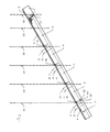
- the sorting unit in FIG. 1 is constructed from a metal angle with a leg 1 lying in the plane of the drawing and a leg 2 protruding in the direction of the viewer from the plane of the drawing.
- the leg 2 is covered with a glass plate 3 on which the fragments lie flat and from the right slide to the bottom left of the drawing.
- the slide's angle of inclination is about 30 degrees.
- the chute 1, 2 is tilted in such a way that the fragments 4 lie against the edge (38 in FIG. 2) of the leg 2 facing the leg 1 when it slides. An angle of approximately 4 degrees is sufficient. So that the leg 1 does not wear out, it is also covered with glass panes 5-9.
- 10 - 17 fragment detection sensors are provided at several locations. At positions 10, 12, 14 and 16 z. B. color detection sensors and at points 11, 13, 15 and 17 metal detection sensors are provided.
- a pulse generator 18 - 21 belongs to each of a color detection sensor and a metal detection sensor.
- the pulse transmitters are capable of applying a mechanical pulse to the fragment, which is directed in such a way that the fragment can be accelerated away from the leg 1.
- the pulse generators 18-21 are arranged so that the pulse hits the narrow break edge of the fragment. The fragment 4 is thus hit at the center of gravity. As a result, the fragment 4 is actually moved in the direction of the pulse and does not perform any uncontrollable rotary movements.
- the pulse generators 18-21 are air nozzles, which the fragment 4 slides past the air nozzle for a very short time, e.g. B. can apply 0.1 seconds with a pressure pulse. This pulse accelerates the fragment 4 perpendicular to the normal direction of movement of the fragment. It falls over the edge of the leg 2 from the slide.
- a drop chute is assigned to each pulse generator 18-21.
- the chutes are separated from one another by partitions 22 and end at the bottom on conveyors which are not shown here.
- No pulse generator is assigned to the chute on the far left in FIG. 1. Parts are conveyed here that were not considered worthy of promotion at any recognition station.
- the chute 1, 2 simply has a boundary wall 23 at its lower end. The parts that have not previously been conveyed out collide against this wall 23 and, since the parts are piled up, fall down from the slide into the chute below. This desired jamming effect on the wall 23 prevents the parts of the device from being worn out by the impact.
- green glass is sorted out, including the other glass colors that were not sorted out at the first two sorting points.
- the first three digits are each equipped with a metal detection sensor 11, 13 and 15 in order to exclude fragments that have metal residues from being sorted out. Such fragments, which still carry remnants of metal, and also individual pieces of metal should only be sorted out at the fourth pulse generator 21.
- This fourth sorting point can again be equipped with a color sensor 16 and a metal detection sensor 17. However, it is sufficient to provide only one light barrier which registers the passage of the fragment and allows the pulse generator 21 to respond at the right time. The fact that it is a fragment containing metal is already from the previous sorting point 14, 15, 20 with the metal detector 15 present there. The light barrier then only serves to precisely determine the time of ejection.
- the fifth chute e.g. made of ceramic, porcelain or stone.
- the disks 5 - 9, against which the fragments 4 abut during the slide, are arranged next to one another with an intermediate space 24.
- the gap 24 is so large that the pulse generators 18-21 fit through this slot.
- the fragments 4 could each abut the front edge of each glass sheet 5-9. Such a collision could cause the fragment 4 to move in an uncontrolled manner and hinder the sliding movement.
- the end of the glass panes 6, 7, 8, 9 is lifted by a few tenths of a millimeter from the leg 1 of the angle 1, 2, e.g. B. by placing a spacer.
- the glass panes are arranged in a scale-like manner. In each case towards the end of the glass pane, the fragment 4 is rejected somewhat more by the leg 1 than at the beginning of the pane. This prevents a collision with the front edge of the pane.
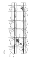
- FIG. 2 shows the same sorting device as Figure 1 in plan view. Two sorting devices are shown parallel to each other to describe a further detail of the sorting devices. The same parts contain the same reference numerals as in Figure 1.
- valve blocks 27-30 are visible, which are supplied with air via an air supply hose 31.
- the valve blocks are connected to one another by means of connecting pipes 33 for the supply of air.
- the valve blocks 27-30 contain air channels and electromagnetically actuated valves which can release the air flow to the pulse generator nozzles 18-21 mentioned in FIG.
- the valve block 30 contains an additional outlet hose 32 and an additional valve for controlling the supply of fragments to the sorting channel.
- the feed device is not described in detail here.
- Line 34 shows the path of a piece of white glass.
- the fragment is recognized as white glass on the color recognition sensor 10. It is recognized on the metal detector 11 that it is not a piece of metal and is not contaminated with residues of metal. Because these two conditions are met, the nozzle 18 is actuated at the right time and the fragment 4 is deflected along the line 34. The fragment 4 is thrown onto a plate 35, where a pile 36 of white glass fragments has already accumulated. The accumulated pile 36 of the fragments protects the plate 35 against wear from the impact. When heap 36 is piled high enough, fall the fragments in the direction of arrow 37 into the chute below. In the same way, collecting plates 35 are provided in the other chutes, but are not shown.
- Suitable sensors are connected to the computer via analog channels to determine the type of fragments and output drivers to control the valve blocks 27-30.
- the fragment is illuminated from below with a white light beam for color recognition.
- the chute 2 there are optical sensors which deliver analog intensity signals for the spectral ranges "red”, “green” and “blue”. These signals are fed to the analog channels of the single-board computer and are evaluated to control the pulse generators 18-21. The glass color is used to determine the relationship between the signals.
- metal detection sensors 11, 13, 15 and 17 which use the eddy current loss of a coil fed with alternating current for detection.
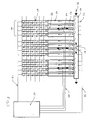
- FIG. 3 shows a sorting device in which a multiplicity of individual sorting units 45 already described work in parallel in order to increase the throughput of the system. 12 of the sorting units 45 already described with reference to FIGS. 1 and 2 are provided.
- Each sorting unit 45 has its own control computer and is functional on its own.
- the sorting units 45 are connected to a central computer 47 via a BUS system 48.
- the central computer 47 can query statistical data from the individual sorting units via this BUS system 48. For example, the current throughput rate can be queried.
- the fragments are fed to the sorting units 45 via vibrating tables 40 and 52.
- a vibrating table 52 feeds four sorting units 45. It executes vibrating movements in the direction of the arrows 44.
- a separating trough 42 is attached to the vibrating table 52 for each sorting unit. The separating trough 42 is slightly inclined in the same way as the sorting unit, so that the fragments line up on the left edge in the drawing and are separated in the process. Separation means that only a fraction after the other is fed to the sorting unit 45.
- the delivery rate of the vibrating table 52 is determined by the amplitude of the vibrating movement.
- the amplitude of the vibrating table 52 can be controlled by the central computer 47 via a control line 49. Asks during the operation of the sorting system the central computer determines from the connected sorting units 46 the throughput reached. In the sense of a control loop stabilizing the throughput, the amplitude of the vibrating table 52 is controlled as a function of the query result.
- Fragments are fed to the separating troughs 42 via a further vibrating table 40 lying transversely in front of the vibrating tables 52.
- This vibrating table 40 carries out shaking movements in the direction of the arrows 41, so that the fragments are moved past the entry points of the separating troughs 42 in the direction of arrow 51 .
- a light barrier 43 is assigned to each separation channel 42.
- an air nozzle is provided for each separation channel, which is indicated by line 53. The air nozzle is arranged so that it can blow or push a fragment into the separating channel.
- the air nozzle is controlled so that a fragment is always blown into the sorting trough when there is no fragment in the area of the light barrier 43.
- the amplitude and thus the throughput of the vibrating table 40 is also controlled via a control line 50 by the central computer as a function of the throughput of the individual sorting units.
- Each sorting unit is pluggably connected to a fixed assembly part.
- the sorting unit is powered and connected to the bus system via an electrical connector. It is desirable that the central computer be able to address the slot of the sorting units using an address. This address should also be retained if the sorting unit is replaced for service purposes. For this purpose there is an information carrier in the mounting part that contains the address. The computer of the sorting unit reads out this address via the plug connection and can then be addressed at this address.
- This design of the sorting device enables the sorting results to be used to derive the information required for controlling the delivery rate of the assigned vibrating tables, as described above.
- the computer of the sorting unit contains additional identification information belonging to this sorting unit.
- the central computer can automatically recognize a change in a sorting unit. So that's it too possible that the central computer monitors when the failure of individual components is expected. For example, the number of valve actuations can be counted and compared with the guaranteed values.
Landscapes
- Sorting Of Articles (AREA)
Applications Claiming Priority (2)
| Application Number | Priority Date | Filing Date | Title |
|---|---|---|---|
| DE19904017126 DE4017126A1 (de) | 1990-05-28 | 1990-05-28 | Einrichtung zum sortieren von glasbruchstuecken |
| DE4017126 | 1990-05-28 |
Publications (2)
| Publication Number | Publication Date |
|---|---|
| EP0459342A2 true EP0459342A2 (fr) | 1991-12-04 |
| EP0459342A3 EP0459342A3 (en) | 1992-05-06 |
Family
ID=6407325
Family Applications (1)
| Application Number | Title | Priority Date | Filing Date |
|---|---|---|---|
| EP19910108564 Withdrawn EP0459342A3 (en) | 1990-05-28 | 1991-05-27 | Sorting device |
Country Status (2)
| Country | Link |
|---|---|
| EP (1) | EP0459342A3 (fr) |
| DE (1) | DE4017126A1 (fr) |
Family Cites Families (7)
| Publication number | Priority date | Publication date | Assignee | Title |
|---|---|---|---|---|
| DE3037594A1 (de) * | 1980-10-04 | 1982-05-19 | Klöckner-Humboldt-Deutz AG, 5000 Köln | Verfahren zum steuern oder regeln von sortieranlagen |
| DE3174515D1 (en) * | 1981-01-19 | 1986-06-05 | Gunsons Sortex Ltd | Sorting machine |
| DE3119329C2 (de) * | 1981-05-15 | 1983-03-31 | Gerresheimer Glas AG, 4000 Düsseldorf | Vorrichtung zur Farbsortierung von Althohlglas |
| FR2543457B1 (fr) * | 1983-03-29 | 1985-07-19 | Inst Nat Polytechnique | Procede et dispositif pour le triage d'objets en fonction de leur aspect externe, en particulier pour un tirage colorimetrique d'objets |
| US4687107A (en) * | 1985-05-02 | 1987-08-18 | Pennwalt Corporation | Apparatus for sizing and sorting articles |
| US4762544A (en) * | 1987-01-02 | 1988-08-09 | Owens-Illinois Glass Container Inc. | Automated control of glass container manufacture |
| DE3804391A1 (de) * | 1988-02-12 | 1989-08-24 | Hubertus Exner | Verfahren und vorrichtung zum sortieren von altglasbruchstuecken |
-
1990
- 1990-05-28 DE DE19904017126 patent/DE4017126A1/de active Granted
-
1991
- 1991-05-27 EP EP19910108564 patent/EP0459342A3/de not_active Withdrawn
Also Published As
| Publication number | Publication date |
|---|---|
| DE4017126A1 (de) | 1991-12-05 |
| EP0459342A3 (en) | 1992-05-06 |
| DE4017126C2 (fr) | 1992-10-15 |
Similar Documents
| Publication | Publication Date | Title |
|---|---|---|
| EP0666115A2 (fr) | Procédé de tri de particules en vrac et dispositif à cet effet | |
| DE1524522C3 (de) | Lochkartenmaschine | |
| DE4340231A1 (de) | Glassortierer | |
| DE2803884A1 (de) | Einrichtung zur abgabe und verteilung von gegenstaenden | |
| EP1763408A1 (fr) | Dispositif de detection pour identifier des objets dans un flux de matiere | |
| EP0328126B1 (fr) | Méthode et dispositif pour trier des déchets de verre | |
| EP0183074A1 (fr) | Installation pour la préparation de marchandises pour l'expédition commandée par ordinateur | |
| DE69700944T2 (de) | Rutsche für Sortiereinrichtung | |
| DE3828067C2 (fr) | ||
| EP0461616A2 (fr) | Procédé et dispositif de tri de déchets de verre | |
| EP4087802A1 (fr) | Système de tri d'articles à trier en des points cibles, reliés logiquement à leur destination, dans un agencement matriciel | |
| EP0479756B1 (fr) | Dispositif de tri | |
| DE4017126C2 (fr) | ||
| DE4224540C2 (de) | Verfahren und Vorrichtung zur Überwachung von Glasbehältern | |
| DE19921723A1 (de) | Vorrichtung zur Sortierung von gleichförmigen kartenartigen Elementen | |
| DE4017129C2 (fr) | ||
| EP0459341B1 (fr) | Dispositif de tri pour verre usagé | |
| DE4017128C2 (fr) | ||
| EP0785828A1 (fr) | Procede de triage de courrier | |
| DE4017127C2 (fr) | ||
| DE19708457C1 (de) | Fördereinrichtung für eine Sortiermaschine | |
| DE4017130A1 (de) | Einrichtung zum sortieren von glasbruchstuecken | |
| DE3910378A1 (de) | Sortieranlage fuer parkettstaebe | |
| DE20207881U1 (de) | Fördersystem mit einem Förderband zur Förderung von Sortierteilen | |
| DE1032696B (de) | Selbsttaetige Wende- und Stapelvorrichtung zum Ordnen von rechteckigen flaechenhaften Gegenstaenden |
Legal Events
| Date | Code | Title | Description |
|---|---|---|---|
| PUAI | Public reference made under article 153(3) epc to a published international application that has entered the european phase |
Free format text: ORIGINAL CODE: 0009012 |
|
| AK | Designated contracting states |
Kind code of ref document: A2 Designated state(s): DE ES FR GB IT |
|
| PUAL | Search report despatched |
Free format text: ORIGINAL CODE: 0009013 |
|
| AK | Designated contracting states |
Kind code of ref document: A3 Designated state(s): DE ES FR GB IT |
|
| 17P | Request for examination filed |
Effective date: 19920518 |
|
| 17Q | First examination report despatched |
Effective date: 19921022 |
|
| STAA | Information on the status of an ep patent application or granted ep patent |
Free format text: STATUS: THE APPLICATION IS DEEMED TO BE WITHDRAWN |
|
| 18D | Application deemed to be withdrawn |
Effective date: 19940422 |