EP0328126B1 - Méthode et dispositif pour trier des déchets de verre - Google Patents
Méthode et dispositif pour trier des déchets de verre Download PDFInfo
- Publication number
- EP0328126B1 EP0328126B1 EP89102317A EP89102317A EP0328126B1 EP 0328126 B1 EP0328126 B1 EP 0328126B1 EP 89102317 A EP89102317 A EP 89102317A EP 89102317 A EP89102317 A EP 89102317A EP 0328126 B1 EP0328126 B1 EP 0328126B1
- Authority
- EP
- European Patent Office
- Prior art keywords
- fragments
- glass
- colour
- sorting
- chute
- Prior art date
- Legal status (The legal status is an assumption and is not a legal conclusion. Google has not performed a legal analysis and makes no representation as to the accuracy of the status listed.)
- Expired - Lifetime
Links
Images

Classifications
-
- B—PERFORMING OPERATIONS; TRANSPORTING
- B07—SEPARATING SOLIDS FROM SOLIDS; SORTING
- B07C—POSTAL SORTING; SORTING INDIVIDUAL ARTICLES, OR BULK MATERIAL FIT TO BE SORTED PIECE-MEAL, e.g. BY PICKING
- B07C5/00—Sorting according to a characteristic or feature of the articles or material being sorted, e.g. by control effected by devices which detect or measure such characteristic or feature; Sorting by manually actuated devices, e.g. switches
- B07C5/34—Sorting according to other particular properties
- B07C5/342—Sorting according to other particular properties according to optical properties, e.g. colour
-
- B—PERFORMING OPERATIONS; TRANSPORTING
- B07—SEPARATING SOLIDS FROM SOLIDS; SORTING
- B07C—POSTAL SORTING; SORTING INDIVIDUAL ARTICLES, OR BULK MATERIAL FIT TO BE SORTED PIECE-MEAL, e.g. BY PICKING
- B07C5/00—Sorting according to a characteristic or feature of the articles or material being sorted, e.g. by control effected by devices which detect or measure such characteristic or feature; Sorting by manually actuated devices, e.g. switches
- B07C5/34—Sorting according to other particular properties
- B07C5/3416—Sorting according to other particular properties according to radiation transmissivity, e.g. for light, x-rays, particle radiation
Definitions
- the invention relates to a device for sorting waste glass with a crusher for crushing waste glass into fragments up to an edge length of 5 - 50 mm, a fragment sorter for separating splinters and small parts with edge lengths below 5 mm, a conveyor device which separates the fragments into one Separation device transferred, a color recognition unit to differentiate between transparent and colored glass and sorting containers for holding the different colored glass fragments.
- the invention also relates to a method for sorting waste glass, wherein the waste glass is broken up into fragments up to an edge length of 5 to 50 mm and fragments with edge lengths below 5 mm are collected as mixed glass, and the remaining fragments are separated, the separated fragments are fed to a color detection unit and the color-coded fragments are then fed depending on the color-assigned sorting containers.
- Waste glass is usually in a mixture of different colored glass. A separation into the different color components is necessary for an economical recycling of the old glass. This applies in particular to colorless waste glass, since even small amounts of colored glass, such as green or brown glass, preclude recycling for the production of objects made of colorless glass. It is also important that the sorting of waste glass also reliably removes the non-glass components such as porcelain, earthenware or ceramic parts.
- a sorting system for sorting waste glass is known from US Pat. No. 3,802,558. This device reduces the size of the waste glass by means of pulverization, and then the fragments are cleaned. Small and very large glass fragments are sorted out, the rest in any size sorted in a photometric sorting device according to their color. The respective fragments are detected in free fall or with a horizontal component in free flight by appropriate color sensors.
- Sorting devices are known from FR 25 76 008 and EP 0 248 281 A2, with which complete glass bottles are fed to a sorter via a type of chute for separating ceramic parts.
- EP 0 211 139 A3 proposes a glass collection container in which complete bottles or hollow glass are sorted in the glass container during the collection, which makes them extremely heavy and costly.
- the invention has for its object to remedy this situation and to design a device and a method of the type mentioned in the introduction in such a way that with high utilization of the waste glass obtained a significantly better, i.e. glass of different colors is separated more securely.
- This object is achieved by a generic device in that the crusher is followed by a classifier and collecting containers for several fractions of differently sized fragments, that the fragments are fed continuously and unrestrained to the color recognition unit on channel-shaped slides and pass through them and that further channel-shaped ones pass through Guide slides from the color detection unit to the sorting containers and that the color detection unit is provided with transfer devices arranged downstream, with which the fragments are transferred from the first to one of the further channel-shaped slides depending on the measured values of the color detection unit.
- this object is achieved by a generic device in that the crusher is followed by a classifier and collecting container for several fractions fragments of different sizes are provided, that the fragments run on trough-shaped slides from the separating device, that the trough-shaped slides are equipped with two retainers which can be transferred into the path of movement of the fragments, effective detectors being arranged upstream of the detectors in each case on two different levels, and that the color detection unit Subsequent transfer device are provided with which, depending on the measured values of the color recognition unit, the fragments are released on the same trough-shaped slide or transferred to another slide and passed on to the respective sorting containers for the different types of glass.
- a method according to the invention is characterized in that the fragments are divided into several fractions in size, and that the fragments slide on trough-shaped slides while the color recognition is carried out and are fed to the respective sorting containers for the different types of glass on further trough-shaped slides.
- An alternative method according to the invention is characterized in that the fragments are divided into several fractions in size, that the fragments of each fraction are stopped in their movement on a trough-shaped slide and one or more times to recognize the color and light transmission of individual resting positions exposed to two different levels of light transmitters and receivers and depending on the respective mean value of the light flow then either released on the same trough-shaped slide or transferred to a different slide and forwarded to the respective sorting container for the different types of glass.
- the waste glass parts such as bottles, glasses and the like, as well as the fragments, are comminuted according to the invention, so that they have a maximum edge length, which in the known methods is already in the lower limit or below it .
- This crushing of the old glass parts or broken pieces creates shards that are mostly flat and level and sorted according to their size.
- the largely flat design of the small fragments means that they cannot be detected, as is possible with hollow glass fragments of larger dimensions depending on the shape and position of the fragment in the region of the detection unit.
- the absorption measurement provides a value which, based on an undisturbed normal level achieved in the absence of glass fragments, characterizes the amount of light which does not remain in the waste glass fragment due to absorption or other losses.
- the second alternative for a method according to the invention is characterized in that the fragments of each fraction for the detection of the color and light transmission are exposed individually or several times to light transmitters and receivers which are effective in two different levels and depending on the respective mean value of the light flow are fed to the sorting containers via the separate conveyors.
- the fragments are fed to the respective color recognition units according to fractions of the different sized fragments on slides.
- the different fractions of the fragments can be sorted simultaneously and separated into common sorting containers according to the color of the fragments, so that there again fragments of different dimensions but the same glass color to be collected.
- Non-glass components can be safely separated from the glass fragments due to their opacity and can be collected in a separate container.
- a cleaning device can be provided between the classifier and the crusher, for example a washing device in which the broken material acts on water becomes.
- the bottom of the slides is preferably lined with glass, which enables the glass fragments to be moved particularly smoothly and without friction.
- a particularly preferred embodiment of the slides is achieved in that the slides each have a U-shaped cross section with a width which corresponds to 1.3 to 1.4 times the maximum edge length of the fragments of the respective fraction, and that light transmitters and receivers are arranged above or below the bottom of the slides.
- the mutually assigned slides are arranged one above the other and have closable and releasable bottom openings by the retainer, the bottom openings being arranged offset from the upper to the lower slide in the conveying direction and the bottom slide is designed as a continuous channel.
- the supports are designed as electromagnetically or pneumatically operable, held in the bottom opening and movable through them and in a pivoting part closing the bottom opening in the plane of the bottom.
- the swivel parts are designed as flaps or swivel wedges with tapering in the conveying direction, and each swivel part is mounted at its end pointing in the conveying direction via a swivel axis on a two-armed lever held between springs acting in opposite directions, on each arm of which an electromagnet engages.
- the possibility of a particularly favorable arrangement of the light transmitter and receiver results from the fact that in a device with retainers in front of each floor opening of each slide a light transmitter and receivers are arranged normal to the bottom of the slide and a light transmitter and receiver are arranged perpendicularly to it and light passage openings are provided in the area of the central longitudinal line of the bottom and in the side walls of the slide just above the bottom.
- an arrangement of the light transmitters and receivers is preferred in which one of these two elements is arranged above and below the floor.
- the transfer device also has flaps or swivel wedges. However, these do not have the function of the above-mentioned pickup. These are flaps arranged in the bottom of the slide after the evaluation electronics. These only have to be switched back and forth between two positions or functions, namely a continuous position and an open position. In the continuous position, the bottom of the slide is closed by the flap, so that the fragments or fragments are unimpeded can pass through the slide to be fed to a sorting bin. In the open position, the fragments or fragments pass through the bottom of the channel-shaped slide onto a further slide underneath. This in turn is equipped with a flap, the position of which can be specified simultaneously by the evaluation electronics. Possibly. the fragments reach a third slide underneath.
- the number of slides can be selected depending on how many colors the glass fragments are to be split into. Usually a slide is provided for colorless, green and brown glass and one for ceramics and other non-glass components.
- the flaps can be designed as a simplified embodiment of the swivel parts provided in the first alternative.
- the drawing shows two exemplary embodiments of the invention in schematic representations.
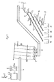
- the waste glass obtained is fed in the direction of arrow 1 via a funnel 2 to a crusher 3, in which the waste glass is comminuted in such a way that mostly fragments with an edge length of 5 to 50 mm are produced.
- the waste glass leaving the crusher 3 reaches a conveyor 4, to which a washing device 5 is assigned, by means of which the broken waste glass located on the conveyor 4 is acted upon by water jets 5a.
- a washing device 5 is assigned, by means of which the broken waste glass located on the conveyor 4 is acted upon by water jets 5a.
- the water provided with the above-mentioned impurities and glass splinters is passed over a separating or separating device not shown in the drawing, so that the water freed from the impurities and splinters can be fed to the washing device 5 again.
- washing device 5 instead of such a washing device 5, other cleaning devices would also be conceivable that work, for example, with air or sandblasting.
- the fragments remaining and washed on the conveyor enter a classifier 6, which is designed as a screen classifier and through which the supplied glass fragments are sorted into several fractions of different sizes.
- the fragments with an edge length below reach the classifier of 5 mm in the collecting container 7, from which they can be removed as a mixing glass for further processing.
- Sorted fragments with edge lengths of 5 to 50 mm are collected separately in the remaining collecting containers 8a to 8c, so that three fractions of different sized fragments are obtained, with differently colored glass fragments as well as porcelain, clay and ceramic fragments being mixed .
- each collecting container 8a to 8c is assigned a conveyor device 9 of this type, via which the glass fragments reaching this conveyor device are transferred into a storage container 10.
- Each storage container 10 is equipped with a device for separating the glass fragments fed to it.
- 1 shows such a separating device 11 in the form of a slide connected to the storage container 10.
- the separation of the fragments can take place, for example, in that the storage container 10 is designed as a vibrating vibration container with correspondingly installed baffles, which ensure that the glass fragments reach the slide 11 designed as a separation device and are then separated on the slide.
- the glass fragments From the separating device 11 in the form of the slide, the glass fragments reach a first inclined, channel-shaped slide 12, which in the example shown has two Holders 13 and 13a which can be transferred into the movement path of the fragments are equipped.
- Detection units 14 and 14a are arranged directly upstream of the hold-ups 13 and 13a in each case, with each detection unit consisting of light transmitters and receivers which are each active in two different levels.
- the detection units 14 and 14a are connected to evaluation electronics (not shown in FIG. 1) and central control devices for the individual detectors 13 and 13a.
- Each piece of glass fed to the trough-shaped chute 12 first reaches the pick-up 13 on its conveying path and is exposed there to the light beams of the two light transmitters effective in two planes in the rest position.
- the value of the light flow is measured in the evaluation electronics and, depending on this, the retainer 13 is either actuated so that the fragment is released for further movement on the conveyor trough 12 or is transferred from the conveyor trough 12 to a further conveyor trough 15 arranged downstream.
- the process already described in connection with the holder 13 is repeated in front of the holder 13a.
- the glass fragment is then either released by the retainer 13a either for further conveyance on the conveying trough 12 or transferred to the next conveying trough 15. Approved.
- the arrangement of the two retainers 13 and 13a in the course of the conveyor trough 12 is provided only for safety reasons in order to check the light transmittance measured by the detection unit 14 again by the detection unit 14a.
- Glass fragments made of colored glass and fragments made of other non-translucent material are transferred to the next slide 15 via the retainers 13 and 13a. You get on the slide 15 again in front of the support 13, 13a of this slide, only glass fragments of brown glass being conveyed on this slide, for example, in order to get into the sorting container 19.
- the glass fragments which are not made of brown glass are transferred via the retainers 13 and 13a of the slide 15 to the slide 16, on which fragments of green glass are released for further conveyance into the sorting container 20 by means of the retainers 13, 13a assigned to this slide.
- the fragments not made of green glass pass in the manner already described through the holders 13 and 13a assigned to the slide 16 onto the slide 17 and via this slide into the sorting container 21. Accordingly, non-transparent fragments, such as porcelain fragments, are placed in the sorting container 21. Clay or other ceramics are transferred as well as those broken glass that cannot be clearly identified as colorless or brown or green fragments due to paper or dirt parts still adhering.
- the slides 12 and 15 to 17 described and the sorting containers 18 to 21 assigned to them can be arranged in a plurality, for example in the form of a ring or in series, around the storage container 10, with several of the slides 12 assigned to one another and 15 to 17 can transfer the fragments into the same collection containers 18 to 21.
- the number of arrangements consisting of the chutes 12 and 15 to 17 per storage container thus determines the sorting capacity.
- the double arrangement of the retainers 13 and 13a described for the slide for each slide with the respectively assigned recognition unit 14 to 14a can be reduced to one retainer with an assigned recognition unit.
- the chutes 12 and 15 to 17 can be kept relatively narrow. They expediently have a U-shaped cross section with a width which corresponds to 1.3 to 1.4 times the maximum edge length of the fragments of the respective fraction. This prevents jamming of the fragments on the one hand, but on the other hand ensures that the fragments come to rest in front of the retainers 13 and 13a in the light beams of the light emitters of the detection units 14 and 14a, which are effective in two planes, and there in their rest position by determining the light flow can be identified.
- the length of the trough-shaped chutes 12 or 15 to 17 can be measured relatively short - in practice the chute 12 is about 1 m long, while the chutes 15 to 17 can be kept much shorter - despite the multiple arrangement of the chutes, there is none large amount of material is required.
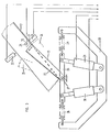
- FIG. 2 gives an enlarged view of the actual one already described in connection with FIG. 1
- Sorting device again, wherein in this illustration two of the slides 12 and 15 to 17, which are assigned to one another on the circumference in each case, are shown on the storage container 10.
- FIG. 2 two devices designed as vibrating troughs 11a for separating the fragments emerging from the storage container, for example a gap located in the bottom area, are shown below the storage container 10.
- the storage container 10 can in turn be designed as a vibration container, so that in the area of its bottom the broken glass emerges through an exit gap located there and is separated on the vibratory conveyors 11a and fed to the respective slides 12 via controlled flaps or retainers, as already mentioned in connection with Fig. 1 has been described.
- FIG. 2 shows the evaluation electronics and central control device 22, which is connected both to the detection units 14 and 14a and to the pickups 13 and 13a.
- the retainers 13 and 13a are designed as magnetically actuatable swivel parts and that in the bottom of the channel 12 and also the other channels 15 to 17 bottom openings 23 corresponding to the retainers 13 and 13a are provided.
- the retainers designed as swivel parts 13 can assume three different positions, of which the stopping position is shown in solid lines in FIG. 3.
- the retainer 13 closes the bottom opening 23 of the channel 12 in the plane of the floor, while in the position 25 moved through the bottom opening 23, the retainer 13 releases the bottom opening 23, so that one before in the holding position of the retainer 13 this lying fragment falls through the bottom opening 23 of the chute 12 onto the next channel and arrives in front of the next pick-up 13 assigned to this channel.
- the retainers 13 and 13a are connected in a rotationally secure manner at their end pointing in the conveying direction of the glass fragments to a two-armed lever 26, which in turn is mounted in a stationary manner in the pivot axis 27.
- the two-armed lever 26 is held in the example between oppositely acting springs 28 and 29 and is connected at the end of its two arms to an electromagnet 30 and 31, which has one end as well as the ends of the springs 28 and 29 are held in a stationary U-shaped component 32.
- the retainer 13 By actuating the electromagnets 30 and 31, the retainer 13 is transferred to the various positions and, after being released by the respective magnet, is returned via the springs 28 and 29 to the hold-open position drawn out in FIG. 3.
- one light transmitter 33 and 34 is arranged normal to the bottom of the slide 12 and the other light transmitter 35 and the associated light receiver are arranged perpendicularly to it.
- the light transmitter 35 and the light receiver assigned to it are provided just above the bottom of the chute 12, so that the light rays of the light transmitter 35 pass across the fragment lying at rest in front of the holder 13, while the rays emitted by the light transmitter 33 pass onto the Hit the flat side of the respective fragment.
- passage openings 36 and 37 are provided in the wall or the bottom, which are closed in a translucent manner.
- the electrical lines of the magnets 30 and 31 and the light transmitters and receivers 33 to 35 are connected to the electronics and central control unit 22 shown in FIG. 3 via the lines indicated in FIG. 3.
- All light guides 33 and 35 can be connected to a common one via glass fiber light guides
- Light source must be connected. All light guides can be exposed to colored light. However, it is also possible to partially convert the light emerging at the light guides into colored light only there. Experience has shown that increased security of separation of the glass fragments according to their colors can be achieved for all detection units by using red light.
- the described retainers 13 and 13a can also be provided instead of pivoting parts held in the bottom openings of the respective slides as side wall sections of the slides which can be pivoted in the manner of a switch, in which case the next following slide must then be arranged laterally next to the previous slide.
- the waste glass Before the waste glass is fed to the crusher 3, it is expediently passed over a classifier similar to the classifier 6 shown and described in FIG. 1, in order to already have small fragments with an edge length of less than 5 mm and fragments with an edge length of 5 to 50 mm Separate the feeder to the crusher from the remaining fragments and thereby sort the fragments with edge lengths of 5 to 50 mm in the same way as was described in connection with the classifier 6. In this way, only those fragments are fed to the crusher 3 that have an edge length greater than 50 mm exhibit. The fragments of the desired edge length for sorting contained in the waste glass are thus obtained directly from the waste glass without being passed through the crusher. In this way, the proportion of small fragments that cannot be sorted is avoided and the crusher is considerably relieved.
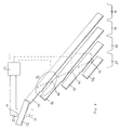
- FIG. 4 relates to a second alternative for a device according to the invention.
- the glass fragments of a certain fraction of approximately the same size are fed in via the chute 12 shown at the top left in FIG. 4.
- the bottom of the chute 12 is lined with glass, which reduces the friction of the glass fragments.
- the chute 12 can be vibrated.
- baffles (not shown) are provided, which may also transfer individual, still standing glass fragments into a flat position.
- the glass fragments can be further separated by thresholds.
- a light transmitter 33 and a light receiver 34 are provided in the region of the lower end of the slide 12.
- the light transmitter 33 is located above the slide 12, the light receiver 34 below the bottom of the slide 12.
- a reverse arrangement of the elements 33, 34 is also possible.
- the two elements are adjusted to one another in such a way that, in the case of an undisturbed radiation profile, those emitted by the light transmitter 33 Light rays hit the light receiver 34. Since the bottom of the slide 12 is made of glass, preferably colorless glass, such a beam path is readily possible.
- a piece of glass sliding on the chute 12 passes the light beam emitted by the light transmitter 33 due to the predetermined dimensions, a certain proportion of the light being absorbed in the piece of glass.
- the light receiver outputs a signal corresponding to the quantity of light received to an electronic evaluation unit 22. This thus receives a continuous course of time over the absorption taking place in the chute 12. As long as no glass fragment slides between light transmitter 33 and light receiver 34, a constant, undisturbed normal level is received. This value is not disturbed by the glass bottom of the chute 12 since it has a constant absorption value over the entire time.
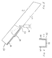
- These containers 18 to 21 can 4, in turn, are channels or slides that run perpendicular to the plane of the drawing in FIG. 4, taking up the glass fragments falling from further channels and slides 15 to 17b and finally ending up in larger collecting containers. For the sake of simplicity, only cross sections of these elements 18 to 21 are shown.
- the course of the slide 15 is equipped with a transfer device, which is formed here by a swivel part 40.
- the pivoting part 40 is controlled by the evaluation electronics 20 in its movement sequence.
- the swivel part 40 can assume two positions.
- the fragments falling on the chute 15 can allow unhindered passage into the sorting container 18.
- the swivel part 40 assumes the position shown in solid line in FIG. 4. This position can be seen more precisely in FIG. 5.
- the second possible position is shown in dashed lines in FIG. 4 and causes fragments sliding along the slide 15 to fall through the opening formed onto the next slide 16.
- This slide has a comparable structure and in turn has a swivel part 41 which can be controlled by the evaluation electronics 22 in two positions. In the position shown in broken lines, the glass fragment continues to fall onto the third slide 17, which also is constructed in this way and ultimately has a pivoting part 42 with which the fragments can reach the chute 17b and thus the sorting container 21.
- the evaluation electronics 22 can work, for example, in such a way that colorless glass passes undisturbed via the chute 15 into the container 18, while brown glass via the chute 16 into the container 19, green glass via the chute 17 into the container 20 and foreign parts, such as ceramic, get into the container 21 via the chute 17b.
- the evaluation electronics 22 If the evaluation electronics 22 detects with such a setting that a colorless glass fragment has passed the light transmitter 33 or the light receiver 34, it controls the pivoting part 40 in such a way that the bottom opening 23 of the slide 15 is closed and the glass fragment reaches the container 18 unhindered can.
- the control can be carried out in such a way that a switching takes place only when the swiveling parts 40, 41, 42 need to be changed. This extends the service life of the drives connected to the swivel parts 40, 41, 42 compared to a respective return to a normal position.
- the swivel part 40 only then must the swivel part 40 be switched to its open position Position if a fragment that is not identified as a colorless glass appears. As long as only colorless glass fragments are recognized by the evaluation electronics 22, the position of the swivel parts 41 and 42 is irrelevant and a change in position is therefore unnecessary.
- the control of the swivel parts 40, 41, 42 can also be set such that, in the event of defects in the drives, a predetermined position of the swivel parts is carried out in such a way that an enrichment of the container for colorless glass with stained glass or foreign parts is avoided in any case.
- a predetermined position of the swivel parts is carried out in such a way that an enrichment of the container for colorless glass with stained glass or foreign parts is avoided in any case.
- the quality of the colorless glass is kept constant even in the event of defects.
- feeding colorless glass into a stained glass container leads to a lower yield of colorless glass, but is less important for the quality of the stained glass.
- the swivel part 40 is connected at its end lying in the conveying direction of the glass fragments in a rotationally secure manner to a two-armed lever 43, which in turn is mounted in a stationary manner in the swivel axis 44.
- the two-armed lever 43 is connected to an electromagnet 44 as a drive.
- Fig. 6 it can be seen that the slide 15 is covered with glass on its bottom and on the side walls.
- the glass layers 48 consist of flat glass.
- the slides 12, 16, 17 and 17b have a similar structure.
Landscapes
- Health & Medical Sciences (AREA)
- General Health & Medical Sciences (AREA)
- Toxicology (AREA)
- Sorting Of Articles (AREA)
- Processing Of Solid Wastes (AREA)
Claims (18)
- Dispositif pour trier des déchets de verre, avec un concasseur (3) pour broyer les déchets de verre en morceaux d'une longueur d'arête maximale de 5 à 50 mm, un trieur de morceaux pour isoler les éclats et fragments d'une longueur d'arête inférieure à 5 mm, un convoyeur (9) qui transfère les morceaux à un séparateur (11), une unité de reconnaissance de couleur pour distinguer le verre transparent du verre coloré, et des récipients de triage (18 à 21) pour recevoir les morceaux de verre de différentes couleurs, caractérisé en ce que le concasseur (3) est suivi d'un classificateur (6) et des récipients collecteurs (7 et 8a à 8c) sont prévus pour plusieurs fractions de morceaux de différentes tailles,
en ce que les morceaux sont apportés par le séparateur (11) en continu et sans freinage à l'unité de reconnaissance de couleur, et traversent cette unité, sur des goulottes en forme de gouttières (12),
en ce que des goulottes supplémentaires en forme de gouttières (15 à 17) mènent de l'unité de reconnaissance de couleur aux récipients de triage (18 à 21),
et en ce que des dispositifs de transfert sont prévus à la suite de l'unité de reconnaissance de couleur, par lesquels, en fonction de valeurs de mesure de l'unité de reconnaissance de couleur, les morceaux sont transférés des premières goulottes en forme de gouttières (12) sur une des goulottes supplémentaires en forme de gouttières (15 à 17). - Dispositif pour trier des déchets de verre, avec un concasseur (3) pour broyer les déchets de verre en morceaux d'une longueur d'arête maximale de 5 à 50 mm, un trieur de morceaux pour isoler les éclats et fragments d'une longueur d'arête inférieure à 5 mm, un convoyeur (9) qui transfère les morceaux à un séparateur (11), une unité de reconnaissance de couleur pour distinguer le verre transparent du verre coloré, et des récipients de triage (18 à 21) pour recevoir les morceaux de verre de différentes couleurs, caractérisé en ce que le concasseur (3) est suivi d'un classificateur (6) et des récipients collecteurs (7 et 8a à 8c) sont prévus pour plusieurs fractions de morceaux de différentes tailles,
en ce que les morceaux quittent le séparateur (11) sur des goulottes en forme de gouttières (12),
en ce que les goulottes en forme de gouttières (12) sont équipées d'éléments de retenue (13, 13a) pouvant être transférés dans la voie de déplacement des morceaux, des unités de reconnaissance respectives (14, 14a) agissant dans deux plans différents étant disposées juste avant les éléments de retenue (13 et 13a),
et en ce que des dispositifs de transfert sont prévus à la suite des unités de reconnaissance de couleur, par lesquels, en fonction de valeurs de mesure de l'unité de reconnaissance de couleur, les morceaux sont relâchés sur la même goulotte en forme de gouttière ou transférés sur une autre goulotte et transportés plus loin dans les récipients de triage respectifs pour les différentes sortes de verre. - Dispositif selon la revendication 1 ou 2, caractérisé en ce que les unités de reconnaissance de couleur présentent chacune au moins un émetteur et un récepteur de lumière notamment rouge.
- Dispositif selon la revendication 3, caractérisé en ce que les émetteurs de lumière (33, 35) sont tous raccordés, par l'intermédiaire de fibres optiques, à une source lumineuse commune.
- Dispositif selon une des revendications précédentes, caractérisé en ce qu'un dispositif de nettoyage (5) est prévu entre le concasseur (3) et le classificateur (6).
- Dispositif selon une des revendications 3 à 5, caractérisé en ce que les goulottes (12 ; 15 à 17) présentent chacune une section en forme de U et une largeur qui correspond à 1,3 à 1,4 fois la longueur d'arête maximale des morceaux de la fraction respective, et en ce que les émetteurs et récepteurs de lumière (33 à 35) sont respectivement disposés au-dessus et en dessous du fond des goulottes (15 à 17).
- Dispositif selon une des revendications précédentes, caractérisé en ce que le fond des goulottes (12 ; 15 à 17) est réalisé en verre.
- Dispositif selon une des revendications précédentes, caractérisé en ce que le convoyeur (9) mène des récipients collecteurs (7 et 8a à 8c) à au moins un récipient de stockage (10) pour le transfert des morceaux des différentes fractions,
en ce que le séparateur (11) est associé au ou, selon le cas, à chaque récipient de stockage,
en ce que chaque séparateur (11) associé au récipient de stockage (10) est relié à une pluralité de goulottes,
et en ce qu'à chaque goulotte (12) partant du séparateur sont associées des goulottes supplémentaires (15 à 17) de configuration identique, sur lesquelles les différents morceaux peuvent être successivement transférés. - Dispositif selon les revendications 2 et 8, caractérisé en ce que les goulottes mutuellement associées sont disposées les unes au-dessus des autres et présentent des ouvertures de fond (23) pouvant être ouvertes et fermées par les éléments de retenue (13 ; 13a), les ouvertures de fond étant disposées en décalage de la goulotte supérieure vers la goulotte inférieure dans la direction de transport, et la goulotte la plus inférieure (17) étant réalisée sous forme de gouttière ininterrompue.
- Dispositif selon la revendication 9, caractérisé en ce que les éléments de retenue (13, 13a) sont réalisés sous la forme d'éléments pivotants pouvant être actionnés de façon électromagnétique ou pneumatique, maintenus dans l'ouverture de fond (23), pouvant être déplacés à travers cette ouverture et fermant l'ouverture de fond dans le plan du fond.
- Dispositif selon la revendication 10, caractérisé en ce que les éléments pivotants sont réalisés sous la forme de volets ou d'éléments pivotants avec un rétrécissement dirigé dans la direction de transport, et en ce que chaque élément pivotant est, à son extrémité dirigée dans la direction de transport, monté au moyen d'un axe de pivotement (27) sur un lever (26) à deux bras maintenu entre des ressorts (28, 29) agissant en sens contraires, un électro-aimant respectif (30, 31) agissant sur chacun des deux bras de ce levier.
- Dispositif selon une des revendications 9 à 11, caractérisé en ce qu'un émetteur et un récepteur de lumière sont disposés avant chaque ouverture de fond (23) de chaque goulotte (12 ; 15 ; 16), perpendiculairement à cette dernière, et des ouvertures de passage de lumière (36, 37) sont prévues dans la région de l'axe médian longitudinal du fond ainsi que dans les parois latérales de la goulotte, juste au-dessus du fond.
- Dispositif selon une des revendications 3 à 12, caractérisé en ce que le récepteur de lumière (34) est relié à une unité électronique d'évaluation (22), à laquelle il délivre en continu un signal caractérisant l'intensité lumineuse reçue, et en ce que l'unité électronique d'évaluation (22) est reliée au dispositif de transfert et transmet à ce dernier un signal de commande en fonction du signal reçu.
- Procédé pour trier des déchets de verre, les déchets de verre étant broyés en morceaux d'une longueur d'arête maximale de 5 à 50 mm et les morceaux d'une longueur d'arête inférieure à 5 mm étant isolés en tant que verre mélangé, tandis que les morceaux restants sont séparés un par un, les morceaux séparés un par un étant amenés à une unité de reconnaissance de couleur et les morceaux dont la couleur a été reconnue étant ensuite amenés à des récipients de triage respectivement affectés aux couleurs reconnues,
caractérisé en ce que les morceaux sont séparés d'après leur taille en plusieurs fractions, et en ce que les morceaux glissent sur des goulottes en forme de gouttières tandis qu'est effectuée la reconnaissance de couleur, et sont amenés sur des goulottes supplémentaires en forme de gouttières aux récipients de triage respectifs pour les différentes sortes de verre. - Procédé pour trier des déchets de verre, les déchets de verre étant broyés en morceaux d'une longueur d'arête maximale de 5 à 50 mm et les morceaux d'une longueur d'arête inférieure à 5 mm étant isolés en tant que verre mélangé, tandis que les morceaux restants sont séparés un par un, les morceaux séparés un par un étant amenés à une unité de reconnaissance de couleur et les morceaux dont la couleur a été reconnue étant ensuite amenés à des récipients de triage respectivement affectés aux couleurs reconnues,
caractérisé en ce que les morceaux sont séparés d'après leur taille en plusieurs fractions, en ce que les morceaux de chaque fraction sont immobilisés au cours de leur déplacement sur une goulotte en forme de gouttière et, afin de reconnaître leur couleur et leur transparence, sont exposés individuellement dans leur position immobile une ou plusieurs fois à des émetteurs et récepteurs de lumière respectifs agissant dans deux plans différents, et sont ensuite, en fonction de la valeur moyenne respective de la transmission de lumière, soit relâchés sur la même goulotte en forme de gouttière, soit transférés sur une autre goulotte et transportés plus loin dans les récipients de triage respectifs pour les différentes sortes de verre. - Procédé selon la revendication 14, caractérisé en ce que, pour déterminer la couleur d'un morceau, on ne se sert que de la partie médiane de la variation dans le temps de la courbe d'absorption du morceau.
- Procédé selon une des revendications 14 à 16, caractérisé en ce qu'afin de reconnaître leur couleur, les morceaux sont exposés à l'action de rayons lumineux de couleur, notamment rouges.
- Procédé selon une des revendications 14 à 17, caractérisé en ce que les morceaux sont nettoyés avant d'être amenés à l'unité de reconnaissance de couleur, notamment avant leur division en plusieurs fractions.
Applications Claiming Priority (2)
| Application Number | Priority Date | Filing Date | Title |
|---|---|---|---|
| DE3804391A DE3804391A1 (de) | 1988-02-12 | 1988-02-12 | Verfahren und vorrichtung zum sortieren von altglasbruchstuecken |
| DE3804391 | 1988-02-12 |
Publications (3)
| Publication Number | Publication Date |
|---|---|
| EP0328126A2 EP0328126A2 (fr) | 1989-08-16 |
| EP0328126A3 EP0328126A3 (en) | 1990-05-16 |
| EP0328126B1 true EP0328126B1 (fr) | 1996-04-17 |
Family
ID=6347287
Family Applications (1)
| Application Number | Title | Priority Date | Filing Date |
|---|---|---|---|
| EP89102317A Expired - Lifetime EP0328126B1 (fr) | 1988-02-12 | 1989-02-10 | Méthode et dispositif pour trier des déchets de verre |
Country Status (5)
| Country | Link |
|---|---|
| EP (1) | EP0328126B1 (fr) |
| AT (1) | ATE136817T1 (fr) |
| DE (2) | DE3804391A1 (fr) |
| ES (1) | ES2086305T3 (fr) |
| GR (1) | GR3019744T3 (fr) |
Families Citing this family (16)
| Publication number | Priority date | Publication date | Assignee | Title |
|---|---|---|---|---|
| DE4017130A1 (de) * | 1990-05-28 | 1991-12-05 | Seichter Gmbh | Einrichtung zum sortieren von glasbruchstuecken |
| DE4017128A1 (de) * | 1990-05-28 | 1991-12-05 | Seichter Gmbh | Einrichtung zum sortieren von glasbruchstuecken |
| DE4017126A1 (de) * | 1990-05-28 | 1991-12-05 | Seichter Gmbh | Einrichtung zum sortieren von glasbruchstuecken |
| DE4017127A1 (de) * | 1990-05-28 | 1991-12-05 | Seichter Gmbh | Einrichtung zum sortieren von glasbruchstuecken |
| DE59101351D1 (de) * | 1990-05-28 | 1994-05-19 | Seichter Gmbh | Sortiereinrichtung für Altglas. |
| DE4017503C2 (de) * | 1990-05-31 | 1999-03-18 | Zahoransky Anton Gmbh & Co | Hilfsvorrichtung insbesondere für eine Bürstenherstellungsmaschine |
| DE4019203A1 (de) * | 1990-06-15 | 1991-12-19 | Hubertus Exner | Verfahren und vorrichtung zum sortieren von altglas |
| DE9106292U1 (de) * | 1991-05-22 | 1991-07-18 | Glasrecycling Leeseringen GmbH & Co. KG, 3071 Estorf | Vorrichtung zum Sortieren von Altmaterial, insbesondere Altglas nach seiner Farbe |
| IT222662Z2 (it) * | 1991-07-04 | 1995-04-24 | Alcatel Face Spa | Dispositivo di smistamento in particolare per sistemi si smistamento a tasche |
| DE4210157C2 (de) * | 1992-03-27 | 1994-12-22 | Bodenseewerk Geraetetech | Verfahren zum Sortieren von Glasbruch |
| JPH07132269A (ja) * | 1993-11-10 | 1995-05-23 | Kanetsuu Eng Kk | カレット色別自動選別機及び選別方法 |
| FR2731368A1 (fr) * | 1995-03-09 | 1996-09-13 | Ind Propres D Aquitaine Sa Ipa | Procede et installation de traitement du verre. |
| DE19511901A1 (de) * | 1995-03-31 | 1996-10-02 | Commodas Gmbh | Vorrichtung und Verfahren zum Sortieren von Schüttgut |
| DE10143394A1 (de) * | 2001-09-04 | 2003-03-20 | Heckert Umwelttechnik Gmbh | Verfahren und Messanordnung zur Farberkennung und Anlage zum Sortieren farbiger Gegenstände |
| CN112974295A (zh) * | 2020-12-23 | 2021-06-18 | 汪成林 | 一种镜头镜片外观缺陷自动检测设备 |
| CN113426687A (zh) * | 2021-06-23 | 2021-09-24 | 安徽唯嵩光电科技有限公司 | 一种玻璃分选机物料输送装置 |
Citations (2)
| Publication number | Priority date | Publication date | Assignee | Title |
|---|---|---|---|---|
| EP0211139A2 (fr) * | 1985-08-05 | 1987-02-25 | Mabeg Müll- und Abfallbeseitigungs- gesellschaft mbH & Co. oHG. | Dispositif pour la séparation de déchets en verre, en particulier de bouteilles en verre transparent et en verre coloré |
| EP0248281A2 (fr) * | 1986-05-30 | 1987-12-09 | MAB Marlis Kellermann | Installation de tri de verre |
Family Cites Families (3)
| Publication number | Priority date | Publication date | Assignee | Title |
|---|---|---|---|---|
| US3802558A (en) * | 1973-04-02 | 1974-04-09 | Sortex North America | Refuse sorting and transparency sorting |
| JPS59147684A (ja) * | 1983-02-09 | 1984-08-24 | 株式会社 サタケ | 色彩選別機の流下樋装置 |
| FR2576008B1 (fr) * | 1985-01-16 | 1992-01-31 | Bsn | Dispositif de tri optique du groisil, pour obtenir du calcin, et installation comprenant de tels dispositifs |
-
1988
- 1988-02-12 DE DE3804391A patent/DE3804391A1/de not_active Withdrawn
-
1989
- 1989-02-10 DE DE58909653T patent/DE58909653D1/de not_active Expired - Fee Related
- 1989-02-10 AT AT89102317T patent/ATE136817T1/de not_active IP Right Cessation
- 1989-02-10 EP EP89102317A patent/EP0328126B1/fr not_active Expired - Lifetime
- 1989-02-10 ES ES89102317T patent/ES2086305T3/es not_active Expired - Lifetime
-
1996
- 1996-04-24 GR GR960401141T patent/GR3019744T3/el unknown
Patent Citations (2)
| Publication number | Priority date | Publication date | Assignee | Title |
|---|---|---|---|---|
| EP0211139A2 (fr) * | 1985-08-05 | 1987-02-25 | Mabeg Müll- und Abfallbeseitigungs- gesellschaft mbH & Co. oHG. | Dispositif pour la séparation de déchets en verre, en particulier de bouteilles en verre transparent et en verre coloré |
| EP0248281A2 (fr) * | 1986-05-30 | 1987-12-09 | MAB Marlis Kellermann | Installation de tri de verre |
Also Published As
| Publication number | Publication date |
|---|---|
| DE58909653D1 (de) | 1996-05-23 |
| DE3804391A1 (de) | 1989-08-24 |
| ATE136817T1 (de) | 1996-05-15 |
| EP0328126A2 (fr) | 1989-08-16 |
| GR3019744T3 (en) | 1996-07-31 |
| ES2086305T3 (es) | 1996-07-01 |
| EP0328126A3 (en) | 1990-05-16 |
Similar Documents
| Publication | Publication Date | Title |
|---|---|---|
| EP0328126B1 (fr) | Méthode et dispositif pour trier des déchets de verre | |
| AT398174B (de) | Verfahren und vorrichtung zum trennen von entrindeten holzknüppeln | |
| EP1253981B1 (fr) | Procede pour extraire des fractions metalliques d'un flux de matiere en vrac | |
| DE19519861C2 (de) | Verfahren und Vorrichtung zum Detektieren und Abführen von Fremdobjekten | |
| EP1763408B1 (fr) | Dispositif de detection pour identifier des objets dans un flux de matiere | |
| DE2413706A1 (de) | Verfahren und vorrichtung zum sortieren von glasabfaellen und -ausschuss auf transparenz | |
| DE3612076A1 (de) | Vorrichtung und anlage zum optischen sichten von unreinem glasbruch | |
| CH629018A5 (de) | Muenzsortiervorrichtung. | |
| DE69700944T2 (de) | Rutsche für Sortiereinrichtung | |
| EP0461616B1 (fr) | Procédé et dispositif de tri de déchets de verre | |
| AT399400B (de) | Verfahren und einrichtung zur bestimmung der reinheit von aufbereitetem altglas | |
| DE3514313C2 (de) | Verfahren und Vorrichtung zur Inspektion und zum Sortieren von Glasbehältern | |
| EP0897762B1 (fr) | Dispositif de tri de matériaux en vrac bruts, prétraités ou recyclés | |
| EP0248281B1 (fr) | Installation de tri de verre | |
| DE102017119137A1 (de) | Verfahren zur Detektion und Aussonderung von Sonderglas aus Recyclingglas | |
| EP0426893B1 (fr) | Procédé et dispositif de tri | |
| EP0211139B1 (fr) | Dispositif pour la séparation de déchets en verre, en particulier de bouteilles en verre transparent et en verre coloré | |
| DE19545240A1 (de) | Verfahren und Vorrichtung zum Trennen von Materialgemischen nach der Sorte | |
| EP1132992A1 (fr) | Détecteur de mesure de doses de rayons X et dispositif pour trier les batteries anciennes et/ou accumulateurs anciens par type | |
| DE3828067A1 (de) | Verfahren und vorrichtung zur aufbereitung von altglas | |
| EP0629979A2 (fr) | Dispositif de contrôle pour des pièces de monnaie | |
| DE3817026A1 (de) | Verfahren und einrichtung zum sortieren von altglas | |
| DE10123304A1 (de) | Vorrichtung und Verfahren zur Sortierung eines Abfallgemisches | |
| DE9106292U1 (de) | Vorrichtung zum Sortieren von Altmaterial, insbesondere Altglas nach seiner Farbe | |
| DE3731402A1 (de) | Anlage zur trennung von abfallhohlglaesern, insbesondere von flaschen mindestens nach weiss- und buntglas |
Legal Events
| Date | Code | Title | Description |
|---|---|---|---|
| PUAI | Public reference made under article 153(3) epc to a published international application that has entered the european phase |
Free format text: ORIGINAL CODE: 0009012 |
|
| AK | Designated contracting states |
Kind code of ref document: A2 Designated state(s): AT BE CH DE ES FR GB GR IT LI LU NL SE |
|
| 17P | Request for examination filed |
Effective date: 19890814 |
|
| PUAL | Search report despatched |
Free format text: ORIGINAL CODE: 0009013 |
|
| AK | Designated contracting states |
Kind code of ref document: A3 Designated state(s): AT BE CH DE ES FR GB GR IT LI LU NL SE |
|
| 17Q | First examination report despatched |
Effective date: 19920423 |
|
| GRAH | Despatch of communication of intention to grant a patent |
Free format text: ORIGINAL CODE: EPIDOS IGRA |
|
| GRAA | (expected) grant |
Free format text: ORIGINAL CODE: 0009210 |
|
| AK | Designated contracting states |
Kind code of ref document: B1 Designated state(s): AT BE CH DE ES FR GB GR IT LI LU NL SE |
|
| REF | Corresponds to: |
Ref document number: 136817 Country of ref document: AT Date of ref document: 19960515 Kind code of ref document: T |
|
| REG | Reference to a national code |
Ref country code: CH Ref legal event code: NV Representative=s name: KELLER & PARTNER PATENTANWAELTE AG |
|
| ITF | It: translation for a ep patent filed | ||
| REF | Corresponds to: |
Ref document number: 58909653 Country of ref document: DE Date of ref document: 19960523 |
|
| GBT | Gb: translation of ep patent filed (gb section 77(6)(a)/1977) |
Effective date: 19960520 |
|
| REG | Reference to a national code |
Ref country code: GR Ref legal event code: FG4A Free format text: 3019744 |
|
| REG | Reference to a national code |
Ref country code: ES Ref legal event code: FG2A Ref document number: 2086305 Country of ref document: ES Kind code of ref document: T3 |
|
| ET | Fr: translation filed | ||
| PLBE | No opposition filed within time limit |
Free format text: ORIGINAL CODE: 0009261 |
|
| STAA | Information on the status of an ep patent application or granted ep patent |
Free format text: STATUS: NO OPPOSITION FILED WITHIN TIME LIMIT |
|
| 26N | No opposition filed | ||
| PGFP | Annual fee paid to national office [announced via postgrant information from national office to epo] |
Ref country code: GR Payment date: 20010214 Year of fee payment: 13 |
|
| PGFP | Annual fee paid to national office [announced via postgrant information from national office to epo] |
Ref country code: LU Payment date: 20010216 Year of fee payment: 13 |
|
| PGFP | Annual fee paid to national office [announced via postgrant information from national office to epo] |
Ref country code: SE Payment date: 20010226 Year of fee payment: 13 |
|
| REG | Reference to a national code |
Ref country code: GB Ref legal event code: IF02 |
|
| PG25 | Lapsed in a contracting state [announced via postgrant information from national office to epo] |
Ref country code: LU Free format text: LAPSE BECAUSE OF NON-PAYMENT OF DUE FEES Effective date: 20020210 |
|
| PG25 | Lapsed in a contracting state [announced via postgrant information from national office to epo] |
Ref country code: SE Free format text: LAPSE BECAUSE OF NON-PAYMENT OF DUE FEES Effective date: 20020211 |
|
| PG25 | Lapsed in a contracting state [announced via postgrant information from national office to epo] |
Ref country code: GR Free format text: LAPSE BECAUSE OF NON-PAYMENT OF DUE FEES Effective date: 20020909 |
|
| EUG | Se: european patent has lapsed |
Ref document number: 89102317.8 |
|
| PGFP | Annual fee paid to national office [announced via postgrant information from national office to epo] |
Ref country code: GB Payment date: 20040210 Year of fee payment: 16 |
|
| PGFP | Annual fee paid to national office [announced via postgrant information from national office to epo] |
Ref country code: FR Payment date: 20040212 Year of fee payment: 16 |
|
| PGFP | Annual fee paid to national office [announced via postgrant information from national office to epo] |
Ref country code: NL Payment date: 20040216 Year of fee payment: 16 Ref country code: BE Payment date: 20040216 Year of fee payment: 16 |
|
| PGFP | Annual fee paid to national office [announced via postgrant information from national office to epo] |
Ref country code: DE Payment date: 20040217 Year of fee payment: 16 Ref country code: CH Payment date: 20040217 Year of fee payment: 16 |
|
| PGFP | Annual fee paid to national office [announced via postgrant information from national office to epo] |
Ref country code: ES Payment date: 20040223 Year of fee payment: 16 |
|
| PGFP | Annual fee paid to national office [announced via postgrant information from national office to epo] |
Ref country code: AT Payment date: 20040227 Year of fee payment: 16 |
|
| PG25 | Lapsed in a contracting state [announced via postgrant information from national office to epo] |
Ref country code: IT Free format text: LAPSE BECAUSE OF NON-PAYMENT OF DUE FEES;WARNING: LAPSES OF ITALIAN PATENTS WITH EFFECTIVE DATE BEFORE 2007 MAY HAVE OCCURRED AT ANY TIME BEFORE 2007. THE CORRECT EFFECTIVE DATE MAY BE DIFFERENT FROM THE ONE RECORDED. Effective date: 20050210 Ref country code: GB Free format text: LAPSE BECAUSE OF NON-PAYMENT OF DUE FEES Effective date: 20050210 Ref country code: AT Free format text: LAPSE BECAUSE OF NON-PAYMENT OF DUE FEES Effective date: 20050210 |
|
| PG25 | Lapsed in a contracting state [announced via postgrant information from national office to epo] |
Ref country code: ES Free format text: LAPSE BECAUSE OF NON-PAYMENT OF DUE FEES Effective date: 20050211 |
|
| PG25 | Lapsed in a contracting state [announced via postgrant information from national office to epo] |
Ref country code: LI Free format text: LAPSE BECAUSE OF NON-PAYMENT OF DUE FEES Effective date: 20050228 Ref country code: CH Free format text: LAPSE BECAUSE OF NON-PAYMENT OF DUE FEES Effective date: 20050228 Ref country code: BE Free format text: LAPSE BECAUSE OF NON-PAYMENT OF DUE FEES Effective date: 20050228 |
|
| BERE | Be: lapsed |
Owner name: *SEIFERT LOTHAR Effective date: 20050228 Owner name: *EXNER HUBERTUS Effective date: 20050228 |
|
| PG25 | Lapsed in a contracting state [announced via postgrant information from national office to epo] |
Ref country code: NL Free format text: LAPSE BECAUSE OF NON-PAYMENT OF DUE FEES Effective date: 20050901 Ref country code: DE Free format text: LAPSE BECAUSE OF NON-PAYMENT OF DUE FEES Effective date: 20050901 |
|
| GBPC | Gb: european patent ceased through non-payment of renewal fee |
Effective date: 20050206 |
|
| REG | Reference to a national code |
Ref country code: CH Ref legal event code: PL |
|
| PG25 | Lapsed in a contracting state [announced via postgrant information from national office to epo] |
Ref country code: FR Free format text: LAPSE BECAUSE OF NON-PAYMENT OF DUE FEES Effective date: 20051031 |
|
| NLV4 | Nl: lapsed or anulled due to non-payment of the annual fee |
Effective date: 20050901 |
|
| REG | Reference to a national code |
Ref country code: FR Ref legal event code: ST Effective date: 20051031 |
|
| REG | Reference to a national code |
Ref country code: ES Ref legal event code: FD2A Effective date: 20050211 |
|
| BERE | Be: lapsed |
Owner name: *SEIFERT LOTHAR Effective date: 20050228 Owner name: *EXNER HUBERTUS Effective date: 20050228 |