EP0328126B1 - Method and device for sorting spent glass - Google Patents
Method and device for sorting spent glass Download PDFInfo
- Publication number
- EP0328126B1 EP0328126B1 EP89102317A EP89102317A EP0328126B1 EP 0328126 B1 EP0328126 B1 EP 0328126B1 EP 89102317 A EP89102317 A EP 89102317A EP 89102317 A EP89102317 A EP 89102317A EP 0328126 B1 EP0328126 B1 EP 0328126B1
- Authority
- EP
- European Patent Office
- Prior art keywords
- fragments
- glass
- colour
- sorting
- chute
- Prior art date
- Legal status (The legal status is an assumption and is not a legal conclusion. Google has not performed a legal analysis and makes no representation as to the accuracy of the status listed.)
- Expired - Lifetime
Links
Images

Classifications
-
- B—PERFORMING OPERATIONS; TRANSPORTING
- B07—SEPARATING SOLIDS FROM SOLIDS; SORTING
- B07C—POSTAL SORTING; SORTING INDIVIDUAL ARTICLES, OR BULK MATERIAL FIT TO BE SORTED PIECE-MEAL, e.g. BY PICKING
- B07C5/00—Sorting according to a characteristic or feature of the articles or material being sorted, e.g. by control effected by devices which detect or measure such characteristic or feature; Sorting by manually actuated devices, e.g. switches
- B07C5/34—Sorting according to other particular properties
- B07C5/342—Sorting according to other particular properties according to optical properties, e.g. colour
-
- B—PERFORMING OPERATIONS; TRANSPORTING
- B07—SEPARATING SOLIDS FROM SOLIDS; SORTING
- B07C—POSTAL SORTING; SORTING INDIVIDUAL ARTICLES, OR BULK MATERIAL FIT TO BE SORTED PIECE-MEAL, e.g. BY PICKING
- B07C5/00—Sorting according to a characteristic or feature of the articles or material being sorted, e.g. by control effected by devices which detect or measure such characteristic or feature; Sorting by manually actuated devices, e.g. switches
- B07C5/34—Sorting according to other particular properties
- B07C5/3416—Sorting according to other particular properties according to radiation transmissivity, e.g. for light, x-rays, particle radiation
Definitions
- the invention relates to a device for sorting waste glass with a crusher for crushing waste glass into fragments up to an edge length of 5 - 50 mm, a fragment sorter for separating splinters and small parts with edge lengths below 5 mm, a conveyor device which separates the fragments into one Separation device transferred, a color recognition unit to differentiate between transparent and colored glass and sorting containers for holding the different colored glass fragments.
- the invention also relates to a method for sorting waste glass, wherein the waste glass is broken up into fragments up to an edge length of 5 to 50 mm and fragments with edge lengths below 5 mm are collected as mixed glass, and the remaining fragments are separated, the separated fragments are fed to a color detection unit and the color-coded fragments are then fed depending on the color-assigned sorting containers.
- Waste glass is usually in a mixture of different colored glass. A separation into the different color components is necessary for an economical recycling of the old glass. This applies in particular to colorless waste glass, since even small amounts of colored glass, such as green or brown glass, preclude recycling for the production of objects made of colorless glass. It is also important that the sorting of waste glass also reliably removes the non-glass components such as porcelain, earthenware or ceramic parts.
- a sorting system for sorting waste glass is known from US Pat. No. 3,802,558. This device reduces the size of the waste glass by means of pulverization, and then the fragments are cleaned. Small and very large glass fragments are sorted out, the rest in any size sorted in a photometric sorting device according to their color. The respective fragments are detected in free fall or with a horizontal component in free flight by appropriate color sensors.
- Sorting devices are known from FR 25 76 008 and EP 0 248 281 A2, with which complete glass bottles are fed to a sorter via a type of chute for separating ceramic parts.
- EP 0 211 139 A3 proposes a glass collection container in which complete bottles or hollow glass are sorted in the glass container during the collection, which makes them extremely heavy and costly.
- the invention has for its object to remedy this situation and to design a device and a method of the type mentioned in the introduction in such a way that with high utilization of the waste glass obtained a significantly better, i.e. glass of different colors is separated more securely.
- This object is achieved by a generic device in that the crusher is followed by a classifier and collecting containers for several fractions of differently sized fragments, that the fragments are fed continuously and unrestrained to the color recognition unit on channel-shaped slides and pass through them and that further channel-shaped ones pass through Guide slides from the color detection unit to the sorting containers and that the color detection unit is provided with transfer devices arranged downstream, with which the fragments are transferred from the first to one of the further channel-shaped slides depending on the measured values of the color detection unit.
- this object is achieved by a generic device in that the crusher is followed by a classifier and collecting container for several fractions fragments of different sizes are provided, that the fragments run on trough-shaped slides from the separating device, that the trough-shaped slides are equipped with two retainers which can be transferred into the path of movement of the fragments, effective detectors being arranged upstream of the detectors in each case on two different levels, and that the color detection unit Subsequent transfer device are provided with which, depending on the measured values of the color recognition unit, the fragments are released on the same trough-shaped slide or transferred to another slide and passed on to the respective sorting containers for the different types of glass.
- a method according to the invention is characterized in that the fragments are divided into several fractions in size, and that the fragments slide on trough-shaped slides while the color recognition is carried out and are fed to the respective sorting containers for the different types of glass on further trough-shaped slides.
- An alternative method according to the invention is characterized in that the fragments are divided into several fractions in size, that the fragments of each fraction are stopped in their movement on a trough-shaped slide and one or more times to recognize the color and light transmission of individual resting positions exposed to two different levels of light transmitters and receivers and depending on the respective mean value of the light flow then either released on the same trough-shaped slide or transferred to a different slide and forwarded to the respective sorting container for the different types of glass.
- the waste glass parts such as bottles, glasses and the like, as well as the fragments, are comminuted according to the invention, so that they have a maximum edge length, which in the known methods is already in the lower limit or below it .
- This crushing of the old glass parts or broken pieces creates shards that are mostly flat and level and sorted according to their size.
- the largely flat design of the small fragments means that they cannot be detected, as is possible with hollow glass fragments of larger dimensions depending on the shape and position of the fragment in the region of the detection unit.
- the absorption measurement provides a value which, based on an undisturbed normal level achieved in the absence of glass fragments, characterizes the amount of light which does not remain in the waste glass fragment due to absorption or other losses.
- the second alternative for a method according to the invention is characterized in that the fragments of each fraction for the detection of the color and light transmission are exposed individually or several times to light transmitters and receivers which are effective in two different levels and depending on the respective mean value of the light flow are fed to the sorting containers via the separate conveyors.
- the fragments are fed to the respective color recognition units according to fractions of the different sized fragments on slides.
- the different fractions of the fragments can be sorted simultaneously and separated into common sorting containers according to the color of the fragments, so that there again fragments of different dimensions but the same glass color to be collected.
- Non-glass components can be safely separated from the glass fragments due to their opacity and can be collected in a separate container.
- a cleaning device can be provided between the classifier and the crusher, for example a washing device in which the broken material acts on water becomes.
- the bottom of the slides is preferably lined with glass, which enables the glass fragments to be moved particularly smoothly and without friction.
- a particularly preferred embodiment of the slides is achieved in that the slides each have a U-shaped cross section with a width which corresponds to 1.3 to 1.4 times the maximum edge length of the fragments of the respective fraction, and that light transmitters and receivers are arranged above or below the bottom of the slides.
- the mutually assigned slides are arranged one above the other and have closable and releasable bottom openings by the retainer, the bottom openings being arranged offset from the upper to the lower slide in the conveying direction and the bottom slide is designed as a continuous channel.
- the supports are designed as electromagnetically or pneumatically operable, held in the bottom opening and movable through them and in a pivoting part closing the bottom opening in the plane of the bottom.
- the swivel parts are designed as flaps or swivel wedges with tapering in the conveying direction, and each swivel part is mounted at its end pointing in the conveying direction via a swivel axis on a two-armed lever held between springs acting in opposite directions, on each arm of which an electromagnet engages.
- the possibility of a particularly favorable arrangement of the light transmitter and receiver results from the fact that in a device with retainers in front of each floor opening of each slide a light transmitter and receivers are arranged normal to the bottom of the slide and a light transmitter and receiver are arranged perpendicularly to it and light passage openings are provided in the area of the central longitudinal line of the bottom and in the side walls of the slide just above the bottom.
- an arrangement of the light transmitters and receivers is preferred in which one of these two elements is arranged above and below the floor.
- the transfer device also has flaps or swivel wedges. However, these do not have the function of the above-mentioned pickup. These are flaps arranged in the bottom of the slide after the evaluation electronics. These only have to be switched back and forth between two positions or functions, namely a continuous position and an open position. In the continuous position, the bottom of the slide is closed by the flap, so that the fragments or fragments are unimpeded can pass through the slide to be fed to a sorting bin. In the open position, the fragments or fragments pass through the bottom of the channel-shaped slide onto a further slide underneath. This in turn is equipped with a flap, the position of which can be specified simultaneously by the evaluation electronics. Possibly. the fragments reach a third slide underneath.
- the number of slides can be selected depending on how many colors the glass fragments are to be split into. Usually a slide is provided for colorless, green and brown glass and one for ceramics and other non-glass components.
- the flaps can be designed as a simplified embodiment of the swivel parts provided in the first alternative.
- the drawing shows two exemplary embodiments of the invention in schematic representations.
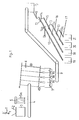
- the waste glass obtained is fed in the direction of arrow 1 via a funnel 2 to a crusher 3, in which the waste glass is comminuted in such a way that mostly fragments with an edge length of 5 to 50 mm are produced.
- the waste glass leaving the crusher 3 reaches a conveyor 4, to which a washing device 5 is assigned, by means of which the broken waste glass located on the conveyor 4 is acted upon by water jets 5a.
- a washing device 5 is assigned, by means of which the broken waste glass located on the conveyor 4 is acted upon by water jets 5a.
- the water provided with the above-mentioned impurities and glass splinters is passed over a separating or separating device not shown in the drawing, so that the water freed from the impurities and splinters can be fed to the washing device 5 again.
- washing device 5 instead of such a washing device 5, other cleaning devices would also be conceivable that work, for example, with air or sandblasting.
- the fragments remaining and washed on the conveyor enter a classifier 6, which is designed as a screen classifier and through which the supplied glass fragments are sorted into several fractions of different sizes.
- the fragments with an edge length below reach the classifier of 5 mm in the collecting container 7, from which they can be removed as a mixing glass for further processing.
- Sorted fragments with edge lengths of 5 to 50 mm are collected separately in the remaining collecting containers 8a to 8c, so that three fractions of different sized fragments are obtained, with differently colored glass fragments as well as porcelain, clay and ceramic fragments being mixed .
- each collecting container 8a to 8c is assigned a conveyor device 9 of this type, via which the glass fragments reaching this conveyor device are transferred into a storage container 10.
- Each storage container 10 is equipped with a device for separating the glass fragments fed to it.
- 1 shows such a separating device 11 in the form of a slide connected to the storage container 10.
- the separation of the fragments can take place, for example, in that the storage container 10 is designed as a vibrating vibration container with correspondingly installed baffles, which ensure that the glass fragments reach the slide 11 designed as a separation device and are then separated on the slide.
- the glass fragments From the separating device 11 in the form of the slide, the glass fragments reach a first inclined, channel-shaped slide 12, which in the example shown has two Holders 13 and 13a which can be transferred into the movement path of the fragments are equipped.
- Detection units 14 and 14a are arranged directly upstream of the hold-ups 13 and 13a in each case, with each detection unit consisting of light transmitters and receivers which are each active in two different levels.
- the detection units 14 and 14a are connected to evaluation electronics (not shown in FIG. 1) and central control devices for the individual detectors 13 and 13a.
- Each piece of glass fed to the trough-shaped chute 12 first reaches the pick-up 13 on its conveying path and is exposed there to the light beams of the two light transmitters effective in two planes in the rest position.
- the value of the light flow is measured in the evaluation electronics and, depending on this, the retainer 13 is either actuated so that the fragment is released for further movement on the conveyor trough 12 or is transferred from the conveyor trough 12 to a further conveyor trough 15 arranged downstream.
- the process already described in connection with the holder 13 is repeated in front of the holder 13a.
- the glass fragment is then either released by the retainer 13a either for further conveyance on the conveying trough 12 or transferred to the next conveying trough 15. Approved.
- the arrangement of the two retainers 13 and 13a in the course of the conveyor trough 12 is provided only for safety reasons in order to check the light transmittance measured by the detection unit 14 again by the detection unit 14a.
- Glass fragments made of colored glass and fragments made of other non-translucent material are transferred to the next slide 15 via the retainers 13 and 13a. You get on the slide 15 again in front of the support 13, 13a of this slide, only glass fragments of brown glass being conveyed on this slide, for example, in order to get into the sorting container 19.
- the glass fragments which are not made of brown glass are transferred via the retainers 13 and 13a of the slide 15 to the slide 16, on which fragments of green glass are released for further conveyance into the sorting container 20 by means of the retainers 13, 13a assigned to this slide.
- the fragments not made of green glass pass in the manner already described through the holders 13 and 13a assigned to the slide 16 onto the slide 17 and via this slide into the sorting container 21. Accordingly, non-transparent fragments, such as porcelain fragments, are placed in the sorting container 21. Clay or other ceramics are transferred as well as those broken glass that cannot be clearly identified as colorless or brown or green fragments due to paper or dirt parts still adhering.
- the slides 12 and 15 to 17 described and the sorting containers 18 to 21 assigned to them can be arranged in a plurality, for example in the form of a ring or in series, around the storage container 10, with several of the slides 12 assigned to one another and 15 to 17 can transfer the fragments into the same collection containers 18 to 21.
- the number of arrangements consisting of the chutes 12 and 15 to 17 per storage container thus determines the sorting capacity.
- the double arrangement of the retainers 13 and 13a described for the slide for each slide with the respectively assigned recognition unit 14 to 14a can be reduced to one retainer with an assigned recognition unit.
- the chutes 12 and 15 to 17 can be kept relatively narrow. They expediently have a U-shaped cross section with a width which corresponds to 1.3 to 1.4 times the maximum edge length of the fragments of the respective fraction. This prevents jamming of the fragments on the one hand, but on the other hand ensures that the fragments come to rest in front of the retainers 13 and 13a in the light beams of the light emitters of the detection units 14 and 14a, which are effective in two planes, and there in their rest position by determining the light flow can be identified.
- the length of the trough-shaped chutes 12 or 15 to 17 can be measured relatively short - in practice the chute 12 is about 1 m long, while the chutes 15 to 17 can be kept much shorter - despite the multiple arrangement of the chutes, there is none large amount of material is required.
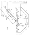
- FIG. 2 gives an enlarged view of the actual one already described in connection with FIG. 1
- Sorting device again, wherein in this illustration two of the slides 12 and 15 to 17, which are assigned to one another on the circumference in each case, are shown on the storage container 10.
- FIG. 2 two devices designed as vibrating troughs 11a for separating the fragments emerging from the storage container, for example a gap located in the bottom area, are shown below the storage container 10.
- the storage container 10 can in turn be designed as a vibration container, so that in the area of its bottom the broken glass emerges through an exit gap located there and is separated on the vibratory conveyors 11a and fed to the respective slides 12 via controlled flaps or retainers, as already mentioned in connection with Fig. 1 has been described.
- FIG. 2 shows the evaluation electronics and central control device 22, which is connected both to the detection units 14 and 14a and to the pickups 13 and 13a.
- the retainers 13 and 13a are designed as magnetically actuatable swivel parts and that in the bottom of the channel 12 and also the other channels 15 to 17 bottom openings 23 corresponding to the retainers 13 and 13a are provided.
- the retainers designed as swivel parts 13 can assume three different positions, of which the stopping position is shown in solid lines in FIG. 3.
- the retainer 13 closes the bottom opening 23 of the channel 12 in the plane of the floor, while in the position 25 moved through the bottom opening 23, the retainer 13 releases the bottom opening 23, so that one before in the holding position of the retainer 13 this lying fragment falls through the bottom opening 23 of the chute 12 onto the next channel and arrives in front of the next pick-up 13 assigned to this channel.
- the retainers 13 and 13a are connected in a rotationally secure manner at their end pointing in the conveying direction of the glass fragments to a two-armed lever 26, which in turn is mounted in a stationary manner in the pivot axis 27.
- the two-armed lever 26 is held in the example between oppositely acting springs 28 and 29 and is connected at the end of its two arms to an electromagnet 30 and 31, which has one end as well as the ends of the springs 28 and 29 are held in a stationary U-shaped component 32.
- the retainer 13 By actuating the electromagnets 30 and 31, the retainer 13 is transferred to the various positions and, after being released by the respective magnet, is returned via the springs 28 and 29 to the hold-open position drawn out in FIG. 3.
- one light transmitter 33 and 34 is arranged normal to the bottom of the slide 12 and the other light transmitter 35 and the associated light receiver are arranged perpendicularly to it.
- the light transmitter 35 and the light receiver assigned to it are provided just above the bottom of the chute 12, so that the light rays of the light transmitter 35 pass across the fragment lying at rest in front of the holder 13, while the rays emitted by the light transmitter 33 pass onto the Hit the flat side of the respective fragment.
- passage openings 36 and 37 are provided in the wall or the bottom, which are closed in a translucent manner.
- the electrical lines of the magnets 30 and 31 and the light transmitters and receivers 33 to 35 are connected to the electronics and central control unit 22 shown in FIG. 3 via the lines indicated in FIG. 3.
- All light guides 33 and 35 can be connected to a common one via glass fiber light guides
- Light source must be connected. All light guides can be exposed to colored light. However, it is also possible to partially convert the light emerging at the light guides into colored light only there. Experience has shown that increased security of separation of the glass fragments according to their colors can be achieved for all detection units by using red light.
- the described retainers 13 and 13a can also be provided instead of pivoting parts held in the bottom openings of the respective slides as side wall sections of the slides which can be pivoted in the manner of a switch, in which case the next following slide must then be arranged laterally next to the previous slide.
- the waste glass Before the waste glass is fed to the crusher 3, it is expediently passed over a classifier similar to the classifier 6 shown and described in FIG. 1, in order to already have small fragments with an edge length of less than 5 mm and fragments with an edge length of 5 to 50 mm Separate the feeder to the crusher from the remaining fragments and thereby sort the fragments with edge lengths of 5 to 50 mm in the same way as was described in connection with the classifier 6. In this way, only those fragments are fed to the crusher 3 that have an edge length greater than 50 mm exhibit. The fragments of the desired edge length for sorting contained in the waste glass are thus obtained directly from the waste glass without being passed through the crusher. In this way, the proportion of small fragments that cannot be sorted is avoided and the crusher is considerably relieved.
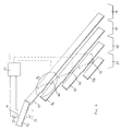
- FIG. 4 relates to a second alternative for a device according to the invention.
- the glass fragments of a certain fraction of approximately the same size are fed in via the chute 12 shown at the top left in FIG. 4.
- the bottom of the chute 12 is lined with glass, which reduces the friction of the glass fragments.
- the chute 12 can be vibrated.
- baffles (not shown) are provided, which may also transfer individual, still standing glass fragments into a flat position.
- the glass fragments can be further separated by thresholds.
- a light transmitter 33 and a light receiver 34 are provided in the region of the lower end of the slide 12.
- the light transmitter 33 is located above the slide 12, the light receiver 34 below the bottom of the slide 12.
- a reverse arrangement of the elements 33, 34 is also possible.
- the two elements are adjusted to one another in such a way that, in the case of an undisturbed radiation profile, those emitted by the light transmitter 33 Light rays hit the light receiver 34. Since the bottom of the slide 12 is made of glass, preferably colorless glass, such a beam path is readily possible.
- a piece of glass sliding on the chute 12 passes the light beam emitted by the light transmitter 33 due to the predetermined dimensions, a certain proportion of the light being absorbed in the piece of glass.
- the light receiver outputs a signal corresponding to the quantity of light received to an electronic evaluation unit 22. This thus receives a continuous course of time over the absorption taking place in the chute 12. As long as no glass fragment slides between light transmitter 33 and light receiver 34, a constant, undisturbed normal level is received. This value is not disturbed by the glass bottom of the chute 12 since it has a constant absorption value over the entire time.
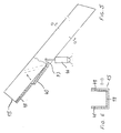
- These containers 18 to 21 can 4, in turn, are channels or slides that run perpendicular to the plane of the drawing in FIG. 4, taking up the glass fragments falling from further channels and slides 15 to 17b and finally ending up in larger collecting containers. For the sake of simplicity, only cross sections of these elements 18 to 21 are shown.
- the course of the slide 15 is equipped with a transfer device, which is formed here by a swivel part 40.
- the pivoting part 40 is controlled by the evaluation electronics 20 in its movement sequence.
- the swivel part 40 can assume two positions.
- the fragments falling on the chute 15 can allow unhindered passage into the sorting container 18.
- the swivel part 40 assumes the position shown in solid line in FIG. 4. This position can be seen more precisely in FIG. 5.
- the second possible position is shown in dashed lines in FIG. 4 and causes fragments sliding along the slide 15 to fall through the opening formed onto the next slide 16.
- This slide has a comparable structure and in turn has a swivel part 41 which can be controlled by the evaluation electronics 22 in two positions. In the position shown in broken lines, the glass fragment continues to fall onto the third slide 17, which also is constructed in this way and ultimately has a pivoting part 42 with which the fragments can reach the chute 17b and thus the sorting container 21.
- the evaluation electronics 22 can work, for example, in such a way that colorless glass passes undisturbed via the chute 15 into the container 18, while brown glass via the chute 16 into the container 19, green glass via the chute 17 into the container 20 and foreign parts, such as ceramic, get into the container 21 via the chute 17b.
- the evaluation electronics 22 If the evaluation electronics 22 detects with such a setting that a colorless glass fragment has passed the light transmitter 33 or the light receiver 34, it controls the pivoting part 40 in such a way that the bottom opening 23 of the slide 15 is closed and the glass fragment reaches the container 18 unhindered can.
- the control can be carried out in such a way that a switching takes place only when the swiveling parts 40, 41, 42 need to be changed. This extends the service life of the drives connected to the swivel parts 40, 41, 42 compared to a respective return to a normal position.
- the swivel part 40 only then must the swivel part 40 be switched to its open position Position if a fragment that is not identified as a colorless glass appears. As long as only colorless glass fragments are recognized by the evaluation electronics 22, the position of the swivel parts 41 and 42 is irrelevant and a change in position is therefore unnecessary.
- the control of the swivel parts 40, 41, 42 can also be set such that, in the event of defects in the drives, a predetermined position of the swivel parts is carried out in such a way that an enrichment of the container for colorless glass with stained glass or foreign parts is avoided in any case.
- a predetermined position of the swivel parts is carried out in such a way that an enrichment of the container for colorless glass with stained glass or foreign parts is avoided in any case.
- the quality of the colorless glass is kept constant even in the event of defects.
- feeding colorless glass into a stained glass container leads to a lower yield of colorless glass, but is less important for the quality of the stained glass.
- the swivel part 40 is connected at its end lying in the conveying direction of the glass fragments in a rotationally secure manner to a two-armed lever 43, which in turn is mounted in a stationary manner in the swivel axis 44.
- the two-armed lever 43 is connected to an electromagnet 44 as a drive.
- Fig. 6 it can be seen that the slide 15 is covered with glass on its bottom and on the side walls.
- the glass layers 48 consist of flat glass.
- the slides 12, 16, 17 and 17b have a similar structure.
Landscapes
- Health & Medical Sciences (AREA)
- General Health & Medical Sciences (AREA)
- Toxicology (AREA)
- Sorting Of Articles (AREA)
- Processing Of Solid Wastes (AREA)
Abstract
Description
Die Erfindung betrifft eine Vorrichtung zum Sortieren von Altglas mit einem Brecher zur Zerkleinerung von Altglas in Bruchstücke bis auf eine Kantenlänge von 5 - 50 mm, einem Bruchstücksortierer zur Abtrennung von Splittern und Kleinteilen mit Kantenlängen unter 5 mm, einer Fördereinrichtung, die die Bruchstücke zu einer Vereinzelungseinrichtung überführt, einer Farberkennungseinheit zur Unterscheidung von durchsichtigem und farbigem Glas und Sortierbehältem zur Aufnahme der unterschiedlichen gefärbten Glasbruchstücke.The invention relates to a device for sorting waste glass with a crusher for crushing waste glass into fragments up to an edge length of 5 - 50 mm, a fragment sorter for separating splinters and small parts with edge lengths below 5 mm, a conveyor device which separates the fragments into one Separation device transferred, a color recognition unit to differentiate between transparent and colored glass and sorting containers for holding the different colored glass fragments.
Die Erfindung betrifft außerdem ein Verfahren zum Sortieren von Altglas, wobei das Altglas in Bruchstücke bis auf eine Kantenlänge von 5 bis 50 mm zerkleinert und Bruchstücke mit Kantenlängen unter 5 mm als Mischglas gesammelt, und die verbleibenden Bruchstücke vereinzelt, die vereinzelten Bruchstücke einer Farberkennungseinheit zugeführt und die farblich erkannten Bruchstücke anschließend abhängig von der erkannten Farbe zugeordneten Sortierbehältern zugeführt werden.The invention also relates to a method for sorting waste glass, wherein the waste glass is broken up into fragments up to an edge length of 5 to 50 mm and fragments with edge lengths below 5 mm are collected as mixed glass, and the remaining fragments are separated, the separated fragments are fed to a color detection unit and the color-coded fragments are then fed depending on the color-assigned sorting containers.
Altglas liegt üblicherweise in einem Gemisch aus verschiedenfarbigem Glas vor. Für eine wirtschaftliche Wiederverwertung des Altglases ist eine Trennung in die unterschiedlichen Farbbestandteile erforderlich. Dies gilt in besonderem Maße für farbloses Altglas, da bereits geringe Anteile von farbigem Glas, wie grünem oder braunem Glas, eine Wiederverwertung zur Herstellung von Gegenständen aus farblosem Glas ausschließen. Wichtig ist fernerhin, daß bei der Sortierung von Altglas auch die nicht aus Glas bestehenden Bestandteile, wie Porzellane, Steingut- oder Keramikteile, sicher aussortiert werden.Waste glass is usually in a mixture of different colored glass. A separation into the different color components is necessary for an economical recycling of the old glass. This applies in particular to colorless waste glass, since even small amounts of colored glass, such as green or brown glass, preclude recycling for the production of objects made of colorless glass. It is also important that the sorting of waste glass also reliably removes the non-glass components such as porcelain, earthenware or ceramic parts.
Bei bekannten Verfahren zum Sortieren von Altglas (DE 33 26 129 A1; DE 34 45 428 A1) werden die Altglasbruchstücke, insbesondere Bruchstücke aus Hohlglas bzw. auch die gesamten Alt-Hohlglasbehälter, wie Flaschen, in der jeweils angefallenen Größe vereinzelt und durch eine Erkennungseinheit mit einem Lichtsender und -empfänger hindurchgefördert sowie mittels einer Auswertelektronik nach Farben getrennt auf voneinander getrennten Förderem in Sortierbehälter überführt. Bei den bekannten Verfahren müssen die Altglasteile, um von der Erkennungseinheit hinsichtlich ihrer Farbe sicher erfaßt zu werden, relativ groß sein. Glasstücke von nur wenigen cm Kantenlänge lassen sich mit den bekannten Verfahren nicht sortieren, so daß diese Bruchstücke für die Wiederverwertung verlorengehen. Aber auch größere Glasbruchstücke sind mit den bekannten Verfahren nicht sicher zu trennen, weil die Bruchstücke in sehr unterschiedlichen Positionen an der Erkennungseinheit vorbei durch den Strahlenweg zwischen Lichtsender und -empfänger hindurchgefördert werden und hierdurch Bruchstücke etwa gleicher Formgebung und gleicher Farbe zu sehr unterschiedlichen Werten des Lichtdurchflusses führen. Flache und hochkant parallel zu den Lichtstrahlen durch die Erkennungseinheit hindurchgeförderte Bruchstücke werden vielfach nicht erkannt und somit nicht dem richtigen Sortierbehälter zugeführt. Dies gilt auch für gewölbte größere Bruchstücke, an denen je nach ihrer Lage die Lichtstrahlen vorbeigehen können.In known methods for sorting waste glass (
Aus der US-PS 3 802 558 ist eine Sortieranlage für das Sortieren von Altglas bekannt. Diese Vorrichtung verkleinert mittels eines Pulverisierens das Altglas, anschließend werden die Bruchstücke gereinigt. Ganz kleine sowie ganz große Glasbruchstücke werden ausgesondert, der gesamte Rest in beliebiger Größe in einer fotometrischen Sortiervorrichtung nach ihrer Farbe sortiert. Die jeweiligen Bruchstücke werden in freiem Fall bzw. mit Horizontalkomponente in freiem Flug durch entsprechende Farbsensoren detektiert.A sorting system for sorting waste glass is known from US Pat. No. 3,802,558. This device reduces the size of the waste glass by means of pulverization, and then the fragments are cleaned. Small and very large glass fragments are sorted out, the rest in any size sorted in a photometric sorting device according to their color. The respective fragments are detected in free fall or with a horizontal component in free flight by appropriate color sensors.
Die sehr unregelmäßig geformten und auch unterschiedlich schweren Glasbruchstücke, die unvorhersehbar im Brecher entstehen, reagieren ja nach ihrer zufälligen jeweiligen Position in der Flugbahn sehr unterschiedlich auf die Fotodetektoren. So könnte es durchaus vorkommen, daß ein beispielsweise flächiges Bruchstück gerade senkrecht zum Lichtstrahl eines Fotodetektors diesen durchquert, das nächste genauso geformte jedoch so, daß der Strahl genau durch die Fläche verläuft. Glasbruchstücke weisen aber auch abhängig von Größe und Form in dem dadurch entstehenden Luftwiderstand sehr unterschiedliche Flugbahnen auf, da jeweils verschiedene Parabeln beschrieben werden. Beide Effekte beeinträchtigen die Genauigkeit der Anlage ganz erheblich, unter Umständen um Fehler von 500 oder mehr Prozent.The very irregularly shaped and also differently heavy glass fragments, which arise unpredictably in the crusher, react very differently to the photo detectors depending on their random position in the trajectory. So it could well happen that a flat fragment, for example, passes straight through to the light beam of a photodetector, but the next one is shaped in the same way so that the beam runs exactly through the surface. Glass fragments also have very different trajectories depending on their size and shape in the resulting air resistance, since different parabolas are described in each case. Both effects significantly affect the accuracy of the system, possibly by errors of 500 or more percent.
Aus der FR 25 76 008 und der EP 0 248 281 A2 sind Sortiervorrichtungen bekannt, mit denen komplette Glasflaschen über eine Art Rutsche einem Sortierer zum Aussondem von Keramikanteilen zugeführt werden.Sorting devices are known from
Die EP 0 211 139 A3 schlägt einen Glassammelcontainer vor, bei dem komplette Flaschen bzw. Hohlglas während des Sammelns im Glascontainer sortiert werden, was diese außerordentlich schwer und kostspielig macht.EP 0 211 139 A3 proposes a glass collection container in which complete bottles or hollow glass are sorted in the glass container during the collection, which makes them extremely heavy and costly.
Theoretische Überlegungen zur Trennung von Weißglas von Farbglas werden von Rudolf Germer in: "Messen + Prüfen", Band 19 (1983) Seite 286, angestellt. Lösungsvorschläge werden nicht gegeben.Theoretical considerations on the separation of white glass from colored glass are made by Rudolf Germer in: "Measure + Check", Volume 19 (1983) page 286. Proposed solutions are not given.
Erfahrungen haben gezeigt, daß mit den bisherigen Verfahren der Reinheitsgrad des farblosen Altglases durch Vermischung mit Buntglas unbefriedigend ist und in den meisten Fällen nicht ausreicht, um dieses Altglas für die erneute Herstellung von Gegenständen aus farblosem Glas zu verwenden.Experience has shown that with the previous processes, the degree of purity of the colorless waste glass by mixing with stained glass is unsatisfactory and in most cases is not sufficient to use this waste glass for the renewed manufacture of objects from colorless glass.
Der Erfindung liegt die Aufgabe zugrunde, hier Abhilfe zu schaffen und eine Vorrichtung und ein Verfahren der einleitend genannten Art so auszubilden, daß bei hoher Ausnutzung des anfallenden Altglases eine wesentlich bessere, d.h. sicherere Trennung des Glases der verschiedenen Farben erfolgt.The invention has for its object to remedy this situation and to design a device and a method of the type mentioned in the introduction in such a way that with high utilization of the waste glass obtained a significantly better, i.e. glass of different colors is separated more securely.
Diese Aufgabe wird durch eine gattungsgemäße Vorrichtung dadurch gelöst, daß dem Brecher ein Klassierer nachgeordnet und Sammelbehälter für mehrere Fraktionen unterschiedlich großer Bruchstücke vorgesehen sind, daß von der Vereinzelungseinrichtung auf rinnenförmigen Rutschen die Bruchstücke stetig und ungebremst der Farberkennungseinheit zugeführt werden und diese durchlaufen und daß weitere rinnenförmige Rutschen von der Farberkennungseinheit zu den Sortierbehältern führen und daß der Farberkennungseinheit nachgeordnete Überführungseinrichtungen vorgesehen sind, mit denen in Abhängigkeit von Meßwerten der Farberkennungseinheit die Bruchstücke von der ersten auf eine der weiteren rinnenförmigen Rutschen überführt werden.This object is achieved by a generic device in that the crusher is followed by a classifier and collecting containers for several fractions of differently sized fragments, that the fragments are fed continuously and unrestrained to the color recognition unit on channel-shaped slides and pass through them and that further channel-shaped ones pass through Guide slides from the color detection unit to the sorting containers and that the color detection unit is provided with transfer devices arranged downstream, with which the fragments are transferred from the first to one of the further channel-shaped slides depending on the measured values of the color detection unit.
Alternativ wird diese Aufgabe durch eine gattungsgemäße Vorrichtung dadurch gelöst, daß dem Brecher ein Klassierer nachgeordnet und Sammelbehälter für mehrere Fraktionen unterschiedlich großer Bruchstücke vorgesehen sind, daß von der Vereinzelungseinrichtung die Bruchstücke auf rinnenförmigen Rutschen laufen, daß die rinnenförmigen Rutschen mit zwei in die Bewegungsbahn der Bruchstücke überführbaren Aufhaltern ausgerüstet sind, wobei den Aufhaltern jeweils in zwei verschiedenen Ebenen wirksame Erkennungseinheiten unmittelbar vorgeordnet, und daß der Farberkennungseinheit nachgeordnete Überführungseinrichtung vorgesehen sind, mit denen in Abhängigkeit von Meßwerten der Farberkennungseinheit die Bruchstücke auf der gleichen rinnenförmigen Rutsche freigegeben oder auf eine andere Rutsche überführt und in die jeweiligen Sortierbehälter für die unterschiedlichen Glassorten weitergeleitet werden.Alternatively, this object is achieved by a generic device in that the crusher is followed by a classifier and collecting container for several fractions fragments of different sizes are provided, that the fragments run on trough-shaped slides from the separating device, that the trough-shaped slides are equipped with two retainers which can be transferred into the path of movement of the fragments, effective detectors being arranged upstream of the detectors in each case on two different levels, and that the color detection unit Subsequent transfer device are provided with which, depending on the measured values of the color recognition unit, the fragments are released on the same trough-shaped slide or transferred to another slide and passed on to the respective sorting containers for the different types of glass.
Ein erfindungsgemäßes Verfahren zeichnet sich dadurch aus, daß die Bruchstücke der Größe nach in mehrere Fraktionen unterteilt werden, und daß die Bruchstücke auf rinnenförmigen Rutschen gleiten, während die Farberkennung durchgeführt wird und auf weiteren rinnenförmigen Rutschen den jeweiligen Sortierbehältern für die unterschiedlichen Glassorten zugeführt werden.A method according to the invention is characterized in that the fragments are divided into several fractions in size, and that the fragments slide on trough-shaped slides while the color recognition is carried out and are fed to the respective sorting containers for the different types of glass on further trough-shaped slides.
Ein alternatives erfindungsgemäßes Verfahren zeichnet sich dadurch aus, daß die Bruchstücke der Größe nach in mehrere Fraktionen unterteilt werden, daß die Bruchstücke jeder Fraktion in ihrer Bewegung auf einer rinnenförmigen Rutsche gestoppt werden und zur Erkennung der Farb- und Lichtdurchlässigkeit einzelner ruhender Position ein- oder mehrfach je in zwei verschiedenen Ebenen wirkenden Lichtsendern und -empfängern ausgesetzt und abhängig von dem jeweiligen Mittelwert des Lichtdurchflusses dann entweder auf der gleichen rinnenförmigen Rutsche freigegeben oder auf eine andere Rutsche überführt und in die jeweiligen Sortierbehälter für die unterschiedlichen Glassorten weitergeleitet werden.An alternative method according to the invention is characterized in that the fragments are divided into several fractions in size, that the fragments of each fraction are stopped in their movement on a trough-shaped slide and one or more times to recognize the color and light transmission of individual resting positions exposed to two different levels of light transmitters and receivers and depending on the respective mean value of the light flow then either released on the same trough-shaped slide or transferred to a different slide and forwarded to the respective sorting container for the different types of glass.
Im Gegensatz zu den bekannten Vorrichtungen und Verfahren werden erfindungsgemäß die anfallenden Altglasanteile, wie Flaschen, Gläser und dergleichen, sowie auch die Bruchstücke zerkleinert, so daß sie eine maximale Kantenlänge aufweisen, die bei den bekannten Verfahren bereits im Bereich der unteren Grenze oder unterhalb derselben liegt. Durch diese Zerkleinerung der Altglasteile bzw. Bruchtücke entstehen Scherben, die überwiegend flach und eben ausgebildet sind und nach ihrer Größe sortiert werden.In contrast to the known devices and methods, the waste glass parts, such as bottles, glasses and the like, as well as the fragments, are comminuted according to the invention, so that they have a maximum edge length, which in the known methods is already in the lower limit or below it . This crushing of the old glass parts or broken pieces creates shards that are mostly flat and level and sorted according to their size.
Dadurch, daß diese relativ kleinen Scheiben der Farberkennungseinheit ausgesetzt werden, ist bei der weitgehend ebenen Ausbildung der kleinen Bruchstücke ausgeschlossen, daß sie nicht erfaßt werden, wie dies bei Hohlglasbruchstücken größerer Abmessungen je nach Form und Lage des Bruchstückes im Bereich der Erkennungseinheit möglich ist.Because these relatively small panes are exposed to the color detection unit, the largely flat design of the small fragments means that they cannot be detected, as is possible with hollow glass fragments of larger dimensions depending on the shape and position of the fragment in the region of the detection unit.
Eine Reinigung der Bruchstücke vor der Zufuhr zur Farberkennungseinheit verbessert die Sicherheit der Messung weiter; da anhaltender Schmutz oder Papierreste entfernt werden.Cleaning the fragments before they are fed to the color recognition unit further improves the safety of the measurement; because persistent dirt or paper residues are removed.
Es hat sich als zweckmäßig erwiesen, wenn die Bruchstücke zur Erkennung der Farbe und Lichtdurchlässigkeit der Einwirkung farbiger Lichtstrahlen des Lichtsenders ausgesetzt werden. Hierdurch ergeben sich größere Unterschiede des Lichtdurchflusses bei den verschiedenfarbigen Bruchstücken. Versuche haben gezeigt, daß nicht nur eine Verbesserung der Trennung der Bruchstücke aus farblosem Glas von solchen aus Buntglas erreicht wird, sondern auch der Trenneffekt zwischen Bruchstücken aus braunem und grünem Glas verbessert wird.It has proven to be expedient if the fragments are exposed to the action of colored light rays from the light transmitter in order to recognize the color and translucency. This results in larger differences in the light flow in the differently colored fragments. Experiments have shown that not only is the separation of the fragments of colorless glass from those of stained glass improved, but the separation effect between fragments of brown and green glass is also improved.
Zwei unterschiedliche Verfahrensalternativen haben sich bewährt. Eine Alternative besteht darin, daß die vereinzelten Bruchstücke der Farberkennungseinheit stetig und ungebremst zugeführt werden und diese durchlaufen, und daß die Farberkennungseinheit während des Durchlaufens des Bruchstückes ein Absorptionssignal aufnimmt und einer Auswerteelektronik zuführt, die aus der Absorptionskurve die Bestimmung der Farbe des Bruchstückes vornimmt.Two different process alternatives have proven their worth. An alternative is that the individual fragments are fed to the color recognition unit continuously and unrestrained and pass through them, and that the color recognition unit receives an absorption signal during the passage of the fragment and feeds it to evaluation electronics that determine the color of the fragment from the absorption curve.
Besonders günstig ist es dann, wenn aus dem zeitlichen Verlauf der Absorptionskurve eines Bruchstückes nur der mittlere Bereich zur Bestimmung der Farbe des Bruchstückes herangezogen wird.It is particularly expedient if, from the time course of the absorption curve of a fragment, only the middle area is used to determine the color of the fragment.
Die Absorptionsmessung liefert einen Wert, der ausgehend von einem bei Nichtvorhandensein von Glasbruchstücken erzielten ungestörten Normalpegel diejenige Lichtmenge charakterisiert, die nicht durch Absorption oder andere Verluste in dem Altglasbruchstück verbleibt.The absorption measurement provides a value which, based on an undisturbed normal level achieved in the absence of glass fragments, characterizes the amount of light which does not remain in the waste glass fragment due to absorption or other losses.
Folgende Richtlinien ergeben sich dabei ganz zwanglos: Farbloses, klares Altglas absorbiert zwar Licht und wird dadurch als vorhanden erkannt, es absorbiert jedoch deutlich weniger Licht als braunes oder grünes Altglas. Dieser Effekt kann noch durch die Wahl bestimmter farbiger, insbesondere roter Lichtfrequenzen verstärkt werden. Außerdem laßt sich dadurch auch eine verbesserte Unterscheidung von grünem und braunem Glas erzielen.The following guidelines are quite informal: Colorless, clear waste glass absorbs light and is recognized as existing, but it absorbs significantly less light than brown or green waste glass. This effect can be enhanced by the selection of certain colored, especially red, light frequencies. In addition, an improved distinction between green and brown glass can be achieved.
Die Unterschiede sind bei diesem Meßverfahren so groß, daß eine typische Fehlerquelle praktisch völlig ausgeschieden wird. So ist normalerweise natürlich die Absorption eines dicken Glases größer als die eines dünnen Glases.The differences in this measuring method are so great that a typical source of error is practically eliminated. Of course, the absorption of a thick glass is normally greater than that of a thin glass.
Aufgrund der Zerkleinerung in etwa gleichgroße (aufgrund der Klassierung) im wesentlichen flache Bruchstücke ist jedoch sichergestellt, daß nicht wie bei ungünstig liegenden unregelmäßig geformten Flaschen eine Vielfachdurchstrahlung ein und derselben Glasschicht erfolgt. Selbst sehr dickes, farbloses Glas besitzt jedoch immer noch einen deutlich niedrigeren Absorptionswert als dünnes Buntglas. Eine sichere Trennung wird dadurch möglich.Due to the crushing of roughly the same size (due to the classification) of essentially flat fragments, however, it is ensured that, as in the case of unfavorably located irregularly shaped bottles, multiple radiation of one and the same glass layer does not occur. However, even very thick, colorless glass still has a significantly lower absorption value than thin stained glass. This enables a safe separation.
Auch gelegentlich im Altglas vorkommende nur leicht getönte Glasbestandteile können so ausgesondert werden.Even lightly tinted glass components that occasionally appear in the old glass can be separated out in this way.
Eine weitere Verbesserung tritt durch die Verwendung nur der mittleren Werte des zeitlichen Verlaufs der Absorptionskurve ein. Dies wird dann deutlich, wenn man sich ein an den Kanten schräg abgesplittertes Glasbruchstück vorstellt. Hier nimmt die Absorptionskurve zunächst nur langsam ab, da aufgrund der extrem geringen Dicke des Glases von diesem nur wenig Licht absorbiert wird. Im mittleren Bereich wird jedoch der korrekte Wert festgestellt, während am Ende wiederum Meßfehler denkbar sind. Um Einzelfehler durch allerdings nur relativ selten auftretende punktförmige Löcher in der Mitte des Glasbruchstückes zu vermeiden, kann mit Hilfe eines Auswerteelektronik ein Mittelwert über diesen interessierenden Meßbereich genommen werden. Anstelle des Mittelwertes können auch Minimal-, Maximal-oder speziell gerichtete Werte aus der Messung entnommen und zur Diagnose und Erkennung herangezogen werden.A further improvement occurs through the use of only the average values of the time curve of the absorption curve. This becomes clear when you imagine a piece of glass broken off at the edges. Here, the absorption curve initially decreases only slowly, since due to the extremely small thickness of the glass, only a little light is absorbed by it. In the middle area, however, the correct value is determined, while at the end again Measurement errors are conceivable. In order to avoid individual errors caused by punctiform holes in the middle of the glass fragment, which occur only relatively rarely, an average value can be taken over this measuring range with the help of evaluation electronics. Instead of the mean value, minimum, maximum or specially directed values can also be taken from the measurement and used for diagnosis and detection.
Die zweite Alternative für ein erfindungsgemäßes Verfahren zeichnet sich dadurch aus, daß die Bruchstücke jeder Fraktion zur Erkennung der Farbe und Lichtdurchlässigkeit einzeln in ruhender Position ein- oder mehrfach je in zwei verschiedenen Ebenen wirksamen Lichtsendern und -empfängern ausgesetzt und abhängig von dem jeweiligen Mittelwert des Lichtdurchflusses über die getrennten Förderer den Sortierbehältern zugeleitet werden.The second alternative for a method according to the invention is characterized in that the fragments of each fraction for the detection of the color and light transmission are exposed individually or several times to light transmitters and receivers which are effective in two different levels and depending on the respective mean value of the light flow are fed to the sorting containers via the separate conveyors.
Bei diesem Verfahren wird keine kontinuierliche Messung durchgeführt, die Glasscherben werden stattdessen in ruhender Position in zwei verschiedenen Ebenen wirksamen Lichtsendern und -empfängern ausgesetzt. Auch dadurch wird ein sicherer Meßwert erzielt.With this method, no continuous measurement is carried out; instead, the broken glass is exposed to effective light transmitters and receivers in a stationary position on two different levels. This also ensures a reliable measured value.
Zur Durchführung der Verfahren wird eine Vorrichtung vorgeschlagen mit:
- a) einem Brecher zur Zerkleinerung von Altglas,
- b) einem dem Brecher nachgeordneten Klassierer und Sammelbehältern für mehrere Fraktionen unterschiedlich großer Bruchstücke,
- c) einem Bruchstücksortierer zur Abtrennung von Splittern und Kleinteilen,
- d) einer Förderrichtung, die von den Sammelbehältern die Bruchstücke der einzelnen Fraktionen zu einer Vereinzelungseinrichtung überführt,
- e) rinnenförmige Rutschen, die von der Vereinzelungseinrichtung zu einer Farberkennungseinheit führen,
- f) weitere rinnenförmige Rutschen, die von der Farberkennungseinheit zu Sortierbehältern führen,
- g) der Farberkennungseinheit nachgeordnete Überführungseinrichtungen, mit denen in Abhängigkeit von Meßwerten der Farberkennungseinheit die Bruchstücke von der ersten auf eine der weiteren rinnenförmigen Rutschen überführt werden.
- a) a crusher for shredding waste glass,
- b) a classifier downstream of the crusher and collecting containers for several fractions of fragments of different sizes,
- c) a fragment sorter for separating fragments and small parts,
- d) a conveying direction which transfers the fragments of the individual fractions from the collecting containers to a separating device,
- e) trough-shaped slides leading from the separating device to a color detection unit,
- f) further trough-shaped slides leading from the color recognition unit to sorting containers,
- g) transfer devices arranged downstream of the color detection unit, by means of which the fragments are transferred from the first to one of the further channel-shaped slides as a function of measured values of the color detection unit.
Die Bruchstücke werden erfindungsgemäß getrennt nach Fraktionen der unterschiedlich großen Scherben auf Rutschen den jeweiligen Farberkennungseinheiten zugeführt.According to the invention, the fragments are fed to the respective color recognition units according to fractions of the different sized fragments on slides.
Während ihres Weges auf den Rutschen zur Identifizierung ihrer Farbe werden sie gemäß der einen Alternative in ihrer Bewegung gestoppt und dann entweder auf der gleichen Rutsche freigegeben oder aber auf eine andere Rutsche überführt und in die jeweiligen Sortierbehälter für die unterschiedlichen Glassorten weitergeleitet. Gemäß der zweiten Alternative erfolgt keine Abbremsung der Bruchstücke, sondern vielmehr eine kontinuierliche Messung.According to one alternative, their movement on the slides to identify their color is stopped in their movement and then either released on the same slide or transferred to another slide and forwarded to the respective sorting containers for the different types of glass. According to the second alternative, there is no braking of the fragments, but rather a continuous measurement.
Da die Bruchstücke relativ kleine Abmessungen aufweisen, sind auch nur Rutschen mit entsprechend geringen Abmessungen erforderlich. Es lassen sich somit ohne Schwierigkeiten eine Mehrzahl von Rutschen an den jeweiligen Speicherbehälter anschließen, so daß durch die parallele Arbeitsweise der Rutschen eine hohe Durchsatzleistung erzielbar ist. Da die Bruchstücke aufgrund ihrer Schwerkraft längs der geneigten Rutschen bewegt werden, wird der Energieaufwand für die Förderung der Bruchstücke klein gehalten.Since the fragments have relatively small dimensions, only slides with correspondingly small dimensions are required. A plurality of slides can thus be connected to the respective storage container without difficulty, so that a high throughput can be achieved by the parallel operation of the slides. Because the fragments due to their gravity are moved along the inclined slides, the energy required to convey the fragments is kept low.
Durch Anordnung mehrerer Speicherbehälter mit zugeordneten Einrichtungen zur Vereinzelung der Bruchstücke und sich hieran anschließenden Rutschen können die verschiedenen Fraktionen der Bruchstücke gleichzeitig sortiert und nach der Farbe der Bruchstücke getrennt in gemeinsame Sortierbehälter überführt werden, so daß dort wiederum Bruchstücke unterschiedlicher Abmessungen, jedoch der jeweilig gleichen Glasfarbe gesammelt werden. Glasfremde Bestandteile lassen sich dabei mit Sicherheit von den Glasbruchstücken aufgrund ihrer Lichtundurchlässigkeit trennen und können in einem gesonderten Behälter gesammelt werden.By arranging several storage containers with assigned devices for separating the fragments and subsequent slides, the different fractions of the fragments can be sorted simultaneously and separated into common sorting containers according to the color of the fragments, so that there again fragments of different dimensions but the same glass color to be collected. Non-glass components can be safely separated from the glass fragments due to their opacity and can be collected in a separate container.
Um vor der Klassierung die aus dem Brecher kommenden Bruchstücke von Schmutz und Papierteilen zu trennen und die Erkennbarkeit der Farbe der Bruchstücke zu verbessern, kann zwischen dem Klassierer und dem Brecher eine Reinigungseinrichtung vorgesehen werden, etwa eine Wascheinrichtung, in der das gebrochene Gut mit Wasser beaufschlagt wird.In order to separate the fragments coming from the crusher from dirt and paper parts and to improve the recognizability of the color of the fragments, a cleaning device can be provided between the classifier and the crusher, for example a washing device in which the broken material acts on water becomes.
Da die Anordnung in der Regel mit einer Vielzahl von Rutschen ausgerüstet ist und sich hierdurch auch eine entsprechende Vielzahl von Lichtsendern und -empfängern ergibt, kann eine wesentliche Vereinfachung dadurch erreicht werden, daß alle Lichtsender über Glasfaser-Lichtleiter an eine gemeinsame Lichtquelle angeschlossen sind.Since the arrangement is generally equipped with a large number of slides and this also results in a corresponding large number of light transmitters and receivers, a significant simplification can be achieved in that all light transmitters are connected to a common light source via glass fiber light guides.
Der Boden der Rutschen wird vorzugsweise mit Glas ausgelegt, wodurch ein besonders störungs- und reibungsfreies Bewegen der Glasbruchstücke ermöglicht wird.The bottom of the slides is preferably lined with glass, which enables the glass fragments to be moved particularly smoothly and without friction.
Eine besonders bevorzugte Ausbildung der Rutschen wird dadurch erreicht, daß die Rutschen jeweils einen U-förmigen Querschnitt aufweisen mit einer Breite, die dem 1,3- bis 1,4fachen der maximalen Kantenlänge der Bruchstücke der jeweiligen Fraktion entspricht, und daß Lichtsender und -empfänger oberhalb bzw. unterhalb des Bodens der Rutschen angeordnet sind.A particularly preferred embodiment of the slides is achieved in that the slides each have a U-shaped cross section with a width which corresponds to 1.3 to 1.4 times the maximum edge length of the fragments of the respective fraction, and that light transmitters and receivers are arranged above or below the bottom of the slides.
Dadurch wird ein Verklemmen der Glasbruchstücke während ihrer Gleitbewegung auf den Rutschen vermieden. Gleichzeitig wird gewährleistet, daß die Bruchstücke flach auf dem Rinnenboden aufliegen und in dieser Position vor die jeweiligen Farberkennungseinheiten gelangen.This prevents jamming of the glass fragments during their sliding movement on the slides. At the same time, it is ensured that the fragments lie flat on the channel bottom and reach the respective color recognition units in this position.
In beiden Alternativen ist dies von Vorteil. Es wird so verhindert, daß etwa kleinere Glasbruchstücke unbemerkt oder falsch einklassifiziert an den jeweiligen Meßpunkten, insbesondere den Lichtstrahlen in den Rutschen, vorbeigelangen können.This is an advantage in both alternatives. This prevents small fragments of glass from being able to pass unnoticed or incorrectly classified at the respective measuring points, in particular the light rays in the chutes.
Bei Vorrichtungen, die mit abgestoppten Glasbruchstücken arbeiten, ist eine besonders günstige Ausbildung dadurch möglich, daß die einander zugeordneten Rutschen übereinander angeordnet sind sowie durch die Aufhalter verschließbare und freigebbare Bodenöffnungen aufweisen, wobei die Bodenöffnungen von der oberen zur unteren Rutsche hin in Förderrichtung versetzt angeordnet sind und die unterste Rutsche als durchgehende Rinne ausgebildet ist.In devices that work with stopped glass fragments, a particularly favorable design is possible in that the mutually assigned slides are arranged one above the other and have closable and releasable bottom openings by the retainer, the bottom openings being arranged offset from the upper to the lower slide in the conveying direction and the bottom slide is designed as a continuous channel.
Zweckmäßig ist es dabei, wenn die Aufhalter als elektromagnetisch oder pneumatisch betätigbare, in der Bodenöffnung gehaltene und durch diese hindurchbewegbare sowie in einer die Bodenöffnung in der Ebene des Bodens verschließende Schwenkteile ausgebildet sind. Dies ist insbesondere dann der Fall, wenn die Schwenkteile als Klappen oder Schwenkkeile mit in Förderrichtung weisender Verjüngung ausgebildet sind, und jedes Schwenkteil an seinem in Förderrichtung weisenden Ende über eine Schwenkachse an einem zweiarmigen, zwischen gegensinnig wirkenden Federn gehaltenen Hebel gelagert ist, an dessen beiden Armen je ein Elektromagnet angreift.It is expedient if the supports are designed as electromagnetically or pneumatically operable, held in the bottom opening and movable through them and in a pivoting part closing the bottom opening in the plane of the bottom. This is particularly the case when the swivel parts are designed as flaps or swivel wedges with tapering in the conveying direction, and each swivel part is mounted at its end pointing in the conveying direction via a swivel axis on a two-armed lever held between springs acting in opposite directions, on each arm of which an electromagnet engages.
Da die einzelnen Bruchstücke bzw. Scherben flach aufliegend auf dem Boden der rinnenförmigen Rutschen durch die Lichtgeber beaufschlagt werden, ergibt sich die Möglichkeit einer besonders günstigen Anordnung der Lichtsender und -empfänger dadurch, daß bei einer Vorrichtung mit Aufhaltern vor jeder Bodenöffnung einer jeden Rutsche ein Lichtsender und -empfänger normal zum Boden der Rutsche und ein Lichtsender und -empfänger senkrecht hierzu angeordnet und im Bereich der Mittellängslinie des Bodens sowie in den Seitenwandungen der Rutsche dicht oberhalb des Bodens Lichtdurchtrittsöffnungen vorgesehen sind.Since the individual fragments or fragments are placed flat on the bottom of the trough-shaped slides by the light emitter, the possibility of a particularly favorable arrangement of the light transmitter and receiver results from the fact that in a device with retainers in front of each floor opening of each slide a light transmitter and receivers are arranged normal to the bottom of the slide and a light transmitter and receiver are arranged perpendicularly to it and light passage openings are provided in the area of the central longitudinal line of the bottom and in the side walls of the slide just above the bottom.
Bei einer Vorrichtung mit kontinuierlicher Messung wird eine Anordnung der Lichtsender und -empfänger bevorzugt, bei der je eines dieser beiden Elemente oberhalb und unterhalb des Bodens angeordnet ist.In the case of a device with continuous measurement, an arrangement of the light transmitters and receivers is preferred in which one of these two elements is arranged above and below the floor.
Die Überführungseinrichtung besitzt auch hier Klappen oder Schwenkkeile. Diese haben jedoch nicht zugleich die Funktion des vorgenannten Aufhalters. Es handelt sich um der Auswerteelektronik nachgeordnete, im Rutschenboden gehaltene Klappen. Diese müssen nur zwischen zwei Stellungen bzw. Funktionen hin und her geschaltet werden, nämlich einer Durchlaufstellung und einer Offenstellung. Bei der Durchlaufstellung ist der Boden der Rutsche durch die Klappe geschlossen, so daß die Bruchstücke bzw. Scherben ungehindert über die Rutsche durchlaufen können, um einem Sortierbehälter zugeführt zu werden. Bei der Offenstellung gelangen die Bruchstücke bzw. Scherben durch den Boden der rinnenförmigen Rutsche auf eine darunterliegende weitere Rutsche. Diese ist ihrerseits mit einer Klappe ausgerüstet, deren Stelle gleichzeitig durch die Auswerteelektronik vorgegeben werden kann. Ggf. gelangen die Bruchstücke auf diese Weise auf eine dritte, darunterliegende Rutsche.The transfer device also has flaps or swivel wedges. However, these do not have the function of the above-mentioned pickup. These are flaps arranged in the bottom of the slide after the evaluation electronics. These only have to be switched back and forth between two positions or functions, namely a continuous position and an open position. In the continuous position, the bottom of the slide is closed by the flap, so that the fragments or fragments are unimpeded can pass through the slide to be fed to a sorting bin. In the open position, the fragments or fragments pass through the bottom of the channel-shaped slide onto a further slide underneath. This in turn is equipped with a flap, the position of which can be specified simultaneously by the evaluation electronics. Possibly. the fragments reach a third slide underneath.
Die Zahl der Rutschen kann abhängig davon gewählt werden, in wie viele Farben die Glasbruchstücke aufgespalten werden sollen. Üblicherweise werden je eine Rutsche für farbloses, grünes und braunes Glas sowie eine für Keramik und andere Nichtglasbestandteile vorgesehen.The number of slides can be selected depending on how many colors the glass fragments are to be split into. Usually a slide is provided for colorless, green and brown glass and one for ceramics and other non-glass components.
Die Klappen können als vereinfachte Ausführungsform der in der ersten Alternative vorgesehenen Schwenkteile ausgebildet werden.The flaps can be designed as a simplified embodiment of the swivel parts provided in the first alternative.
Die Zeichnung gibt in schematischen Darstellungen zwei Ausführungsbeispiele der Erfindung wieder.The drawing shows two exemplary embodiments of the invention in schematic representations.
Es zeigen:
- Fig. 1
- schaubildartig eine Prinzipdarstellung einer Vorrichtung zur Durchführung des Verfahrens gemäß der Erfindung,
- Fig. 2
- die Prinzipdarstellung eines Speicherbehälters mit nachgeordneten Sortiereinrichtungen,
- Fig. 3
- in vergrößerter Darstellung die Einzelheit A der Anordnung nach Fig. 2,
- Fig. 4
- eine Schnittdarstellung des Bereiches zwischen Farberkennungseinheit und Sortierbehälter gemäß einer zweiten Ausführungsform,
- Fig. 5
- in vergrößerter Darstellung die Einzelheit B der Anordnung nach Fig. 4,
- Fig. 6
- einen Schnitt längs der Linie D-D in Fig. 5.
- Fig. 1
- a schematic diagram of a device for implementing the method according to the invention,
- Fig. 2
- the basic representation of a storage container with downstream sorting devices,
- Fig. 3
- the detail A of the arrangement of FIG. 2 in an enlarged view,
- Fig. 4
- 2 shows a sectional illustration of the area between the color recognition unit and the sorting container according to a second embodiment,
- Fig. 5
- 4 shows the detail B of the arrangement according to FIG.
- Fig. 6
- a section along the line DD in Fig. 5th
Gemäß der Gesamtanordnung nach Fig. 1 wird das anfallende Altglas in Richtung des Pfeiles 1 über einen Trichter 2 einem Brecher 3 zugeführt, in welchem das Altglas so zerkleinert wird, daß überwiegend Bruchstücke mit einer Kantenlänge von 5 bis 50 mm entstehen.According to the overall arrangement according to FIG. 1, the waste glass obtained is fed in the direction of arrow 1 via a funnel 2 to a crusher 3, in which the waste glass is comminuted in such a way that mostly fragments with an edge length of 5 to 50 mm are produced.
Das den Brecher 3 verlassende Altglas gelangt auf einen Förderer 4, dem eine Wascheinrichtung 5 zugeordnet ist, durch welche das auf dem Förderer 4 befindliche gebrochene Altglas über Wasserstrahlen 5a beaufschlagt wird. Durch den Waschvorgang werden die an den Bruchstücken anhaftenden Papierteile und der auf den Bruchstücken anhaftende Staub abgewaschen sowie auch kleinere Glassplitter weggeschwemmt. Das mit den vorgenannten Verunreinigungen und Glassplittern versehene Wasser wird über eine in der Zeichnung nicht wiedergegebene Abscheide- bzw. Trenneinrichtung geführt, so daß das von den Verunreinigungen und Splittern befreite Wasser erneut der Wascheinrichtung 5 zugeführt werden kann.The waste glass leaving the crusher 3 reaches a
Anstelle einer solchen Wascheinrichtung 5 wären auch andere Reinigungseinrichtungen denkbar, die beispielsweise mit Luft oder Sandstrahlen arbeiten.Instead of such a washing device 5, other cleaning devices would also be conceivable that work, for example, with air or sandblasting.
Über das Abgabeende des Förderers 4 gelangen die auf dem Förderer verbliebenen und gewaschenen Bruchstücke in einen Klassierer 6, welcher als Siebklassierer ausgebildet ist und durch welchen die zugeführten Glasbruchstücke in mehrere Fraktionen unterschiedlich großer Scherben sortiert werden. Aus dem Klassierer gelangen die Bruchstücke mit einer Kantenlänge unterhalb von 5 mm in den Sammelbehälter 7, aus dem sie als Mischglas für die Weiterbearbeitung abgezogen werden können.Via the discharge end of the
In die übrigen Sammelbehälter 8a bis 8c werden der Größe nach sortierte Bruchstücke mit Kantenlängen von 5 bis 50 mm getrennt gesammelt, so daß drei Fraktionen unterschiedlich großer Scherben anfallen, wobei in jeder Fraktion verschiedenfarbige Glasbruchstücke sowie auch Porzellan-, Ton- und Keramikscherben gemischt vorhanden sind.Sorted fragments with edge lengths of 5 to 50 mm are collected separately in the remaining
Die einzelnen Fraktionen aus den Sammelbehältern 8a bis 8c werden nunmehr getrennt auf eine Fördereinrichtung 9 überführt, von der in der Fig. 1 nur eine dargestellt ist. In der Praxis ist jedem Sammelbehälter 8a bis 8c eine derartige Fördereinrichtung 9 zugeordnet, über welche die jeweils auf diese Fördereinrichtung gelangenden Glasbruchstücke in einen Speicherbehälter 10 überführt werden.The individual fractions from the collecting
Jeder Speicherbehälter 10 ist mit einer Einrichtung zur Vereinzelung der ihm zugeführten Glasbruchstücke ausgerüstet. In Fig. 1 ist eine solche Vereinzelungseinrichtung 11 in Form einer mit dem Speicherbehälter 10 verbundenen Rutsche dargestellt. Die Vereinzelung der Bruchstücke kann beispielsweise dadurch erfolgen, daß der Speicherbehälter 10 als Vibrationsschwingbehälter mit entsprechend eingebauten Schikanen ausgebildet ist, die sicherstellen, daß die Glasbruchstücke auf die als Vereinzelungseinrichtung ausgebildete Rutsche 11 gelangen und auf der Rutsche dann vereinzelt werden. Aus der Vereinzelungseinrichtung 11 in Form der Rutsche gelangen die Glasbruchstücke auf eine erste geneigt angeordnete rinnenförmige Rutsche 12, welche in dem dargestellten Beispiel mit zwei in die Bewegungsbahn der Bruchstücke überführbaren Aufhaltern 13 und 13a ausgerüstet ist. Den Aufhaltern 13 und 13a sind jeweils in zwei Ebenen wirksame Erkennungseinheiten 14 bzw. 14a unmittelbar vorgeordnet, wobei jede Erkennungseinheit aus jeweils in zwei verschiedenen Ebenen wirksamen Lichtsendern und -empfängern besteht. Die Erkennungseinheiten 14 und 14a sind mit einer in der Fig. 1 nicht wiedergegebenen Auswerteelektronik und zentralen Steuerungseinrichtungen für die einzelnen Aufhalter 13 und 13a verbunden.Each
Jedes der rinnenförmigen Rutsche 12 zugeführte Glasbruchstück gelangt auf seinem Förderweg zunächst vor den Aufhalter 13 und wird dort in Ruhestellung den Lichtstrahlen der beiden in zwei Ebenen wirksamen Lichtsender ausgesetzt. In der Auswerteelektronik wird der Wert des Lichtdurchflusses gemessen und in Abhängigkeit davon der Aufhalter 13 entweder so betätigt, daß das Bruchstück zur Weiterbewegung auf der Förderrinne 12 freigegeben oder aber von der Förderrinne 12 auf eine nachgeordnete weitere Förderrinne 15 überführt wird. Wenn das Glasbruchstück zur Weiterbewegung auf der Förderrinne 12 freigegeben wird, wiederholt sich vor dem Aufhalter 13a nochmals der bereits im Zusammenhang mit dem Aufhalter 13 beschriebene Vorgang. Das Glasbruchstück wird dann wiederum von dem Aufhalter 13a entweder zur Weiterförderung auf der Förderrinne 12 freigegeben oder auf die nächste Förderrinne 15 überführt. freigegeben. Die Anordnung der beiden Aufhalter 13 und 13a im Zuge der Förderrinne 12 ist lediglich aus Sicherheitsgründen vorgesehen, um die über die Erkennungseinheit 14 gemessene Lichtdurchlässigkeit nochmals durch die Erkennungseinheit 14a zu überprüfen.Each piece of glass fed to the trough-shaped
In dem Beispiel sei angenommen, daß auf der Rutsche 12 nur jene Bruchstücke weiterbefördert werden, die aus farblosem Glas bestehen. Diese Bruchstücke werden somit in dem Sortierbehälter 18 gesammelt.In the example it is assumed that only those fragments which consist of colorless glass are transported on the
Glasbruchstücke aus farbigem Glas sowie Bruchstücke, die aus anderem nicht durchscheinendem Material bestehen, werden über die Aufhalter 13 bzw. 13a auf die nächstfolgende Rutsche 15 überführt. Sie gelangen auf der Rutsche 15 wiederum bis vor die Aufhalter 13,13a dieser Rutsche, wobei auf dieser Rutsche beispielsweise nur Glasbruchstücke aus braunem Glas weiterbefördert werden, um in den Sortierbehälter 19 zu gelangen. Die nicht aus braunem Glas bestehenden Glasbruchstücke werden über die Aufhalter 13 und 13a der Rutsche 15 auf die Rutsche 16 überführt, auf der mittels der dieser Rutsche zugeordneten Aufhalter 13,13a Bruchstücke aus grünem Glas zur Weiterförderung in den Sortierbehälter 20 freigegeben werden. Die nicht aus grünem Glas bestehenden Bruchstücke gelangen in der bereits beschriebenen Weise durch die der Rutsche 16 zugeordneten Aufhalter 13 und 13a auf die Rutsche 17 und über diese Rutsche in den Sortierbehälter 21. Demgemäß werden in den Sortierbehälter 21 nichtdurchsichtige Bruchstücke, wie Scherben aus Porzellan, Ton oder anderen Keramiken überführt sowie auch jene Glasscherben, die beispielsweise durch noch anhaftende Papier- oder Schmutzteile nicht eindeutig als farblose oder braune bzw. grüne Bruchstücke identifiziert werden können.Glass fragments made of colored glass and fragments made of other non-translucent material are transferred to the
Die beschriebenen Rutschen 12 und 15 bis 17 und die diesen zugeordneten Sortierbehälter 18 bis 21 können in einer Vielzahl beispielsweise kreisringförmig oder in Reihe um den Speicherbehälter 10 angeordnet sein, wobei mehrere der einander zugeordneten Rutschen 12 und 15 bis 17 die Bruchstücke in die gleichen Sammelbehälter 18 bis 21 überführen können. Die Anzahl der aus den Rutschen 12 und 15 bis 17 bestehenden Anordnungen je Speicherbehälter bestimmt somit die Sortierkapazität.The
Die in dem dargestellten Beispiel beschriebene Doppelanordnung der Aufhalter 13 und 13a für jede Rutsche mit der jeweils zugeordneten Erkennungseinheit 14 bis 14a kann jeweils auf einen Aufhalter mit zugeordneter Erkennungseinheit reduziert werden.The double arrangement of the
Da die zu sortierenden Glasbruchstücke nur eine geringe Kantenlänge zwischen 5 und 50 mm aufweisen, können die Rutschen 12 bzw. 15 bis 17 relativ schmal gehalten werden. Sie weisen zweckmäßig einen U-förmigen Querschnitt auf mit einer Breite, die dem 1,3 bis 1,4fachen der maximalen Kantenlänge der Bruchstücke der jeweiligen Fraktion entspricht. Hierdurch wird ein Verklemmen der Bruchstücke einerseits vermieden, jedoch andererseits sichergestellt, daß die Bruchstücke vor den Aufhaltern 13 bzw. 13a in die Lichtstrahlen der in zwei Ebenen wirksamen Lichtsender der Erkennungseinheiten 14 bzw. 14a zu liegen kommen und dort in ihrer Ruhestellung durch Ermittlung des Lichtdurchflusses identifiziert werden können. Da auch die Länge der rinnenförmigen Rutschen 12 bzw. 15 bis 17 relatiy kurz bemessen werden kann - in der Praxis ist die Rutsche 12 etwa 1 m lang, während die Rutschen 15 bis 17 wesentlich kürzer gehalten werden können - ist trotz der Mehrfachanordnung der Rutschen kein großer Materialaufwand erforderlich ist.Since the glass fragments to be sorted have only a small edge length between 5 and 50 mm, the
Die Fig. 2 gibt in vergrößerter Darstellung die im Zusammenhang mit Fig. 1 bereits beschriebene eigentlicheFIG. 2 gives an enlarged view of the actual one already described in connection with FIG. 1
Sortiereinrichtung wieder, wobei in dieser Darstellung an den Speicherbehälter 10 zwei der auf dem Umfang in einer Vielzahl anzuordnender jeweils einander zugeordneter Rutschen 12 und 15 bis 17 wiedergegeben sind.Sorting device again, wherein in this illustration two of the
In der Fig. 2 sind die in Fig. 1 verwendeten Bezugszeichen für die jeweils gleichen Teile verwendet.In Fig. 2, the reference numerals used in Fig. 1 are used for the same parts.
Bei der Darstellung nach Fig. 2 sind unterhalb des Speicherbehälter 10 zwei als Schwingrinnen 11a ausgebildete Einrichtungen zur Vereinzelung der aus dem Speicherbehälter beispielsweise einem im Bodenbereich befindlichen Spalt austretenden Bruchstücke wiedergegeben. Der Speicherbehälter 10 kann dabei wiederum als Vibrationsbehälter ausgebildet sein, so daß im Bereich seines Bodens durch einen dort befindlichen Austrittsspalt die Glasscherben austreten und auf den Vibrationsförderern 11a vereinzelt sowie über gesteuerte Klappen oder Aufhalter den jeweiligen Rutschen 12 zugeführt werden, wie dies bereits im Zusammenhang mit Fig. 1 beschrieben wurde.In the illustration according to FIG. 2, two devices designed as vibrating
In der Fig. 2 ist die Auswerteelektronik und zentrale Steuerungseinrichtung 22 wiedergegeben, die sowohl mit den Erkennungseinheiten 14 und 14a als auch mit den Aufhaltern 13 und 13a verbunden ist.2 shows the evaluation electronics and
Aus der Einzelheit A der Fig. 2, die in Fig. 3 wiedergegeben ist, erkennt man, daß die Aufhalter 13 bzw. 13a als magnetisch betätigbare Schwenkteile ausgebildet sind und daß in dem Boden der Rinne 12 bzw. auch der übrigen Rinnen 15 bis 17 jeweils den Aufhaltern 13 bzw. 13a entsprechende Bodenöffnungen 23 vorgesehen sind. Die als Schwenkteile ausgebildeten Aufhalter 13 können drei verschiedene Positionen einnehmen, von denen in der Fig. 3 die Aufhalteposition in ausgezogenen Linien wiedergegeben ist. In der strichpunktierten Stellung 24 verschließt der Aufhalter 13 die Bodenöffnung 23 der Rinne 12 in der Ebene des Bodens, während in der durch die Bodenöffnung 23 hindurchbewegten Stellung 25 der Aufhalter 13 die Bodenöffnung 23 freigibt, so daß eine zuvor in der Aufhaltestellung des Aufhalters 13 vor diesem liegendes Bruchstück durch die Bodenöffnung 23 der Rutsche 12 auf die nächstfolgende Rinne fällt und dort vor den dieser Rinne zugeordneten nächsten Aufhalter 13 gelangt.From detail A of FIG. 2, which is shown in FIG. 3, it can be seen that the
Zur Betätigung der Aufhalter 13 bzw. 13a sind die jeweils als Schwenkteile ausgebildeten Aufhalter 13 bzw. 13a an ihrem in Förderrichtung der Glasbruchstücke weisenden Ende drehsicher mit einem zweiarmigen Hebel 26 verbunden, der seinerseits ortsfest in der Schwenkachse 27 gelagert ist. Der zweiarmige Hebel 26 ist in dem Beispiel zwischen gegensinnig wirkenden Federn 28 und 29 gehalten und am Ende seiner beiden Arme jeweils mit einem Elektromagneten 30 bzw. 31 verbunden, die mit ihrem einen Ende ebenso wie die den zweiarmigen Hebeln 26 abgekehrten Enden der Federn 28 und 29 in einem ortsfesten U-förmigen Bauteil 32 gehalten sind.To actuate the
Durch Betätigung der Elektromagnete 30 bzw. 31 wird der Aufhalter 13 in die verschiedenen Positionen überführt und nach Freigabe durch den jeweiligen Magneten über die Federn 28 bzw. 29 in die in Fig. 3 ausgezogene Aufhalteposition zurückgeführt.By actuating the
Die Fig. 3 zeigt auch deutlicher die Ausbildung der Erkennungseinheiten 14 bzw. 14a. In dem dargestellten Beispiel ist jeweils ein Lichtsender 33 und 34 normal zum Boden der Rutsche 12 und der andere Lichtsender 35 und der zugehörige Lichtempfänger senkrecht hierzu angeordnet. Der Lichtsender 35 und der ihm zugeordnete Lichtempfänger sind dicht oberhalb des Bodens der Rutsche 12 vorgesehen, so daß die Lichtstrahlen des Lichtsenders 35 quer durch das jeweilig flach vor dem Aufhalter 13 in Ruhe liegende Bruchstück hindurchgeht, während die von dem Lichtsender 33 ausgehenden Strahlen auf die Flachseite des jeweiligen Bruchstückes treffen. Durch die geringe Größe der Bruchstücke infolge der vorherigen Zerkleinerung und durch die Führung dieser Bruchstücke in den Rinnen 12 bzw. 15 bis 17 kann es praktisch nicht passieren, daß die vor den Aufhaltern befindlichen Bruchstücke nicht von den Lichtstrahlen der Erkennungseinheiten erfaßt werden.3 also shows the design of the
Für den Durchtritt des Lichtes durch die Wandung der Rinne 12 bzw. des Bodens der Rinne sind in der Wandung bzw. dem Boden Durchtrittsöffnungen 36 und 37 vorgesehen, die lichtdurchlässig verschlossen sind.For the passage of the light through the wall of the
Die elektrischen Leitungen der Magnete 30 und 31 sowie der Lichtsender und -empfänger 33 bis 35 sind über die in Fig. 3 angedeuteten Leitungen mit der in Fig. 2 wiedergegebenen Elektronik und zentralen Steuereinheit 22 verbunden.The electrical lines of the
Die in Fig. 3 wiedergegebene und vorstehend beschriebene Ausbildung gilt für alle Aufhalter 13 und 13a und Erkennungseinheiten 14 sowie 14a der Rutschen 12 bzw. 15 und 16.The embodiment shown in FIG. 3 and described above applies to all
Zur Versorgung aller Lichtsender 33 und 35 können diese über Glasfaserlichtleiter an eine gemeinsame Lichtquelle angeschlossen sein. Dabei können alle Lichtleiter mit farbigem Licht beaufschlagt werden. Es ist aber auch möglich, das an den Lichtleitern austretende Licht erst dort teilweise in farbiges Licht umzuwandeln. Erfahrungen haben gezeigt, daß eine erhöhte Trennsicherheit der Glasbruchstücke nach ihren Farben durch Verwendung von rotem Licht für alle Erkennungseinheiten erreichbar ist.To supply all
Statt der einzelnen Sortierbehälter 18 bis 21 können bei ringförmiger Anordnung der Rutschen 12 und 15 bis 17 um einen Speicherbehälter 10 auch Sammelrinnen kreisringförmiger Art vorgesehen sein mit entsprechenden Austragseinrichtungen.Instead of the
Die beschriebenen Aufhalter 13 und 13a können statt in Bodenöffnungen der jeweiligen Rutschen gehaltene Schwenkteile auch als nach Art einer Weiche verschwenkbare Seitenwandabschnitte der Rutschen vorgesehen sein, wobei in diesem Falle dann die jeweils nächstfolgende Rutsche seitlich neben der vorhergehenden Rutsche angeordnet werden muß.The described
Vor der Zuführung des Altglases zu dem Brecher 3 wird dieses zweckmäßig über einen Klassierer geführt ähnlich dem in Fig. 1 dargestellten und beschriebenen Klassierer 6, um dabei kleine Splitter mit einer Kantenlänge unter 5 mm und Bruchstücke mit einer Kantenlänge von 5 bis 50 mm bereits vor Zuführung zu dem Brecher von den übrigen Bruchstücken abzutrennen und dabei die Bruchstücke mit Kantenlängen von 5 bis 50 mm bereits in der gleichen Weise zu sortieren, wie dies in Verbindung mit dem Klassierer 6 beschrieben wurde. Auf diese Weise werden dem Brecher 3 nur diejenigen Bruchstücke zugeführt, die eine größere Kantenlänge als 50 mm aufweisen. Die in dem Altglas enthaltenen Bruchstücke der gewünschten Kantenlänge für die Sortierung werden somit unmittelbar aus dem Altglas ohne Hindurchführung durch den Brecher gewonnen. Auf diese Weise wird der Anteil der nicht sortierbaren kleinen Splitter vermieden und der Brecher erheblich entlastet.Before the waste glass is fed to the crusher 3, it is expediently passed over a classifier similar to the
Die in der Fig. 4 dargestellte Ausführungsform betrifft eine zweite Alternative für eine erfindungsgemäße Vorrichtung. In Fig. 4 nicht dargestellt ist der mit der Fig. 1 übereinstimmende, die Anfangsbehandlung des Altglases durchführende Teil mit Brecher 3, Förderer 4, Reinigungs- bzw. Wascheinrichtung 5, Sammelbehältern 7 und 8a bis 8c sowie Fördereinrichtung 9.The embodiment shown in FIG. 4 relates to a second alternative for a device according to the invention. Not shown in FIG. 4 is the part which corresponds to FIG. 1 and which carries out the initial treatment of the waste glass with crusher 3,
Die Glasbruchstücke einer bestimmten Fraktion von in etwa gleicher Größe werden über die in Fig. 4 links oben dargestellte Rutsche 12 zugeführt. Der Boden der Rutsche 12 ist mit Glas ausgelegt, wodurch die Reibung der Glasbruchstücke herabgesetzt wird. Zur Vereinzelung der Bruchstücke kann die Rutsche 12 in Vibrationsschwingungen versetzt werden. Außerdem sind (nicht dargestellte) Schikanen vorgesehen, die evtl. einzelne, noch stehende Glasbruchstücke ebenfalls in eine flache Position überführen. Durch Schwellen kann eine weitere Vereinzelung der Glasbruchstücke erfolgen.The glass fragments of a certain fraction of approximately the same size are fed in via the
Im Bereich des unteren Endes der Rutsche 12 sind ein Lichtsender 33 und ein Lichtempfänger 34 vorgesehen. Der Lichtsender 33 befindet sich oberhalb der Rutsche 12, der Lichtempfänger 34 unterhalb des Bodens der Rutsche 12. Eine umgekehrte Anordnung der Elemente 33,34 ist ebenfalls möglich. Die beiden Elemente sind so aufeinander eingestellt, daß bei ungestörtem Strahlungsverlauf die von dem Lichtsender 33 abgegebenen Lichtstrahlen auf den Lichtempfänger 34 treffen. Da der Boden der Rutsche 12 aus Glas, vorzugsweise aus farblosem Glas, besteht, ist ein solcher Strahlenverlauf ohne weiteres möglich.A
Ein auf der Rutsche 12 herangleitendes Glasbruchstück passiert aufgrund der vorgegebenen Abmessungen den vom Lichtsender 33 abgegebenen Lichtstrahl, wobei ein bestimmter Anteil des Lichtes in dem Glasbruchstück absorbiert wird.A piece of glass sliding on the
Diese Messung beeinflußt den Gleitvorgang des Glasbruchstückes nicht. Der Lichtempfänger gibt ein der empfangenen Lichtmenge entsprechendes Signal an eine Auswerteelektronik 22 ab. Diese erhält somit einen kontinuierlichen zeitlichen Ablauf über die in der Rutsche 12 stattfindende Absorption. Solange kein Glasbruchstück zwischen Lichtsender 33 und Lichtempfänger 34 hindurchgleitet, wird ein konstanter, ungestörter Normalpegel empfangen. Dieser Wert wird durch den Glasboden der Rutsche 12 nicht gestört, da dieser einen konstanten Absorptionswert über die gesamte Zeit besitzt.This measurement does not affect the sliding process of the glass fragment. The light receiver outputs a signal corresponding to the quantity of light received to an
Gelangt jetzt ein Glasbruchstück oder auch ein Keramikteil, Porzellanstück oder anderer Fremdkörper zwischen Lichtsender 33 und Lichtempfänger 34, so tritt eine Absorption des ausgestrahlten Lichtes ein. Das Ausmaß dieser Absorption hängt im wesentlichen von den Farbeigenschaften des passierenden Bruchstückes ab. Bei farblosen, sog. durchsichtigen Glasbruchstücken tritt nur eine geringe Absorption ein, bei Buntglas eine stärkere und bei Fremdkörpern eine praktisch vollständige Absorption des Lichtes.If a glass fragment or a ceramic part, porcelain piece or other foreign body now gets between
Nach dem Passieren des Lichtsenders 33 und Lichtempfängers 34, also der Farberkennungseinheit 14, erreichen die Bruchstücke das Ende der Rutsche 12 und gelangen auf eine weitere nicht mehr vibrierende Rutsche bzw. Rinne 15. Diese Rutsche 15 sowie weitere darunter angeordnete Rutschen 16,17 und 17b führen zu Sortier-oder Sammelbehältern 18 bis 21. Diese Behälter 18 bis 21 können ihrerseits Rinnen oder Rutschen sein, die senkrecht zur Zeichenebene der Fig. 4 verlaufen, dabei die aus weiteren Rinnen und Rutschen 15 bis 17b fallenden Glasbruchstücke aufnehmen und schließlich in größeren Sammelbehältern enden. Der Einfachheit halber sind nur Querschnitte dieser Elemente 18 bis 21 dargestellt.After passing the
Die Rutsche 15 ist in ihrem Verlauf mit einer Überführungseinrichtung ausgerüstet, die hier durch ein Schwenkteil 40 gebildet wird. Das Schwenkteil 40 wird von der Auswerteelektronik 20 in seinem Bewegungsablauf gesteuert. Je nach Absorptionswert kann das Schwenkteil 40 zwei Stellungen einnehmen. Zum einen kann es den auf die Rutsche 15 fallenden Bruchstücken einen ungehinderten Durchgang in den Sortierbehälter 18 ermöglichen. In diesem Falle nimmt das Schwenkteil 40 die in der Fig. 4 durchgezogen eingezeichnete Position ein. Noch genauer ist diese Stellung in Fig. 5 zu erkennen.The course of the
Die zweite mögliche Stellung ist in Fig. 4 gestrichelt eingezeichnet und bewirkt, daß auf der Rutsche 15 entlanggleitende Bruchstücke durch die sich bildende Öffnung auf die nächste Rutsche 16 fallen.The second possible position is shown in dashed lines in FIG. 4 and causes fragments sliding along the
Diese Rutsche ist vergleichbar aufgebaut und besitzt ihrerseits ein Schwenkteil 41, das in zwei Positionen von der Auswerteelektronik 22 steuerbar ist. In der gestrichelt dargestellten Position fällt das Glasbruchstück weiter auf die dritte Rutsche 17, die ebenfalls so aufgebaut ist und letztendlich ein Schwenkteil 42 aufweist, mit dem die Bruchstücke auf die Rutsche 17b und damit zum Sortierbehälter 21 gelangen können.This slide has a comparable structure and in turn has a
Die Auswerteelektronik 22 kann beispielsweise so arbeiten, daß farbloses Glas ungestört über die Rutsche 15 in den Behälter 18 gelangt, während braunes Glas über die Rutsche 16 in den Behälter 19, grünes Glas über die Rutsche 17 in den Behälter 20 und Fremdteile, wie Keramik, über die Rutsche 17b in den Behälter 21 gelangen.The
Erkennt die Auswerteelektronik 22 bei einer solchen Einstellung, daß ein farbloses Glasbruchstück den Lichtsender 33 bzw. den Lichtempfänger 34 passiert hat, so steuert sie das Schwenkteil 40 derart, daß die Bodenöffnung 23 der Rutsche 15 geschlossen ist und das Glasbruchstück ungehindert in den Behälter 18 gelangen kann.If the
Erkennt sie stattdessen ein Buntglas oder Keramikteil, so sorgt sie nach dieser Messung für geeignete Stellungen der Schwenkteile 40,41 und sofern nötig 42, um die Bruchstücke in den beabsichtigten Behälter zu überführenIf it detects a stained glass or ceramic part instead, it ensures that the
Die Steuerung kann so erfolgen, daß lediglich bei erforderlich werdenden Umstellungen der Schwenkteile 40,41,42 eine Schaltung erfolgt. Dies verlängert die Lebensdauer der mit den Schwenkteilen 40,41,42 verbundenen Antriebe gegenüber einer jeweiligen Rückstellung in eine Normalposition.The control can be carried out in such a way that a switching takes place only when the swiveling
Bei dem vorbeschriebenen Beispiel muß nur dann eine Umstellung des Schwenkteiles 40 in seine geöffnete Position erfolgen, wenn ein nicht als farbloses Glas identifiziertes Bruchstück erscheint. Solange weiterhin nur farblose Glasbruchstücke von der Auswerteelektronik 22 erkannt werden, ist die Stellung der Schwenkteile 41 und 42 unerheblich und eine Umstellung der Position damit entbehrlich.In the example described above, only then must the
Die Steuerung der Schwenkteile 40,41,42 kann auch so eingestellt werden, daß bei möglichen Defekten in den Antrieben eine vorbestimmte Stellung der Schwenkteile so vorgenommen wird, daß auf jeden Fall eine Anreicherung des Behälters für farbloses Glas mit Buntglas oder Fremdteilen vermieden wird. Dadurch wird auch bei Defekten die Qualität des farblosen Glases konstant gehalten. Eine Zufuhr von farblosem Glas in diesem Falle in einen Buntglasbehälter führt zwar zu einer geringeren Ausbeute an farblosem Glas, ist jedoch für die Qualität des Buntglases weniger entscheidend.The control of the
In den Fig. 5 und 6 sind noch einmal Einzelheiten dargestellt. Das Schwenkteil 40 ist an seinem in Förderrichtung der Glasbruchstücke liegenden Ende drehsicher mit einem zweiarmigen Hebel 43 verbunden, der seinerseits ortsfest in der Schwenkachse 44 gelagert ist. Der zweiarmige Hebel 43 ist mit einem Elektromagneten 44 als Antrieb verbunden.5 and 6 details are shown again. The
In Fig. 6 ist zu erkennen, daß die Rutsche 15 auf ihrem Boden und an den Seitenwänden mit Glas belegt ist. Die Glasschichten 48 bestehen aus Flachglas. Einen ähnlichen Aufbau besitzen auch die Rutschen 12,16,17 und 17b.In Fig. 6 it can be seen that the
Anstelle der Schwenkteile 40,41,42 wäre auch eine Konstruktion denkbar, die über Luftdüsen mit in seiner Stärke einstellbarem und durch die Messung beeinflußtem Strahl die Glasbruchstücke aus einer vorgegebenen Bahn auf andere Bahnen überführt.Instead of the
Claims (18)
- Apparatus for sorting waste glass, comprising a breaking device (3) for reducing waste glass to fragments with an edge length of 5 - 50 mm, a fragment sorting means for removing slivers and small pieces with edge lengths of less than 5 mm, a conveyor (9) which transfers the fragments to a separator (11), a colour identifying unit to distinguish between clear and coloured glass, and sorting receptacles (18-21) to receive the glass fragments of different colours,
characterised in that
the breaking device (3) is followed by a grading means (6), and collecting vessels (7 and 8a-8c) are provided for a plurality of fractions of different-sized fragments,
that the fragments are fed continuously and without deceleration from the separator (11) along channel-shaped chutes (12) to the colour identifying unit and pass through the unit,
that other channel-shaped chutes (15-17) lead from the colour identifying unit to the sorting receptacles (18-21), and
that transfer means are provided downstream of the colour identifying unit, whereby the fragments are transferred from the first chute (12) to one of the other channel-shaped chutes (15-17) dependent on values metered by the colour identifying unit. - Apparatus for sorting waste glass, comprising a breaking device (3) for reducing waste glass to fragments with an edge length of 5 - 50 mm, a fragment sorting means for removing slivers and small pieces with edge lengths of less than 5 mm, a conveyor (9) which transfers the fragments to a separator (11), a colour identifying unit to distinguish between clear and coloured glass, and sorting receptacles (18-21) to receive the glass fragments of different colours,
characterised in that
the breaking device (3) is followed by a grading means (6), and collecting vessels (7 and 8a-8c) are provided for a plurality of fractions of different-sized fragments,
that the fragments run from the separator (11) along channel-shaped chutes (12),
that the channel-shaped chutes (12) are equipped with two arresting means (13, 13a) which can be shifted into the path of movement of the fragments, identifying units (14, 14a) each effective in two different planes being provided immediately upstream of the arresting means (13 and 13a), and
that transfer means are provided downstream of the colour identifying unit, whereby the fragments are released on the same channel-shaped chute or transferred to a different chute, dependent on values metered by the colour identifying unit, and passed on into the respective sorting receptacles for the different types of glass. - Apparatus according to claim 1 or 2,
characterised in that
the colour identifying units have at least one opto-transmitter and one opto-receiver, for red light in particular. - Apparatus according to claim 3,
characterised in that
all the opto-transmitters (33, 35) are connected to a common light source by fibre optic light guides. - Apparatus according to any of the preceding claims,
characterised in that
a cleaning unit (5) is provided between the breaking device (3) and the grading means (6). - Apparatus according to any of claims 3 to 5,
characterised in that
the chutes (12; 15-17) each have a U-shaped cross-section of a width corresponding to 1.3 to 1.4 times the maximum edge length of the fragments in that particular fraction, and that opto-transmitters and receivers (33-35) are arranged respectively above and below the base of the chutes (15-17). - Apparatus according to any of the preceding claims,
characterised in that
the base of the chutes (12; 15-17) is made of glass. - Apparatus according to any of the preceding claims,
characterised in that
the conveyor (9) leads from the collecting vessels (7 and 8a-8c) to at least one storage container (10) for the transfer of fragments of the individual fractions,
that the separator (11) is associated with the or each storage container,
that each separator (11) associated with the storage container (10) is linked with a plurality of chutes, and
that each chute (12) extending from the separator has other, similarly constructed chutes (15-17) associated with it, to which the individual fragments are successively transferable. - Apparatus according to claims 2 and 8,
characterised in that
the associated chutes are superimposed and have base apertures (23) which can be closed and freed by the arresting means (13; 13a), the base apertures being offset in the conveying direction from the upper to the lower chute and the bottom chute (17) being in the form of a continuous channel. - Apparatus according to claim 9,
characterised in that
the arresting means (13, 13a) are in the form of electromagnetically or pneumatically operable swivelling members which are held in and can be moved through the base aperture (23), and which close the plane of the base in a base aperture. - Apparatus according to claim 10,
characterised in that
the swivelling members are in the form of flaps or swivelling members with tapering pointing in the conveying direction, and that each swivelling member is mounted, at its end pointing in the conveying direction, on a two-armed lever (26) by means of a swivel pin (27), the lever being held between springs (28, 29) which work in opposite directions, with its two arms each being acted on by an electromagnet (30, 31). - Apparatus according to any of claims 9 to 11,
characterised in that
an opto-transmitter and receiver are arranged in front of each base aperture (23) of each chute (12; 15; 16) perpendicularly thereto, and openings (36, 37) for the passage of light are provided in the region of the centre longitudinal line of the base and in the side walls of the chute close above the base. - Apparatus according to any of claims 3 to 12,
characterised in that
the opto-receiver (34) is connected to an electronic evaluator (22), to which it continuously transmits a signal characterising the luminous intensity received, and that the evaluator (22) is connected to the transfer means and supplies a control signal to them dependent on the signal. - A method of sorting waste glass, the waste glass being reduced to fragments with an edge length of 5 to 50 mm and fragments with edge lengths of less than 5 mm being collected as mixed glass, while the remaining fragments are separated, the separated fragments are fed to a colour identifying unit, and the colour-identified fragments are then fed to sorting receptacles which are assigned according to the colour identified,
characterised in that
the fragments are divided into a plurality of fractions according to size, and that the fragments slide along channel-shaped chutes while colour identification is carried out, and are fed along other channel-shaped chutes to the respective sorting receptacles for the different types of glass. - A method of sorting waste glass, the waste glass being reduced to fragments with an edge length of 5 to 50 mm and fragments with edge lengths of less than 5 mm being collected as mixed glass, while the remaining fragments are separated, the separated fragments are fed to a colour identifying unit, and the colour-identified fragments are then fed to sorting receptacles which are assigned according to the colour identified,
characterised in that
the fragments are divided into a plurality of fractions according to size,
the fragments in each fraction are stopped moving along a channel-shaped trough, exposed one or more times, separately in an immobile position, to opto-transmitters and receivers each acting in two different planes to identify the colour and light transmission, and are then either released on the same channel-shaped chute or transferred to another chute, dependent on the central light transmission value, and passed on into the relevant sorting receptacles for the different types of glass. - A method according to claim 14,
characterised in that
only the central part of the time lapse of the absorption curve for a fragment is used to determine the colour of the fragment. - A method according to any of claims 14 to 16,
characterised in that
the fragments are exposed to the action of coloured, particularly red light beams in order to identify their colour. - A method according to any of claims 14 to 17,
characterised in that
the fragments are cleaned before being fed to the colour identifying unit and particularly before being divided into a plurality of fractions.
Applications Claiming Priority (2)
| Application Number | Priority Date | Filing Date | Title |
|---|---|---|---|
| DE3804391A DE3804391A1 (en) | 1988-02-12 | 1988-02-12 | METHOD AND DEVICE FOR SORTING OLD GLASS PIECES |
| DE3804391 | 1988-02-12 |
Publications (3)
| Publication Number | Publication Date |
|---|---|
| EP0328126A2 EP0328126A2 (en) | 1989-08-16 |
| EP0328126A3 EP0328126A3 (en) | 1990-05-16 |
| EP0328126B1 true EP0328126B1 (en) | 1996-04-17 |
Family
ID=6347287
Family Applications (1)
| Application Number | Title | Priority Date | Filing Date |
|---|---|---|---|
| EP89102317A Expired - Lifetime EP0328126B1 (en) | 1988-02-12 | 1989-02-10 | Method and device for sorting spent glass |
Country Status (5)
| Country | Link |
|---|---|
| EP (1) | EP0328126B1 (en) |
| AT (1) | ATE136817T1 (en) |
| DE (2) | DE3804391A1 (en) |
| ES (1) | ES2086305T3 (en) |
| GR (1) | GR3019744T3 (en) |
Families Citing this family (16)
| Publication number | Priority date | Publication date | Assignee | Title |
|---|---|---|---|---|
| DE4017130A1 (en) * | 1990-05-28 | 1991-12-05 | Seichter Gmbh | Broken glass sorter |
| DE4017128A1 (en) * | 1990-05-28 | 1991-12-05 | Seichter Gmbh | Broken glass sorter |
| DE4017126A1 (en) * | 1990-05-28 | 1991-12-05 | Seichter Gmbh | DEVICE FOR SORTING GLASS PIECES |
| DE4017127A1 (en) * | 1990-05-28 | 1991-12-05 | Seichter Gmbh | Broken glass sorting device - has open edge along one side of sliding surface for ejected glass to drop off into separate piles |
| DE59101351D1 (en) * | 1990-05-28 | 1994-05-19 | Seichter Gmbh | Sorting device for waste glass. |
| DE4017503C2 (en) * | 1990-05-31 | 1999-03-18 | Zahoransky Anton Gmbh & Co | Auxiliary device in particular for a brush manufacturing machine |
| DE4019203A1 (en) * | 1990-06-15 | 1991-12-19 | Hubertus Exner | METHOD AND DEVICE FOR SORTING OLD GLASS |
| DE9106292U1 (en) * | 1991-05-22 | 1991-07-18 | Glasrecycling Leeseringen GmbH & Co. KG, 3071 Estorf | Device for sorting waste material, especially waste glass, according to its colour |
| IT222662Z2 (en) * | 1991-07-04 | 1995-04-24 | Alcatel Face Spa | SORTING DEVICE IN PARTICULAR FOR POCKET SORTING SYSTEMS |
| DE4210157C2 (en) * | 1992-03-27 | 1994-12-22 | Bodenseewerk Geraetetech | Process for sorting broken glass |
| JPH07132269A (en) * | 1993-11-10 | 1995-05-23 | Kanetsuu Eng Kk | Automatic sorting machine and sorting method for cullet by colors |
| FR2731368A1 (en) * | 1995-03-09 | 1996-09-13 | Ind Propres D Aquitaine Sa Ipa | Process and installation for the treatment of recycled glass |
| DE19511901A1 (en) * | 1995-03-31 | 1996-10-02 | Commodas Gmbh | Device and method for sorting bulk goods |
| DE10143394A1 (en) * | 2001-09-04 | 2003-03-20 | Heckert Umwelttechnik Gmbh | System for color identification of objects, especially for use with a waste sorting plant for sorting empty colored plastic containers, whereby a separate amplification stage is used for each primary color to improve sorting |
| CN112974295A (en) * | 2020-12-23 | 2021-06-18 | 汪成林 | Automatic detection equipment for appearance defects of lens |
| CN113426687A (en) * | 2021-06-23 | 2021-09-24 | 安徽唯嵩光电科技有限公司 | Material conveying device of glass sorting machine |
Citations (2)
| Publication number | Priority date | Publication date | Assignee | Title |
|---|---|---|---|---|
| EP0211139A2 (en) * | 1985-08-05 | 1987-02-25 | Mabeg Müll- und Abfallbeseitigungs- gesellschaft mbH & Co. oHG. | Device for the separation of hollow refuse glass articles, in particular into transparent glass bottles and coloured glass bottles |
| EP0248281A2 (en) * | 1986-05-30 | 1987-12-09 | MAB Marlis Kellermann | Glass-sorting arrangement |
Family Cites Families (3)
| Publication number | Priority date | Publication date | Assignee | Title |
|---|---|---|---|---|
| US3802558A (en) * | 1973-04-02 | 1974-04-09 | Sortex North America | Refuse sorting and transparency sorting |
| JPS59147684A (en) * | 1983-02-09 | 1984-08-24 | 株式会社 サタケ | Down-flow trough apparatus of color sorter |
| FR2576008B1 (en) * | 1985-01-16 | 1992-01-31 | Bsn | DEVICE FOR OPTICAL SORTING OF GROISIL, TO OBTAIN CALCIN, AND INSTALLATION COMPRISING SUCH DEVICES |
-
1988
- 1988-02-12 DE DE3804391A patent/DE3804391A1/en not_active Withdrawn
-
1989
- 1989-02-10 DE DE58909653T patent/DE58909653D1/en not_active Expired - Fee Related
- 1989-02-10 AT AT89102317T patent/ATE136817T1/en not_active IP Right Cessation
- 1989-02-10 EP EP89102317A patent/EP0328126B1/en not_active Expired - Lifetime
- 1989-02-10 ES ES89102317T patent/ES2086305T3/en not_active Expired - Lifetime
-
1996
- 1996-04-24 GR GR960401141T patent/GR3019744T3/en unknown
Patent Citations (2)
| Publication number | Priority date | Publication date | Assignee | Title |
|---|---|---|---|---|
| EP0211139A2 (en) * | 1985-08-05 | 1987-02-25 | Mabeg Müll- und Abfallbeseitigungs- gesellschaft mbH & Co. oHG. | Device for the separation of hollow refuse glass articles, in particular into transparent glass bottles and coloured glass bottles |
| EP0248281A2 (en) * | 1986-05-30 | 1987-12-09 | MAB Marlis Kellermann | Glass-sorting arrangement |
Also Published As
| Publication number | Publication date |
|---|---|
| DE58909653D1 (en) | 1996-05-23 |
| DE3804391A1 (en) | 1989-08-24 |
| ATE136817T1 (en) | 1996-05-15 |
| EP0328126A2 (en) | 1989-08-16 |
| GR3019744T3 (en) | 1996-07-31 |
| ES2086305T3 (en) | 1996-07-01 |
| EP0328126A3 (en) | 1990-05-16 |
Similar Documents
| Publication | Publication Date | Title |
|---|---|---|
| EP0328126B1 (en) | Method and device for sorting spent glass | |
| AT398174B (en) | METHOD AND DEVICE FOR SEPARATING BLEED WOOD STICKS | |
| EP1253981B1 (en) | Method for sorting out metal fractions from a stream of bulk material | |
| DE19519861C2 (en) | Method and device for detecting and removing foreign objects | |
| EP1763408B1 (en) | Detection device for identifying objects in a material stream | |
| DE2413706A1 (en) | METHOD AND DEVICE FOR SORTING GLASS BOTTLES AND REBUSTS FOR TRANSPARENCY | |
| DE3612076A1 (en) | Device and installation for optical screening of impure broken glass | |
| CH629018A5 (en) | COIN SORTING DEVICE. | |
| DE69700944T2 (en) | Slide for sorting device | |
| EP0461616B1 (en) | Method and device for sorting waste glass | |
| AT399400B (en) | METHOD AND DEVICE FOR DETERMINING THE PURITY OF PREPARED RECYCLED GLASS | |
| DE3514313C2 (en) | Method and device for the inspection and sorting of glass containers | |
| EP0897762B1 (en) | Device for sorting raw, pre-treated or recycled bulk material | |
| EP0248281B1 (en) | Glass-sorting arrangement | |
| DE102017119137A1 (en) | Method for the detection and separation of special glass from recycled glass | |
| EP0426893B1 (en) | Method and device for sorting | |
| EP0211139B1 (en) | Device for the separation of hollow refuse glass articles, in particular into transparent glass bottles and coloured glass bottles | |
| DE19545240A1 (en) | Sorting machine achieving more precise recognition and separation of e.g. mixed plastics fractions | |
| EP1132992A1 (en) | Detector for measuring X-ray -doses and device for sorting old batteries and/or old accumulators by type | |
| DE3828067A1 (en) | Process and apparatus for the treatment of waste glass | |
| EP0629979A2 (en) | Coin tester | |
| DE3817026A1 (en) | METHOD AND DEVICE FOR SORTING OLD GLASS | |
| DE10123304A1 (en) | Line for automatic sorting of waste includes station with compressed air jets for ballistic separation of film from heavier particles | |
| DE9106292U1 (en) | Device for sorting waste material, especially waste glass, according to its colour | |
| DE3731402A1 (en) | Plant for separating waste hollow glass items, in particular bottles, at least in terms of clear and coloured glass |
Legal Events
| Date | Code | Title | Description |
|---|---|---|---|
| PUAI | Public reference made under article 153(3) epc to a published international application that has entered the european phase |
Free format text: ORIGINAL CODE: 0009012 |
|
| AK | Designated contracting states |
Kind code of ref document: A2 Designated state(s): AT BE CH DE ES FR GB GR IT LI LU NL SE |
|
| 17P | Request for examination filed |
Effective date: 19890814 |
|
| PUAL | Search report despatched |
Free format text: ORIGINAL CODE: 0009013 |
|
| AK | Designated contracting states |
Kind code of ref document: A3 Designated state(s): AT BE CH DE ES FR GB GR IT LI LU NL SE |
|
| 17Q | First examination report despatched |
Effective date: 19920423 |
|
| GRAH | Despatch of communication of intention to grant a patent |
Free format text: ORIGINAL CODE: EPIDOS IGRA |
|
| GRAA | (expected) grant |
Free format text: ORIGINAL CODE: 0009210 |
|
| AK | Designated contracting states |
Kind code of ref document: B1 Designated state(s): AT BE CH DE ES FR GB GR IT LI LU NL SE |
|
| REF | Corresponds to: |
Ref document number: 136817 Country of ref document: AT Date of ref document: 19960515 Kind code of ref document: T |
|
| REG | Reference to a national code |
Ref country code: CH Ref legal event code: NV Representative=s name: KELLER & PARTNER PATENTANWAELTE AG |
|
| ITF | It: translation for a ep patent filed | ||
| REF | Corresponds to: |
Ref document number: 58909653 Country of ref document: DE Date of ref document: 19960523 |
|
| GBT | Gb: translation of ep patent filed (gb section 77(6)(a)/1977) |
Effective date: 19960520 |
|
| REG | Reference to a national code |
Ref country code: GR Ref legal event code: FG4A Free format text: 3019744 |
|
| REG | Reference to a national code |
Ref country code: ES Ref legal event code: FG2A Ref document number: 2086305 Country of ref document: ES Kind code of ref document: T3 |
|
| ET | Fr: translation filed | ||
| PLBE | No opposition filed within time limit |
Free format text: ORIGINAL CODE: 0009261 |
|
| STAA | Information on the status of an ep patent application or granted ep patent |
Free format text: STATUS: NO OPPOSITION FILED WITHIN TIME LIMIT |
|
| 26N | No opposition filed | ||
| PGFP | Annual fee paid to national office [announced via postgrant information from national office to epo] |
Ref country code: GR Payment date: 20010214 Year of fee payment: 13 |
|
| PGFP | Annual fee paid to national office [announced via postgrant information from national office to epo] |
Ref country code: LU Payment date: 20010216 Year of fee payment: 13 |
|
| PGFP | Annual fee paid to national office [announced via postgrant information from national office to epo] |
Ref country code: SE Payment date: 20010226 Year of fee payment: 13 |
|
| REG | Reference to a national code |
Ref country code: GB Ref legal event code: IF02 |
|
| PG25 | Lapsed in a contracting state [announced via postgrant information from national office to epo] |
Ref country code: LU Free format text: LAPSE BECAUSE OF NON-PAYMENT OF DUE FEES Effective date: 20020210 |
|
| PG25 | Lapsed in a contracting state [announced via postgrant information from national office to epo] |
Ref country code: SE Free format text: LAPSE BECAUSE OF NON-PAYMENT OF DUE FEES Effective date: 20020211 |
|
| PG25 | Lapsed in a contracting state [announced via postgrant information from national office to epo] |
Ref country code: GR Free format text: LAPSE BECAUSE OF NON-PAYMENT OF DUE FEES Effective date: 20020909 |
|
| EUG | Se: european patent has lapsed |
Ref document number: 89102317.8 |
|
| PGFP | Annual fee paid to national office [announced via postgrant information from national office to epo] |
Ref country code: GB Payment date: 20040210 Year of fee payment: 16 |
|
| PGFP | Annual fee paid to national office [announced via postgrant information from national office to epo] |
Ref country code: FR Payment date: 20040212 Year of fee payment: 16 |
|
| PGFP | Annual fee paid to national office [announced via postgrant information from national office to epo] |
Ref country code: NL Payment date: 20040216 Year of fee payment: 16 Ref country code: BE Payment date: 20040216 Year of fee payment: 16 |
|
| PGFP | Annual fee paid to national office [announced via postgrant information from national office to epo] |
Ref country code: DE Payment date: 20040217 Year of fee payment: 16 Ref country code: CH Payment date: 20040217 Year of fee payment: 16 |
|
| PGFP | Annual fee paid to national office [announced via postgrant information from national office to epo] |
Ref country code: ES Payment date: 20040223 Year of fee payment: 16 |
|
| PGFP | Annual fee paid to national office [announced via postgrant information from national office to epo] |
Ref country code: AT Payment date: 20040227 Year of fee payment: 16 |
|
| PG25 | Lapsed in a contracting state [announced via postgrant information from national office to epo] |
Ref country code: IT Free format text: LAPSE BECAUSE OF NON-PAYMENT OF DUE FEES;WARNING: LAPSES OF ITALIAN PATENTS WITH EFFECTIVE DATE BEFORE 2007 MAY HAVE OCCURRED AT ANY TIME BEFORE 2007. THE CORRECT EFFECTIVE DATE MAY BE DIFFERENT FROM THE ONE RECORDED. Effective date: 20050210 Ref country code: GB Free format text: LAPSE BECAUSE OF NON-PAYMENT OF DUE FEES Effective date: 20050210 Ref country code: AT Free format text: LAPSE BECAUSE OF NON-PAYMENT OF DUE FEES Effective date: 20050210 |
|
| PG25 | Lapsed in a contracting state [announced via postgrant information from national office to epo] |
Ref country code: ES Free format text: LAPSE BECAUSE OF NON-PAYMENT OF DUE FEES Effective date: 20050211 |
|
| PG25 | Lapsed in a contracting state [announced via postgrant information from national office to epo] |
Ref country code: LI Free format text: LAPSE BECAUSE OF NON-PAYMENT OF DUE FEES Effective date: 20050228 Ref country code: CH Free format text: LAPSE BECAUSE OF NON-PAYMENT OF DUE FEES Effective date: 20050228 Ref country code: BE Free format text: LAPSE BECAUSE OF NON-PAYMENT OF DUE FEES Effective date: 20050228 |
|
| BERE | Be: lapsed |
Owner name: *SEIFERT LOTHAR Effective date: 20050228 Owner name: *EXNER HUBERTUS Effective date: 20050228 |
|
| PG25 | Lapsed in a contracting state [announced via postgrant information from national office to epo] |
Ref country code: NL Free format text: LAPSE BECAUSE OF NON-PAYMENT OF DUE FEES Effective date: 20050901 Ref country code: DE Free format text: LAPSE BECAUSE OF NON-PAYMENT OF DUE FEES Effective date: 20050901 |
|
| GBPC | Gb: european patent ceased through non-payment of renewal fee |
Effective date: 20050206 |
|
| REG | Reference to a national code |
Ref country code: CH Ref legal event code: PL |
|
| PG25 | Lapsed in a contracting state [announced via postgrant information from national office to epo] |
Ref country code: FR Free format text: LAPSE BECAUSE OF NON-PAYMENT OF DUE FEES Effective date: 20051031 |
|
| NLV4 | Nl: lapsed or anulled due to non-payment of the annual fee |
Effective date: 20050901 |
|
| REG | Reference to a national code |
Ref country code: FR Ref legal event code: ST Effective date: 20051031 |
|
| REG | Reference to a national code |
Ref country code: ES Ref legal event code: FD2A Effective date: 20050211 |
|
| BERE | Be: lapsed |
Owner name: *SEIFERT LOTHAR Effective date: 20050228 Owner name: *EXNER HUBERTUS Effective date: 20050228 |