EP0455535B1 - Videokamera mit Makromodus und automatischer Fokussierungseinstellung - Google Patents
Videokamera mit Makromodus und automatischer Fokussierungseinstellung Download PDFInfo
- Publication number
- EP0455535B1 EP0455535B1 EP91401038A EP91401038A EP0455535B1 EP 0455535 B1 EP0455535 B1 EP 0455535B1 EP 91401038 A EP91401038 A EP 91401038A EP 91401038 A EP91401038 A EP 91401038A EP 0455535 B1 EP0455535 B1 EP 0455535B1
- Authority
- EP
- European Patent Office
- Prior art keywords
- lens
- focus
- zoom lens
- macro
- video camera
- Prior art date
- Legal status (The legal status is an assumption and is not a legal conclusion. Google has not performed a legal analysis and makes no representation as to the accuracy of the status listed.)
- Expired - Lifetime
Links
Images


Classifications
-
- G—PHYSICS
- G02—OPTICS
- G02B—OPTICAL ELEMENTS, SYSTEMS OR APPARATUS
- G02B7/00—Mountings, adjusting means, or light-tight connections, for optical elements
- G02B7/28—Systems for automatic generation of focusing signals
- G02B7/282—Autofocusing of zoom lenses
-
- G—PHYSICS
- G02—OPTICS
- G02B—OPTICAL ELEMENTS, SYSTEMS OR APPARATUS
- G02B7/00—Mountings, adjusting means, or light-tight connections, for optical elements
- G02B7/02—Mountings, adjusting means, or light-tight connections, for optical elements for lenses
- G02B7/04—Mountings, adjusting means, or light-tight connections, for optical elements for lenses with mechanism for focusing or varying magnification
- G02B7/09—Mountings, adjusting means, or light-tight connections, for optical elements for lenses with mechanism for focusing or varying magnification adapted for automatic focusing or varying magnification
-
- G—PHYSICS
- G03—PHOTOGRAPHY; CINEMATOGRAPHY; ANALOGOUS TECHNIQUES USING WAVES OTHER THAN OPTICAL WAVES; ELECTROGRAPHY; HOLOGRAPHY
- G03B—APPARATUS OR ARRANGEMENTS FOR TAKING PHOTOGRAPHS OR FOR PROJECTING OR VIEWING THEM; APPARATUS OR ARRANGEMENTS EMPLOYING ANALOGOUS TECHNIQUES USING WAVES OTHER THAN OPTICAL WAVES; ACCESSORIES THEREFOR
- G03B13/00—Viewfinders; Focusing aids for cameras; Means for focusing for cameras; Autofocus systems for cameras
- G03B13/32—Means for focusing
- G03B13/34—Power focusing
- G03B13/36—Autofocus systems
-
- G—PHYSICS
- G03—PHOTOGRAPHY; CINEMATOGRAPHY; ANALOGOUS TECHNIQUES USING WAVES OTHER THAN OPTICAL WAVES; ELECTROGRAPHY; HOLOGRAPHY
- G03B—APPARATUS OR ARRANGEMENTS FOR TAKING PHOTOGRAPHS OR FOR PROJECTING OR VIEWING THEM; APPARATUS OR ARRANGEMENTS EMPLOYING ANALOGOUS TECHNIQUES USING WAVES OTHER THAN OPTICAL WAVES; ACCESSORIES THEREFOR
- G03B3/00—Focusing arrangements of general interest for cameras, projectors or printers
- G03B3/10—Power-operated focusing
-
- H—ELECTRICITY
- H04—ELECTRIC COMMUNICATION TECHNIQUE
- H04N—PICTORIAL COMMUNICATION, e.g. TELEVISION
- H04N23/00—Cameras or camera modules comprising electronic image sensors; Control thereof
- H04N23/60—Control of cameras or camera modules
- H04N23/67—Focus control based on electronic image sensor signals
- H04N23/675—Focus control based on electronic image sensor signals comprising setting of focusing regions
-
- G—PHYSICS
- G03—PHOTOGRAPHY; CINEMATOGRAPHY; ANALOGOUS TECHNIQUES USING WAVES OTHER THAN OPTICAL WAVES; ELECTROGRAPHY; HOLOGRAPHY
- G03B—APPARATUS OR ARRANGEMENTS FOR TAKING PHOTOGRAPHS OR FOR PROJECTING OR VIEWING THEM; APPARATUS OR ARRANGEMENTS EMPLOYING ANALOGOUS TECHNIQUES USING WAVES OTHER THAN OPTICAL WAVES; ACCESSORIES THEREFOR
- G03B2205/00—Adjustment of optical system relative to image or object surface other than for focusing
- G03B2205/0053—Driving means for the movement of one or more optical element
- G03B2205/0069—Driving means for the movement of one or more optical element using electromagnetic actuators, e.g. voice coils
Definitions
- the present invention relates to a video camera that provides an auto focus function not only in the normal region ranging from telephoto to wide angle settings but also in the macro region.
- Prior art video cameras having the auto focus function automatically drive the focus lens in what is known as the normal region between two extreme settings, i.e., between telephoto and wide-angle settings.
- One known focus lens drive control method (as disclosed in Japanese patent Application No. 62-146628) is based illustratively on the principle that the frequency components of the video signal, with the exception of the DC component thereof, are maximized at a point where the lens is in focus. Under this method, the frequency components of the video signal excluding the DC component thereof are accumulated, and the result is used as evaluation data. In operation, the lens is positioned so that the evaluation data is maximized (this is the so-called mountain climbing control). The focus ring for the lens is driven by a motor arrangement controlled in speed by varying the supplied DC voltage.
- the focus lens i.e., its focus ring
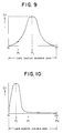
- the focus lens is controlled in movement relative to an object within a region between N (wide angle) and ⁇ (telephoto) so that the curve of evaluation data Dt is obtained as shown in Fig. 9.
- the focus lens is moved in a given direction so as to verify the direction in which the evaluation data Dt is maximized.
- the evaluation data Dt is being consecutively acquired.
- the focus lens is fine-tuned in movement toward the N or ⁇ setting.
- the focus lens is positioned at point p j where the maximum evaluation data Dt is obtained.
- the direction in which the auto focus operation starts i.e., the direction in which the direction determining operation starts, is illustratively set based on the focus position derived from the immediately preceding auto focus operation. That is, the initial direction of focus lens movement is not predetermined to be either in the N or in the ⁇ direction.
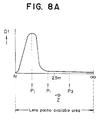
- the focus lens is driven up to the extreme point P 2 , where the lens changes its direction and starts moving in the N direction. It is only after past point P 1 that the appropriate evaluation data Dt is acquired. Thereafter, point P j is reached under mountain climbing control. That is, there occurs quite a redundant operation between points P 1 and P 2 .
- the curve of the accumulated data shown in Fig. 9 necessarily varies in peak position and shape depending on the distance to the object and on the nature thereof. Thus in an auto focus operation, the distance to the object always varies and the peak of the accumulated data curve varies accordingly. The varying peak position leads to focusing error.
- a second object such as a person or a car moves across between the object and the video camera.
- the evaluation data is accumulated with respect to the second object at the very movement the latter hides the original object when coming out in front of the video camera.
- the lens is automatically moved for focusing from point P 1 to point P 2 .
- the accumulated data drops abruptly as illustrated in Fig. 11.
- a drop in accumulated data under mountain climbing control causes the auto focus controller of the video camera to conclude that the lens position has gone past the peak of the accumulated data. Reversing the direction of lens movement, the auto focus controller erroneously judges that point P x immediately preceding the drop in the accumulated data is the just-focus position.
- One prior art detection method for the focus lens involves attaching a reflective film arrangement to a lens-mounted cylinder and providing a detecting means comprising light-emitting and light-receiving diodes, the reflective film arrangement giving reflected light whereby the lens position is detected.
- a method for effectively detecting the maximum positions of the lens is proposed by Japanese Patent Application No. 63-51293.
- the zoom lens is conventionally positioned in a simple manner illustratively involving the use of a resistor switch arrangement.
- the zoom lens requires relatively high levels of torque. Because the driving torque varies significantly from one driving unit to another, simply raising or lowering the DC voltage supply to the zoom ring motor is not sufficient to fine-tune the zoom lens movement while the lens movement speed is being adjusted. Where it is desired to move the zoom lens for a very short distance by lowering the DC voltage, one of two things may occur: the coefficient of mechanical static friction in the lens moving mechanism may be high enough to prevent the lens from moving at all, or the lens may move suddenly--and unpredictably--when the rising voltage reaches a certain critical level.
- the above impediment makes it impossible to improve the means of the video camera for searching the just-focus point in a narrow area in a fine-tuning manner during an auto focus operation within the macro region.
- the invention makes it possible to employ position detection signals that are the same for an automatically focused zoom lens at both edges of the macro region.
- the zoom lens may be driven upon power-up in the telephoto direction in order to detect at which edge of the macro region the zoom lens is currently located, the position detection signal then being acquired when the zoom lens leaves the macro edge area. This ensures verification of the lens position to prevent system error.
- a first macro region edge detection signal alone may be disconnected so as to prevent system error.
- a controller may intermittently supply driving signals to a zoom lens driving circuit at least near the just-focus point of an automatically focused zoom lens during a macro auto focus operation in the macro region for the purpose of fine-tuned search for the just-focus point of the lens.
- unavailability thereafter of appropriate focus control information for a predetermined period of time causes the controller of the camera to conclude that the just-focus point is not found in that direction and to change the lens in its moving direction accordingly.
- the lens is not moved all the way to the edge of the region. This improves the efficiency of the auto focus operation.
- specific frequency components of the video signal are successively accumulated as focus control information while the focus lens is being moved for auto focusing, the control information being referenced to drive the focus lens in the direction in which the accumulated data (i.e. control information) becomes maximized.
- This aspect of the invention is intended to prevent an abrupt drop in the successively accumulated data of the specific frequency components in the video signal from being used as part of the auto focus control information. Such sudden drops in the accumulated data occur when, illustratively, a person walks across between the video camera and its object during an auto focus operation.
- Fig. 2 is a block diagram depicting one embodiment of the auto focus control circuit in the video camera according to the invention.
- reference numeral 1 is a lens system wherein a focus lens is rotated by a driving motor 2 in arrowed directions A and B and is thereby moved in arrowed directions C and D for focus position control.
- This lens system is automatically focused under what is known as mountain climbing control based on a contrast detecting method (frequency separating method) to be described later.
- the focus lens is in focus at longer distances when driven in direction A (i.e., moved in direction C), and comes into focus at shorter distances when driven in direction B (i.e., moved in direction D).
- Reference numeral 3 is a CCD (charge coupled device) image pickup device that photographs an object via the lens system 1.
- the CCD image pickup device outputs the image signal to a signal processor 4.
- the signal processor 4 comprising a process circuit and a color encoder, generates a luminance signal and a chrominance signal based on the output signal from the CCD image pickup device 3.
- Band pass filters 5a and 5b are supplied with the luminance signal from the signal processor 4.
- the band pass filters 5a and 5b illustratively have center frequencies of 100 kHz and 500 kHz, respectively. These filters extract predetermined frequency components from the luminance signal supplied by the signal processor 4.
- the extracted frequency components are supplied via amplifiers to detectors 6a and 6b where the levels of the frequency components are detected.
- a switching circuit 7 determines, under control of an auto focus system controller (simply called the controller) 10, which of the two outputs of the detected frequency components is to be used, the frequency components having been extracted by the band pass filters 5a and 5b. For example, if the object of the camera is in high contrast against its background, the output from the band pass filter 5a is selected; if the object is in low contrast against its background, the output from the band pass filter 5b is selected.
- an auto focus system controller simply called the controller
- the digital output from the A/D converter 8 is supplied to an accumulator 9.
- the accumulator 9 is supplied with an accumulation area control signal from the controller 10.
- the level data of the predetermined frequency component, supplied from the A/D converter 8 after extraction from the luminance signal, is accumulated for a period of time designated by the accumulation area control signal. In a practical accumulating operation, the maximum value of one horizontal period may be illustratively accumulated for one field.
- the accumulated data is supplied as evaluation data Dt to the controller 10.
- the controller 10 uses the evaluation data Dt supplied, the controller 10 provides mountain climbing control over auto focus operations.
- the focus lens is driven from out-of-focus state through just-focus state to again out-of-focus state.
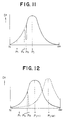
- the distribution of the spectrum components is measured along with their intensities.
- the spectrum components are on the low frequency side and their intensities are also low.
- the spectrum components are on the high frequency side and their intensities become high.
- the accumulated data provides various curves regarding various types of objects. Therefore, the lens is automatically focused when driven to point P j at which the accumulated data of the high-frequency components extracted from the video signal is maximized.
- the controller 10 has a software-based comparing means for comparing consecutively input and accumulated data so as to find the point at which the accumulated data Dt is maximized. Also contained in the controller 10 is a means for obtaining the rate of change of the accumulated data Dt with respect to the immediately preceding accumulated data Dt n-1 , the obtained rate of change being compared with a predetermined reference rate of change K.
- a focus lens motor driver 11 drives driving motors 2a and 2b in accordance with driving direction control signals S F and S B from the controller 10.
- a driving speed control signal S S is supplied to the focus lens motor driver 11 via a D/A converter 12.
- the signal S S causes the driver 11 to determine the lens driving speed.
- the driving direction control signals S F and S B as well as the driving speed control signal S S are generated under mountain climbing control.
- the driving direction control signal S F drives the lens in the telephoto ( ⁇ ) direction; the driving direction control signal S B drives the lens in the wide angle (N) direction.
- a focus lens position detector 13 detects the focus lens position as follows: A reflective film is illustratively formed on a predetermined area of the focus lens cylinder. Light-emitting diodes apply detecting light to the cylinder. A check is made to see if the position of the cylinder rotating in direction A or B is the one in which the reflected light is available. The detection signal is input to the controller 10 via an A/D converter 14.
- the position detector 13 detects two things: that the lens has reached its edge position (maximum wide angle position or maximum telephoto position), and that the lens has reached a 2.5-meter focus point.
- the controller 10 provides mountain climbing control based on the evaluation data Dt to automatically bring the focus lens into focus.
- the auto focus operation (under mountain climbing control) is attained in five modes of control: (1) driving start mode, (2) direction detecting mode, (3) focus point passing mode, (4) reverse mode, and (5) fine-tuning mode.
- the lens is first moved in a given direction in driving start mode (1).
- direction detecting mode (2) is selected.
- a direction determining operation is carried out in accordance with the evaluation data Dt, Dt ... being consecutively accumulated while the lens is being moved.
- focus point passing mode (3) the lens is moved in the determined direction while the evaluation data Dt is being detected. At this time, the consecutively acquired evaluation data Dt becomes greater as the lens approaches its just-focus point.
- the evaluation data Dt obtained past that point is lower than the immediately preceding evaluation data Dt.
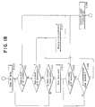
- an intermediate point detecting operation is carried out during the auto focus operation controlled by the controller 10, as described in the flowchart of Fig. 18.
- step F100 of Fig. 18 the controller 10 enters driving start mode (1) and outputs the driving speed control signal S S as well as the driving direction control signal S F or S B to drive the lens in one direction.
- step F101 the controller 10 first enters direction detecting mode (2) and performs a direction determining operation. That is, when the evaluation data Dt keeps increasing as the lens is moved, the controller 10 judges that the peak of the data exists on an extension of the current lens movement, and step F108 is reached. In step F108, the focus lens is brought to the just-focus point P j in modes (3) through (5). If the evaluation data Dt keeps decreasing as the lens is moved, step F102 is reached in which the controller 10 judges that the peak of the data exists in the reverse direction of the current lens movement.
- step F107 the controller 10 outputs the other driving direction control signal, S B or S F , to reverse the direction of lens movement.
- step F108 is reached in which the focus lens is brought as before to the just-focus point P j in modes (3) through (5).
- step F103 a check is made to see if the focus lens has reached the 2.5-meter focus point.
- step F104 is reached in which a built-in counter means starts counting time. This is typically the case with the example shown in Fig. 8 (A) or 8 (B) where the focus lens is moved in mode (1) from point P 1 in the arrowed direction Z.
- step F105 a check is made to see if the evaluation data Dt increases as the lens keeps moving in the current direction before time is up on the counter means. If the data Dt is found to be on the increase, step F108 is reached in which the focus lens is brought to the just-focus point P j in modes (3) through (5).
- step F107 is reached in which the direction of lens movement is reversed.
- step F106 the time required to move the lens from the 2.5-meter focus point to point P 3 is counted.
- the lens is moved in the current direction in step F106, up to point P 3 where time is up.
- the controller 10 judges that the lens is moving away from the just-focus point, and reverses the direction of lens movement accordingly in step F107.
- the lens is then driven in reverse and comes to a point where the evaluation data Dt is available, whereupon step F108 is reached and the operations of modes (3) through (5) are carried out.
- the focus lens is thus brought to the just-focus point P j .
- the video camera of this embodiment has no need for one of the hitherto-required redundant operations with the prior art: that its focus lens is to be moved in reverse direction in mode (1) all the way up to its maximum position even if that direction is on the opposite side of the just-focus point, and to come back thereto to complete the focusing operation.
- the intermediate point may alternatively be established somewhere other than the 2.5-meter focus point. All that is required is that the intermediate point be appropriate for the characteristics of a given video camera.
- the period of time counted starting from the 2.5-meter focus point may also be determined as needed in accordance with the characteristics of the implemented equipment in question.
- the time that elapses from the intermediate point on may be alternatively judged not by counting time but by physically detecting point P 3 .
- the controller 10 checks to see if any drop in the accumulate data is attributable to the lens actually passing the just-focus point under mountain climbing control in focus point passing mode (3).
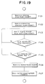
- controller 10 operates for auto focus operation control as depicted in the flowchart of Fig. 19.
- step F101 of Fig. 19 work in driving start mode (1) is carried out.
- step F102 work in direction detecting mode (2) is performed.
- step F103 focus point passing mode (3) is reached in which the lens is driven toward the peak of the accumulated data. Until the lens reaches the peak, a check is being made in step F104 to see if an accumulated value Dt n at a given point becomes smaller than the immediately preceding accumulated value Dt n-1 . If any drop in the accumulated data is detected, the controller 10 enters step F105 and checks to see if the drop is abrupt. It should be noted that reverse mode (4) is not immediately reached following step F104.
- the controller 10 has a predetermined reference rate of change K with which to compare the drop in the accumulated data.
- the controller 10 considers the drop to be an abrupt change in the accumulated data and concludes that the drop is not attributable to the lens having passed the peak point. In that case, the drop is ignored and the lens is allowed to keep moving in the same direction. These operations are carried out successively in steps F103, F104 and F105.
- the lens is driven from point P 1 in the ⁇ direction under auto focus control. If there is a sudden drop in the accumulated data during the lens movement, the drop is ignored and the lens keeps moving in the same direction.
- the abrupt drop at point P 2 does not cause the lens to be reversed in its movement and headed toward point P x in reverse mode (4); the lens keeps moving in the ⁇ direction toward the just-focus point P j following the panning.
- step F106 of Fig. 19 fine-tuning mode (5) is selected to bring the focus lens to the just-focus point P j .
- the above-described embodiment keeps its controller 10 from erroneously concluding that given an abruptly decreased accumulated value illustratively attributable to a person walking across in front of the lens or to a sudden panning, the value immediately preceding the drop is to be the peak.
- the focus lens does not stop at an out-of-focus point while being automatically focused.
- a reference rate of change K′ may be set up for comparison with (Dt n-1 /Dt n ), whereby a decision is made of the decrease in accumulated data.
- Many other methods and arrangements may also be provided to implement the same function.
- the reference level of the decrease in accumulated data i.e., the level at which all drops in the data are judged to be normal or abrupt, may be suitably established in accordance with the characteristics of the video camera implemented.
- Fig. 1 is a block diagram showing another embodiment of the auto focus control circuit in the video camera according to the invention.
- reference numeral 1 is a lens system wherein a focus lens and a zoom lens are rotated by driving motors 2a and 2b in arrowed directions A and B and are thereby moved in arrowed directions C and D for focus position control.
- the focus lens and the zoom lens are automatically focused, respectively, in the normal region and the macro region for normal and macro auto focus operations under mountain climbing control based on a contrast detecting method (frequency separating method) to be described later.
- the focus lens and zoom lens are in focus at longer distances when driven in direction A (i.e., moved in direction C), and come into focus at shorter distances when driven in direction B (i.e., moved in direction D).
- Reference numeral 3 is a CCD (charge coupled device) image pickup device that photographs an object via the lens system 1.
- the CCD image pickup device outputs the image signal to a signal processor 4.
- the signal processor 4 comprising a process circuit and a color encoder, generates a luminance signal and a chrominance signal based on the output signal from the CCD image pickup device 3.
- Band pass filters 5a and 5b are supplied with the luminance signal from the signal processor 4.
- the band pass filters 5a and 5b illustratively have center frequencies of 100 kHz and 500 kHz, respectively. These filters extract predetermined frequency components from the luminance signal supplied by the signal processor 4.
- the extracted frequency components are supplied via amplifiers to detectors 6a and 6b where the levels of the frequency components are detected.
- a switching circuit 7 determines, under control of an auto focus system controller (simply called the controller) 10, which of the two outputs of the detected frequency components is to be used, the frequency components having been extracted by the band pass filters 5a and 5b. For example, if the object of the camera is in high contrast against its background, the output from the band pass filter 5a is selected; if the object is in low contrast against its background, the output from the band pass filter 5b is selected.
- an auto focus system controller simply called the controller
- the digital output from the A/D converter 8 is supplied to an accumulator 9.
- the accumulator 9 is supplied with an accumulation area control signal from the controller 10.
- the level data of the predetermined frequency component, supplied from the A/D converter 8 after extraction from the luminance signal, is accumulated for a period of time designated by the accumulation area control signal. In a practical accumulating operation, the maximum value of one horizontal period may be illustratively accumulated for one field.
- the accumulated data is supplied as evaluation data Dt to the controller 10.
- the controller 10 uses the evaluation data Dt supplied, the controller 10 provides mountain climbing control over auto focus operations.
- the focus lens or zoom lens is driven from out-of-focus state through just-focus state to again out-of-focus state.
- the distribution of the spectrum components is measured along with their intensities.
- the spectrum components are on the low frequency side and their intensities are also low.
- the spectrum components are on the high frequency side and their intensities become high.
- auto focus control is effected by driving the lens in such a way that the accumulated data of the high-frequency components extracted from the video signal is maximized.
- the focus lens and the zoom lens are driven axially in the normal and macro regions, respectively, within the lens movement area (N ⁇ --> ⁇ ) as shown in Fig. 3.
- a search is made for a point FP at which the evaluation data Dt is maximized (mountain climbing control). This provides auto focus control over both regions.
- a focus lens motor driver 11a and a zoom lens motor driver 11b drive driving motors 2a and 2b, respectively, in accordance with driving direction control signals S F and S B from the controller 10.
- a driving speed control signal S s is supplied to the motor drivers 11a and 11b via a D/A converter 12.
- the signal S s causes the drivers 11a and 11b to determine the lens driving speed.
- the driving direction control signals S F and S B as well as the driving speed control signal S S are generated under mountain climbing control.
- the driving direction control signal S F drives the lens in the telephoto direction; the driving direction control signal S B drives the lens in the macro side direction.
- a focus lens position detector 13 detects the focus lens position as follows: A reflective film is illustratively formed on a predetermined area of the focus lens cylinder. Light-emitting diodes apply detecting light to the cylinder. The position of the focus lens is detected by checking to see if the lighted position coincides with the reflective film portion, i.e., if the position of the cylinder rotating in direction A or B is the one in which the reflected light is available. The detection signal is input to the controller 10 via an A/D converter 14.
- a zoom lens position detector 15 is constituted by three microswitches SW 1 through SW 3 .
- the zoom lens cylinder illustratively has suitable grooves corresponding to the microswitches SW 1 - SW 3 .
- the sliding member of each microswitch is turned on and off upon contact with the corresponding groove, allowing the zoom lens position to be detected.
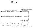
- the microswitches SW 1 - SW 3 are each turned on and off as shown in Fig. 4 with respect to the zoom lens positions from the telephoto setting T to the macro edge setting MCb.
- the on-off information from each of the microswitches SW 1 - SW 3 is illustratively weighted, as depicted in Fig.
- the weighted information is digitally coded by the A/D converter 16 into position detection signals representing the respective regions.
- the position detection signals position information codes
- the position detection signals are numbered (1) through (5) for explanatory purposes.
- a macro mode switch 18 is operated by the user to bring the controller 10 into macro mode in which a macro auto focus operation is carried out. Specifically, the zoom lens is driven under mountain climbing control and brought into focus regarding an object closer than that of the widest angle setting in normal mode.
- a power zoom switch 19 is operated by the user to drive the zoom lens as desired in normal mode. Specifically, this switch allows the user to drive the zoom lens at will (between telephoto and wide angle settings) while the focus lens is being automatically focused under mountain climbing control in normal mode between the maximum telephoto and maximum wide angle settings.
- the controller 10 provides mountain climbing control based on the evaluation data Dt to automatically bring the focus lens or the zoom lens into focus in the normal or macro region.
- the position detection signals (position information codes) from the zoom lens position detector 15 of this embodiment come in five types, (1) through (5), coded according to the on-off information from the microswitches SW 1 - SW 3 .
- the same position information code (4) is provided.
- the controller 10 must have means to determine whether the zoom lens is positioned in the area MCa or MCb.
- the above distinction between the two areas is required during the macro auto focus operation with the zoom lens positioned within the macro region.
- the zoom lens In an operation within the normal region (i.e., in normal mode), the zoom lens is kept from entering the macro region. It is only after the user has operated the macro mode switch 18 that the zoom lens enters the macro region. Control measures for keeping the zoom lens out of the macro region in normal mode will be described later.
- the zoom lens In macro mode, the zoom lens is normally positioned in the macro region. If the position information code (4) is obtained in this mode, the distinction between MCa and MCb is made by checking the direction of zoom lens movement. That is, the controller 10 is cognizant of the lens driving direction because the zoom lens is automatically focused with the driving direction control signals S F and S B as well as the driving speed control signal S S generated under mountain climbing control based on the evaluation data Dt. Thus when the driving direction control signal S F is output, the zoom lens is driven in the telephoto direction. If the position information code (4) is detected at this point, the zoom lens is judged to be positioned in the macro edge area MCa. Conversely, when the driving speed control signal S S is output, the zoom lens is driven in the maximum macro direction. The position information code (4) detected at this point is judged to indicate that the zoom lens is positioned in the macro edge area MCb.
- the controller 10 has software-based means (outlined below) to prevent erroneous operations in the above two cases.
- the controller 10 has driving means to drive the zoom lens in the telephoto direction if a macro edge area detection signal is obtained upon power-up.
- the controller 10 has control means to stop driving the zoom lens and place the video camera in normal mode if the position detection signal obtained when the zoom lens left the macro edge area after power-up indicates the normal region, the control means further bringing the zoom lens back to the initial position in effect upon power-up and placing the video camera in macro mode if the position detection signal indicates the macro region.
- the controller 10 also has driving means for driving the zoom lens in the macro direction if the macro mode switch 18 is operated.
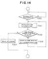
- the controller 10 has determining means for checking to see if the signal indicating an entry into the macro edge area by the zoom lens means that the detected entry is the first one into the macro edge area since the lens began moving in the macro direction. Furthermore, the controller 10 has cut-off means for cutting off macro edge detection information until the zoom lens leaves the macro edge area if the above determining means finds that the detected entry by the zoom lens into the macro edge area is the first one. These means are all constituted by software arrangements and provide the kinds of control illustrated in Figs. 13 and 14.
- step F100 power is applied.
- step F101 a check is made to see if the position information code detected by the zoom lens position detector 15 is numbered (4). If the code is any of (1), (2), (3) and (5), the zoom lens position is obtained unmodified, and there is no problem with subsequent operational control. If the position information code (4) is obtained in step F101, no meaningful distinction is made between the macro edge areas MCa and MCb. In that case, step F102 is reached in which the zoom lens is first driven in the telephoto direction. In step F103, a check is made to see if the zoom lens has left the macro edge area in question. With the lens having left the macro edge area, step F104 is reached in which the position information code is verified.
- step F105 is reached in which the zoom lens is stopped and the controller 10 enters normal mode for subsequent various kinds of control. This is the case where the zoom lens was positioned in the macro edge area MCa at the time of power-up. The position of MCa differs very little from the maximum wide angle position. Thus immediate, unmodified transition to normal mode poses no problem.
- step F106 is reached in which the zoom lens is driven in the opposite direction of step F102 for the same period of time thereof. This causes the zoom lens to return to its initial position upon power-up.
- the controller 10 recognizes the current position of the zoom lens as the macro edge area MCb, and provides macro mode control thereafter.
- the zoom lens is moved in the macro direction in step F201.
- the zoom lens is placed under mountain climbing control.
- the zoom lens enters the macro edge area MCa. This entry into the macro edge area by the zoom lens is verified when the position detection code (4) is obtained in step F202. In that case, the zoom lens is moved in the macro direction under control of the driving direction control signal S B .
- the lens position would be erroneously judged to be the macro edge area MCb.
- step F203 the detected information is cut off by the cut-off means for a predetermined period of time.
- the purpose of the cut-off is to keep the information from being used as various kinds of system control information by the controller 10.
- the cut-off period is set as long as is necessary for the zoom lens to pass the macro edge area MCa.
- step F204 is reached in which a macro auto focus operation is started under mountain climbing control.
- the three-microswitch detection arrangement that generates the signals of Fig. 4 provides accurate position detection in the manner described above. There is no need to develop a complicated detecting mechanism or to provide a large number of switches whereby all positions (areas) are to be detected using different position detection codes.
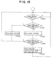
- step F300 of Fig. 15 the user operates the power zoom switch 19.
- step F301 a check is made to see if the user's operation is intended to move the zoom lens in the telephoto direction. If the user's operation is so intended, step F302 is reached.
- step F302 the controller 10 supplies the zoom lens motor driver 11b with the driving direction control signal S F and the appropriate driving speed control signal S S so that the zoom lens is moved in the telephoto direction.
- step F303 If it is found in step F301 that the user's operation is intended to move the zoom lens in the wide angle direction, step F303 is reached.
- the controller 10 supplies the zoom lens motor driver 11b with the driving direction control signal S B and the appropriate driving speed control signal S S so that the zoom lens is moved in the wide angle direction. If the zoom lens reaches the macro edge area during its movement and the position information code (4) is detected in step F304, the zoom lens is driven back in the telephoto direction in step F305 over a predetermined length and is thereupon brought to a stop.
- the auto focus operation comprises five modes of control: (1) driving start mode, (2) direction detecting mode, (3) focus point passing mode, (4) reverse mode, and (5) fine-tuning mode.
- the lens is initially located at point P 0 of Fig. 6.
- the evaluation data Dt is acquired successively.
- direction detecting mode (2) is selected. In this mode, whether or not the lens is moving toward the just-focus point P j is determined based on the evaluation data Dt, Dt ... being successively acquired during the lens movement. If it is judged that the just-focus point P j is not located on an extension of the current direction, the lens is reversed in its movement. In the case of Fig. 6, the lens is reversed to move in the direction B. Then focus point passing mode (3) is selected.
- the lens keeps moving in the direction B while the evaluation data Dt is being detected.
- the consecutively detected evaluation data Dt increases as the lens approaches the just-focus point P j .
- point P 1 that evaluation data Dt obtained at that point is lower than the immediately preceding evaluation data Dt. This drop in the evaluation data makes it possible to detect that the lens has passed the just-focus point.
- reverse mode (4) is selected and the lens is reversed in its movement (to move in the direction A). The lens is allowed to move back a little toward the just-focus point P j .
- fine-tuning mode (5) is selected in which the lens is fine-tuned in the directions A and B until the just-focus point P j , where the highest evaluation data Dt is acquired, is reached.
- the driving speed control signal S S is generated intermittently with a predetermined pulse width and supplied to the zoom lens motor driver 11b.
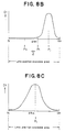
- the driving speed control signal S S is normally generated by the controller 10 as a DC signal of a predetermined constant voltage, as shown in Fig. 7 (A).
- the signal is supplied via the D/A converter 12 to the zoom lens motor driver 11b which in turn drives the zoom lens.
- the software-based means of the controller 10 are used illustratively to supply the driving speed control signal S S for two vertical synchronizing periods and to stop it for one vertical synchronizing period out of every three periods, as depicted in Fig. 7 (B).
- the driving speed control signal S S is supplied for one vertical synchronizing period and stopped for two vertical synchronizing periods out of every three, as shown in Fig. 7 (C). With the driving speed control signal S S thus generated intermittently, the zoom lens motor 2b is turned on and off to fine-tune the movement of the lens that requires relatively high levels of driving torque.
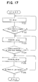
- the flowchart of Fig. 17 shows an example of intermittent generation of the driving speed control signal S S under mountain climbing control. It is assumed in the following description that the macro region starts at point P 2 in Fig. 6 and extends toward the N side.
- step F101 of Fig. 17 where the zoom lens is driven within the normal region the driving speed control signal S S is supplied in the form of the normal DC signal.
- the macro mode switch 18 is illustratively operated to initiate a macro auto focus operation
- the zoom lens reaches point P 2 .
- step F102 a check is made to see if the zoom lens has entered the macro region.
- step F103 is reached in which the controller 10 stops generating the driving speed control signal S S in one vertical synchronizing period out of every three. That is, the intermittent signal of Fig. 7 (B) is supplied to the zoom lens motor driver 11b. This makes it possible to fine-tune the zoom lens movement in the macro region.
- step F105 the controller 10 generates the driving speed control signal S S for one vertical synchronizing period out of every three. This step is required to perform fine-tuned zoom lens movement up to the just-focus point P j . That is, the intermittent signal of Fig. 7 (C) is supplied to the zoom lens motor driver 11b. This signal allows the zoom lens to be fine-tuned in its movement in fine-tuning mode (5) until the just-focus point is searched for and reached in step F106.
- the driving signal control signal S S is generated intermittently to drive the zoom lens. This makes it possible to establish the movement speed appropriate to the amount of movement while the signal voltage for providing a constant level of driving torque is maintained.
- the zoom lens is readily moved in a fine-tuned manner over a very short distance within the macro region (especially in fine-tuning mode (5)).
- the driving speed control signal S S is intermittently generated with a pulse width corresponding to appropriate vertical synchronizing periods.
- the pulse width for intermittent signal generation may be suitably set depending on the conditions unique to the implemented equipment.
- the pulse width instead of being established in two stages for intermittent signal generation, may be controlled in a larger number of stages.
- the driving speed control signal S S may be generated intermittently only after reverse mode (4) is selected for mountain climbing control.
- the intermittent signal generating scheme may also be applied to zoom lens moving speed control in normal mode. In some cases, this scheme may be applied to the focus lens.
- the video camera according to the invention has means to reverse the direction of the focus lens if appropriate evaluation data is not obtained within a certain period of time after an intermediate point is detected during focus lens movement in one direction.
- This feature eliminates the redundant operation of the focus lens moving away from the just-focus point all the way to the extreme of the current direction before heading back to the just-focus point during an auto focus operation. In this manner, an efficient auto focus operation is achieved.
- the video camera according to the invention has control means for not using a decrease in accumulated data as auto focus control information if that decrease is judged to be an abrupt drop from the accumulated data obtained in the immediately preceding focus lens position.
- This feature makes it possible to prevent the focus lens from being erroneously focused in such cases where some other object moves across between the video camera and its current object or where the video camera is abruptly panned from one object to another. In this manner, the photographing of high quality is always made available.
- the video camera according to the invention uses the same detection signal to detect both macro edge areas, and finds out in which of the two macro edge areas the zoom lens is located upon power-up or at the start of macro mode. In this manner, the use of only a small number of switching devices is sufficient to detect zoom lens positions, and system error is prevented regarding the distinction between the two macro edge areas in any of which the zoom lens may be positioned.
- the video camera according to the invention has the controller that intermittently supplies a lens driving signal to the zoom lens driving circuit at least close to the just-focus point in macro mode. This feature allows the zoom lens to be fine-tuned in its movement aimed at reaching the just-focus point. That is, the zoom lens is brought to the just-focus point more easily than ever before.
Landscapes
- Physics & Mathematics (AREA)
- General Physics & Mathematics (AREA)
- Optics & Photonics (AREA)
- Engineering & Computer Science (AREA)
- Multimedia (AREA)
- Signal Processing (AREA)
- Automatic Focus Adjustment (AREA)
Claims (14)
- Videokamera mit einer Zoomobjektiv-Funktionsfähigkeit, die umfasst:ein Fokussierungsobjektiv,ein Zoomobjektiv (1), das zwei Zoombereiche hat, wobei der eine Bereich ein Normal-Bereich ist, der von Fernaufnahme- (T-) bis zu Weitwinkel- (W-)Einstellungen reicht, und der andere Bereich ein Makro-Bereich (MC) ist, der Ränder (MCa, MCb) an den zwei jeweiligen Enden desselben hat,ein Positionsbestimmungsmittel (15, SW1-SW3), das auf eine Verschiebung des Zoomobjektivs anspricht und kodierte Daten erzeugt, die für die Position des Zoomobjektivs in den zwei Zoombereichen repräsentativ sind, wobei die kodierten Daten aus dem Positionsbestimmungsmittel (15, SW1-SW3) ein erster, gleicher Kode (4) sind, wenn das Zoomobjektiv (1) auf den einen oder den anderen der Ränder (MCa, MCb) des Makro-Bereichs (MC) eingestellt ist, und ein zweiter Kode (5) sind, der von dem ersten Kode verschieden ist, wenn das Zoomobjek-tiv auf eine aller Positionen zwischen den Rändern in dem Makro-Bereich eingestellt ist,eine Steuereinrichtung (10), die zum Bewirken einer Fo-kussierungssteuerung auf die kodierten Daten anspricht und ein Unterscheidungsmittel zum Bestimmen umfasst, an welchem der zwei Rander des Makro-Bereichs sich das Zoomobjektiv be-findet, undein Automatik-Fokussierungsmittel (11), das mit der Steuereinrichtung (10) zusammenarbeitet, zum Antreiben des Fokussierungsobjektivs, um die Videokamera in Verbindung mit der Position des Zoomobjektivs automatisch zu fokussieren, wenn sich dieses in dem normalen Bereich befindet,
dadurch gekennzeichnet, dass das Automatik-Fokussierungsmittel, das mit der Steuereinrichtung (10) zusammenarbeitet, in dem Makro-Modus zum Antreiben des Zoomobjektivs (1) betriebsfähig ist, eine automatische Fokussierung der Kamera zu bewirken, wenn sich diese in dem Makro-Bereich befindet,
wobei die Steuereinrichtung (10) dazu bestimmt ist, in dem Makro-Modus das Zoomobjektiv zu dem Ende (MCb) des Makro-Bereichs, das am weitesten von dem Normal-Bereich entfernt ist, zu treiben, um in dem Makro-Modus einen automatischen Fokussierungsvorgang an dem am weitesten entfernten Ende zu beginnen, wenn der am weitesten von dem normalen Bereich entfernte Rand (MCb) des Makro-Bereichs erfasst worden ist. - Videokamera nach Anspruch 1, wobei das Unterscheidungsmittel ein Mittel zum Bestimmen der Antriebsrichtung des Zoomobjektivs (1) umfasst.
- Videokamera nach Anspruch 1 oder 2, die ferner umfasst:einen Zoomobjektiv-Antrieb (2b) zum Bewegen des Zoomobjektivs zu der Seite der Fernaufnahme-Einstellungen im Falle der Erfasung eines Randsignals des Makro-Bereichs am Beginn eines Vorgangs.
- Videokamera nach Anspruch 3, wobei die Steuereinrichtung zum Stoppen des Antreibens des Zoomobjektivs (1) und Versetzen der Kamera in den Normal-Modus im Falle der Erfasung eines Normal-Bereichsignals nach Erfassung eines Randsignals des Makro-Bereichs (T) am Beginn des Vorgangs bestimmt ist.
- Videokamera nach Anspruch 3 oder 4, wobei die Steuereinrichtung zum Treiben des Zoomobjektivs in dessen Anfangsposition und Versetzen der Kamera in den Makro-Modus (MC) im Falle der Erfasung eines Makro-Bereichsignals nach Erfassung eines Randsignals des Makro-Bereichs am Beginn des Vorgangs bestimmt ist.
- Videokamera nach einem der Ansprüche 1 bis 5, wobeidas Automatik-Fokussierungsmittel zum Antreiben des Fokussierungsobjektivs in Verbindung mit dem Zoomobjektiv (1) bestimmt ist undein Antriebsmittel (2) zum Treiben des Zoomobjektivs zu der Makro- (MC-)Seite am Beginn eines automatischen Fokussierungsvorgangs in dem Makro-Bereich bestimmt ist.
- Videokamera nach Anspruch 6, wobeidie Steuereinrichtung (10) zum Erkennen bestimmt ist, ob eine erste Randerfassung des Makro-Bereichs nach dem Treiben des Zoomobjektivs zu der Makro-Seite im Falle der Erfassung eines Randsignals des Makro-Bereichs bewirkt ist oder nicht, undein Abschaltmittel zum Abschalten des Randsignals des Makro-Bereichs, wobei das Zoomobjektiv den Rand des Makro-Bereichs überläuft, bestimmt ist, wenn die Steuereinrichtung die erste Randerfassung des Makro-Bereichs erkennt.
- Videokamera nach einem der Ansprüche 1 bis 7, wobeidas Automatik-Fokussierungsmittel zum Antreiben des Zoomobjektivs (1) zur Fokussierungseinstellung in dem Makro-Bereich (MC) bestimmt ist.
- Videokamera nach Anspruch 8, wobeidas Antriebsmittel (11), das zwischen dem Zoomobjektiv (1) und dem Automatik-Fokussierungsmittel angeordnet ist, zum Erzeugen eines Treibersignals, das durch eine Vielzahl von Impulsen gebildet ist, bestimmt ist.
- Videokamera nach Anspruch 9, wobei das Antriebsmittel (11) das Treibersignal bis zumindest nahe dem Richtig-Fokussierungspunkt in dem Makro-Modus erzeugt
- Videokamera nach einem der Ansprüche 1 bis 10, die ferner mit einer automatischen Fokussierungsfunktion versehen ist, wobeidas Fokussierungsobjektiv (1) dazu bestimmt ist, durch ein Automatik-Fokussierungs-Steuersignal gesteuert zu werden, unddie Steuereinrichtung (10) zum Erzeugen des Automatik-Fokussierungs-Steuersignals bestimmt ist.
- Videokamera nach Anspruch 11, wobei das Automatik-Fokussierungs-Steuersignal durch Akkumulieren einer spezifischen Frequenzkomponente eines Eingangs-Videosignals berechnet wird.
- Videokamera nach Anspruch 12, die ferner umfasst:eine zweite Steuereinrichtung zum Nichtbeachten der akkumulierten Daten in einem Fall, in dem die akkumulierten Daten um einen vorbestimmten Wert niedriger als die unmittelbar vorhergehenden akkumulierten Daten sind.
- Videokamera nach einem der Ansprüche 11 bis 13 mit einer Automatik-Fokussierungsfunktion, wobeidas Fokussierungsobjektiv dazu bestimmt ist, durch ein Automatik-Fokussierungs-Steuersignal gesteuert zu werden,ein Erfassungsmittel (13) zum Erfassen der Position des Fokussierungsobjektivs zumindest bei einem Rand und im wesentlichen in dem Zentrum eines Bewegungsbereichs bestimmt ist unddie Steuereinrichtung (10) zum Umkehren der Richtung der Bewegung des Fokussierungsobjektivs in einem Fall bestimmt ist, in dem keine geeignete Fokussierungs-Steuerinformation innerhalb einer vorbestimmten Zeit nach Erfassung des angenäherten Zentrums des Fokussierungsobjektivs durch das Erfassungsmittel in einem automatischen Fokussierungsvorgang gewonnen ist, wobei das Fokussierungsobjektiv entsprechend in der anderen Richtung bewegt wird.
Applications Claiming Priority (12)
| Application Number | Priority Date | Filing Date | Title |
|---|---|---|---|
| JP10039090A JPH04404A (ja) | 1990-04-18 | 1990-04-18 | ビデオカメラ |
| JP100391/90 | 1990-04-18 | ||
| JP100389/90 | 1990-04-18 | ||
| JP10039190 | 1990-04-18 | ||
| JP10038990A JPH04421A (ja) | 1990-04-18 | 1990-04-18 | ビデオカメラ |
| JP100388/90 | 1990-04-18 | ||
| JP100390/90 | 1990-04-18 | ||
| JP10039090 | 1990-04-18 | ||
| JP10038890 | 1990-04-18 | ||
| JP10038990 | 1990-04-18 | ||
| JP2100388A JPH04403A (ja) | 1990-04-18 | 1990-04-18 | ビデオカメラ |
| JP2100391A JPH04981A (ja) | 1990-04-18 | 1990-04-18 | ビデオカメラ |
Publications (3)
| Publication Number | Publication Date |
|---|---|
| EP0455535A2 EP0455535A2 (de) | 1991-11-06 |
| EP0455535A3 EP0455535A3 (en) | 1993-06-30 |
| EP0455535B1 true EP0455535B1 (de) | 2000-06-28 |
Family
ID=27468821
Family Applications (1)
| Application Number | Title | Priority Date | Filing Date |
|---|---|---|---|
| EP91401038A Expired - Lifetime EP0455535B1 (de) | 1990-04-18 | 1991-04-18 | Videokamera mit Makromodus und automatischer Fokussierungseinstellung |
Country Status (4)
| Country | Link |
|---|---|
| US (1) | US5218444A (de) |
| EP (1) | EP0455535B1 (de) |
| KR (1) | KR100225544B1 (de) |
| DE (1) | DE69132267T2 (de) |
Families Citing this family (10)
| Publication number | Priority date | Publication date | Assignee | Title |
|---|---|---|---|---|
| JPH03230698A (ja) * | 1990-02-05 | 1991-10-14 | Mitsubishi Electric Corp | オートホワイトバランス調整装置 |
| EP0512430B1 (de) * | 1991-05-02 | 1997-09-03 | Canon Kabushiki Kaisha | Automatische Fokussierungsvorrichtung |
| US5678096A (en) * | 1992-02-25 | 1997-10-14 | Nikon Corporation | Camera with an interchangeable retractable lens barrel |
| US5345264A (en) * | 1992-02-27 | 1994-09-06 | Sanyo Electric Co., Ltd. | Video signal processing circuit for a video camera using a luminance signal |
| JP3302104B2 (ja) * | 1993-06-30 | 2002-07-15 | キヤノン株式会社 | 撮像装置 |
| JP3619537B2 (ja) * | 1994-03-28 | 2005-02-09 | 株式会社日立製作所 | ビデオカメラ、画像入力装置及び画像入力システム |
| US5663759A (en) * | 1996-06-10 | 1997-09-02 | Industrial Technology Research Institute | Feature processor for a digital camera |
| JP4214325B2 (ja) * | 1998-03-23 | 2009-01-28 | フジノン株式会社 | テレビカメラのレンズ操作装置 |
| US7598997B2 (en) * | 2004-01-14 | 2009-10-06 | Ricoh Company, Ltd. | Imaging apparatus and focus control method based on a number of automatic focus scan stages, and recording medium storing a program for executing such a method |
| JP5928062B2 (ja) * | 2012-03-26 | 2016-06-01 | セイコーエプソン株式会社 | 撮像装置及びその制御方法 |
Citations (2)
| Publication number | Priority date | Publication date | Assignee | Title |
|---|---|---|---|---|
| JPS6126015A (ja) * | 1984-07-16 | 1986-02-05 | Ricoh Co Ltd | オ−トフオ−カス方法 |
| JPH01132279A (ja) * | 1987-11-18 | 1989-05-24 | Sanyo Electric Co Ltd | オートフォーカスビデオカメラ |
Family Cites Families (10)
| Publication number | Priority date | Publication date | Assignee | Title |
|---|---|---|---|---|
| JPS57186872A (en) * | 1981-05-13 | 1982-11-17 | Hitachi Ltd | Auto-focusing device of video camera |
| JPS6329717A (ja) * | 1986-07-23 | 1988-02-08 | Minolta Camera Co Ltd | 焦点調節装置 |
| JPS6332510A (ja) * | 1986-07-26 | 1988-02-12 | Victor Co Of Japan Ltd | オ−トフオ−カス方式 |
| KR940011885B1 (ko) * | 1987-02-18 | 1994-12-27 | 상요덴기 가부시기가이샤 | 영상 신호에 기인해서 초점의 자동 정합을 행하는 오토포커스 회로 |
| US4899190A (en) * | 1987-05-31 | 1990-02-06 | Ricoh Company, Ltd. | Zooming optical system control device |
| JPH0212213A (ja) * | 1988-06-30 | 1990-01-17 | Asahi Optical Co Ltd | マクロ撮影・通常撮影機能付き電子制御カメラ |
| JPH01293771A (ja) * | 1988-05-20 | 1989-11-27 | Victor Co Of Japan Ltd | オートフォーカス方式 |
| US4920420A (en) * | 1988-11-10 | 1990-04-24 | Hitachi, Ltd. | Automatic focusing system |
| US4991944A (en) * | 1988-12-27 | 1991-02-12 | Matsushita Electric Industrial Co., Ltd. | Zoom lens driving apparatus |
| JPH0313073A (ja) * | 1989-06-09 | 1991-01-22 | Canon Inc | 自動焦点調節装置 |
-
1991
- 1991-04-10 US US07/683,559 patent/US5218444A/en not_active Expired - Lifetime
- 1991-04-18 DE DE69132267T patent/DE69132267T2/de not_active Expired - Lifetime
- 1991-04-18 KR KR1019910006190A patent/KR100225544B1/ko not_active Expired - Lifetime
- 1991-04-18 EP EP91401038A patent/EP0455535B1/de not_active Expired - Lifetime
Patent Citations (2)
| Publication number | Priority date | Publication date | Assignee | Title |
|---|---|---|---|---|
| JPS6126015A (ja) * | 1984-07-16 | 1986-02-05 | Ricoh Co Ltd | オ−トフオ−カス方法 |
| JPH01132279A (ja) * | 1987-11-18 | 1989-05-24 | Sanyo Electric Co Ltd | オートフォーカスビデオカメラ |
Also Published As
| Publication number | Publication date |
|---|---|
| EP0455535A3 (en) | 1993-06-30 |
| US5218444A (en) | 1993-06-08 |
| DE69132267D1 (de) | 2000-08-03 |
| EP0455535A2 (de) | 1991-11-06 |
| KR910019412A (ko) | 1991-11-30 |
| KR100225544B1 (ko) | 1999-10-15 |
| DE69132267T2 (de) | 2001-01-25 |
Similar Documents
| Publication | Publication Date | Title |
|---|---|---|
| US5434621A (en) | Object tracking method for automatic zooming and the apparatus therefor | |
| US7778539B2 (en) | Optical apparatus | |
| EP1921845B1 (de) | Objektivkontrollgerät und Schärfeeinstellungsverfahren für eine Bildaufnahmevorrichtung | |
| US7852398B2 (en) | Image-taking apparatus | |
| US8446519B2 (en) | Focus control apparatus and optical apparatus | |
| US5587842A (en) | Lens control system | |
| US7515200B2 (en) | Image sensing apparatus, focus adjustment method, and focus adjustment computer control program | |
| US7518807B2 (en) | Focus adjustment apparatus, image pickup apparatus, and control method | |
| US5005086A (en) | Focus control apparatus having two focusing speeds | |
| EP0455535B1 (de) | Videokamera mit Makromodus und automatischer Fokussierungseinstellung | |
| US7570298B2 (en) | Image-taking apparatus with first focus control such that in-focus position is searched for based on first signal and second focus control such that one of in-focus position and drive amount is determined based on second signal | |
| JP2941980B2 (ja) | 自動焦点調節装置 | |
| US5402175A (en) | Automatic focusing device wherein lens movement is controlled in accordance with lens hunting | |
| JPH05308557A (ja) | 自動合焦装置 | |
| JP3639823B2 (ja) | 自動焦点調節装置、その方法、及び制御プログラム | |
| JP2004093776A (ja) | カメラ | |
| JPH0614245A (ja) | ビデオカメラ | |
| US7710493B2 (en) | Image-pickup apparatus and focus control method | |
| JPH0443475B2 (de) | ||
| JP4241591B2 (ja) | レンズ鏡筒 | |
| JPH0886953A (ja) | 自動焦点整合装置 | |
| JPH049911A (ja) | レンズ位置制御装置 | |
| CA1339786C (en) | Focus control apparatus | |
| JPH04311908A (ja) | カメラシステム | |
| JPH08122839A (ja) | 自動焦点整合装置 |
Legal Events
| Date | Code | Title | Description |
|---|---|---|---|
| PUAI | Public reference made under article 153(3) epc to a published international application that has entered the european phase |
Free format text: ORIGINAL CODE: 0009012 |
|
| AK | Designated contracting states |
Kind code of ref document: A2 Designated state(s): DE FR GB |
|
| 17P | Request for examination filed |
Effective date: 19921111 |
|
| PUAL | Search report despatched |
Free format text: ORIGINAL CODE: 0009013 |
|
| AK | Designated contracting states |
Kind code of ref document: A3 Designated state(s): DE FR GB |
|
| R17P | Request for examination filed (corrected) |
Effective date: 19931210 |
|
| 17Q | First examination report despatched |
Effective date: 19950724 |
|
| GRAG | Despatch of communication of intention to grant |
Free format text: ORIGINAL CODE: EPIDOS AGRA |
|
| GRAG | Despatch of communication of intention to grant |
Free format text: ORIGINAL CODE: EPIDOS AGRA |
|
| GRAH | Despatch of communication of intention to grant a patent |
Free format text: ORIGINAL CODE: EPIDOS IGRA |
|
| GRAH | Despatch of communication of intention to grant a patent |
Free format text: ORIGINAL CODE: EPIDOS IGRA |
|
| GRAA | (expected) grant |
Free format text: ORIGINAL CODE: 0009210 |
|
| AK | Designated contracting states |
Kind code of ref document: B1 Designated state(s): DE FR GB |
|
| REF | Corresponds to: |
Ref document number: 69132267 Country of ref document: DE Date of ref document: 20000803 |
|
| ET | Fr: translation filed | ||
| PLBE | No opposition filed within time limit |
Free format text: ORIGINAL CODE: 0009261 |
|
| STAA | Information on the status of an ep patent application or granted ep patent |
Free format text: STATUS: NO OPPOSITION FILED WITHIN TIME LIMIT |
|
| 26N | No opposition filed | ||
| REG | Reference to a national code |
Ref country code: GB Ref legal event code: IF02 |
|
| REG | Reference to a national code |
Ref country code: GB Ref legal event code: 746 Effective date: 20091124 |
|
| PGFP | Annual fee paid to national office [announced via postgrant information from national office to epo] |
Ref country code: GB Payment date: 20100331 Year of fee payment: 20 |
|
| PGFP | Annual fee paid to national office [announced via postgrant information from national office to epo] |
Ref country code: FR Payment date: 20100506 Year of fee payment: 20 |
|
| PGFP | Annual fee paid to national office [announced via postgrant information from national office to epo] |
Ref country code: DE Payment date: 20100423 Year of fee payment: 20 |
|
| REG | Reference to a national code |
Ref country code: DE Ref legal event code: R071 Ref document number: 69132267 Country of ref document: DE |
|
| REG | Reference to a national code |
Ref country code: GB Ref legal event code: PE20 Expiry date: 20110417 |
|
| PG25 | Lapsed in a contracting state [announced via postgrant information from national office to epo] |
Ref country code: GB Free format text: LAPSE BECAUSE OF EXPIRATION OF PROTECTION Effective date: 20110417 |
|
| PG25 | Lapsed in a contracting state [announced via postgrant information from national office to epo] |
Ref country code: DE Free format text: LAPSE BECAUSE OF EXPIRATION OF PROTECTION Effective date: 20110418 |