EP0452548B1 - Träger einer Fahrzeug-Aufbaustruktur - Google Patents
Träger einer Fahrzeug-Aufbaustruktur Download PDFInfo
- Publication number
- EP0452548B1 EP0452548B1 EP90122467A EP90122467A EP0452548B1 EP 0452548 B1 EP0452548 B1 EP 0452548B1 EP 90122467 A EP90122467 A EP 90122467A EP 90122467 A EP90122467 A EP 90122467A EP 0452548 B1 EP0452548 B1 EP 0452548B1
- Authority
- EP
- European Patent Office
- Prior art keywords
- section
- hollow profile
- tubular section
- support according
- sections
- Prior art date
- Legal status (The legal status is an assumption and is not a legal conclusion. Google has not performed a legal analysis and makes no representation as to the accuracy of the status listed.)
- Expired - Lifetime
Links
Images

Classifications
-
- B—PERFORMING OPERATIONS; TRANSPORTING
- B62—LAND VEHICLES FOR TRAVELLING OTHERWISE THAN ON RAILS
- B62D—MOTOR VEHICLES; TRAILERS
- B62D29/00—Superstructures, understructures, or sub-units thereof, characterised by the material thereof
- B62D29/008—Superstructures, understructures, or sub-units thereof, characterised by the material thereof predominantly of light alloys, e.g. extruded
-
- E—FIXED CONSTRUCTIONS
- E04—BUILDING
- E04C—STRUCTURAL ELEMENTS; BUILDING MATERIALS
- E04C3/00—Structural elongated elements designed for load-supporting
- E04C3/02—Joists; Girders, trusses, or trusslike structures, e.g. prefabricated; Lintels; Transoms; Braces
- E04C3/04—Joists; Girders, trusses, or trusslike structures, e.g. prefabricated; Lintels; Transoms; Braces of metal
- E04C3/06—Joists; Girders, trusses, or trusslike structures, e.g. prefabricated; Lintels; Transoms; Braces of metal with substantially solid, i.e. unapertured, web
-
- E—FIXED CONSTRUCTIONS
- E04—BUILDING
- E04C—STRUCTURAL ELEMENTS; BUILDING MATERIALS
- E04C3/00—Structural elongated elements designed for load-supporting
- E04C3/02—Joists; Girders, trusses, or trusslike structures, e.g. prefabricated; Lintels; Transoms; Braces
- E04C3/04—Joists; Girders, trusses, or trusslike structures, e.g. prefabricated; Lintels; Transoms; Braces of metal
- E04C2003/0404—Joists; Girders, trusses, or trusslike structures, e.g. prefabricated; Lintels; Transoms; Braces of metal beams, girders, or joists characterised by cross-sectional aspects
- E04C2003/0408—Joists; Girders, trusses, or trusslike structures, e.g. prefabricated; Lintels; Transoms; Braces of metal beams, girders, or joists characterised by cross-sectional aspects characterised by assembly or the cross-section
- E04C2003/0421—Joists; Girders, trusses, or trusslike structures, e.g. prefabricated; Lintels; Transoms; Braces of metal beams, girders, or joists characterised by cross-sectional aspects characterised by assembly or the cross-section comprising one single unitary part
-
- E—FIXED CONSTRUCTIONS
- E04—BUILDING
- E04C—STRUCTURAL ELEMENTS; BUILDING MATERIALS
- E04C3/00—Structural elongated elements designed for load-supporting
- E04C3/02—Joists; Girders, trusses, or trusslike structures, e.g. prefabricated; Lintels; Transoms; Braces
- E04C3/04—Joists; Girders, trusses, or trusslike structures, e.g. prefabricated; Lintels; Transoms; Braces of metal
- E04C2003/0404—Joists; Girders, trusses, or trusslike structures, e.g. prefabricated; Lintels; Transoms; Braces of metal beams, girders, or joists characterised by cross-sectional aspects
- E04C2003/0426—Joists; Girders, trusses, or trusslike structures, e.g. prefabricated; Lintels; Transoms; Braces of metal beams, girders, or joists characterised by cross-sectional aspects characterised by material distribution in cross section
- E04C2003/043—Joists; Girders, trusses, or trusslike structures, e.g. prefabricated; Lintels; Transoms; Braces of metal beams, girders, or joists characterised by cross-sectional aspects characterised by material distribution in cross section the hollow cross-section comprising at least one enclosed cavity
-
- E—FIXED CONSTRUCTIONS
- E04—BUILDING
- E04C—STRUCTURAL ELEMENTS; BUILDING MATERIALS
- E04C3/00—Structural elongated elements designed for load-supporting
- E04C3/02—Joists; Girders, trusses, or trusslike structures, e.g. prefabricated; Lintels; Transoms; Braces
- E04C3/04—Joists; Girders, trusses, or trusslike structures, e.g. prefabricated; Lintels; Transoms; Braces of metal
- E04C2003/0404—Joists; Girders, trusses, or trusslike structures, e.g. prefabricated; Lintels; Transoms; Braces of metal beams, girders, or joists characterised by cross-sectional aspects
- E04C2003/0443—Joists; Girders, trusses, or trusslike structures, e.g. prefabricated; Lintels; Transoms; Braces of metal beams, girders, or joists characterised by cross-sectional aspects characterised by substantial shape of the cross-section
- E04C2003/0447—Joists; Girders, trusses, or trusslike structures, e.g. prefabricated; Lintels; Transoms; Braces of metal beams, girders, or joists characterised by cross-sectional aspects characterised by substantial shape of the cross-section circular- or oval-shaped
-
- E—FIXED CONSTRUCTIONS
- E04—BUILDING
- E04C—STRUCTURAL ELEMENTS; BUILDING MATERIALS
- E04C3/00—Structural elongated elements designed for load-supporting
- E04C3/02—Joists; Girders, trusses, or trusslike structures, e.g. prefabricated; Lintels; Transoms; Braces
- E04C3/04—Joists; Girders, trusses, or trusslike structures, e.g. prefabricated; Lintels; Transoms; Braces of metal
- E04C2003/0404—Joists; Girders, trusses, or trusslike structures, e.g. prefabricated; Lintels; Transoms; Braces of metal beams, girders, or joists characterised by cross-sectional aspects
- E04C2003/0443—Joists; Girders, trusses, or trusslike structures, e.g. prefabricated; Lintels; Transoms; Braces of metal beams, girders, or joists characterised by cross-sectional aspects characterised by substantial shape of the cross-section
- E04C2003/0465—Joists; Girders, trusses, or trusslike structures, e.g. prefabricated; Lintels; Transoms; Braces of metal beams, girders, or joists characterised by cross-sectional aspects characterised by substantial shape of the cross-section square- or rectangular-shaped
Definitions
- the invention relates to a carrier for a vehicle body structure according to the preamble of claim 1.
- EP-PS 0 146 716 shows a structure for a passenger car, the carrier of which is formed by box-shaped hollow profiles made of light metal.
- the hollow profiles are manufactured using the extrusion process.
- the object of the invention is to design a carrier of a body structure, in particular a longitudinal member arranged adjacent to a vehicle end region, in such a way that, on the one hand, it has a high energy absorption capacity in the event of an impact impact and, on the other hand, an impact damper of a bumper arrangement can be connected to the longitudinal member in a space-saving manner.
- the central tube section accommodates an impact damper in a simple, space-saving manner in the side member and that the central tube section and the two outer, preferably approximately square, hollow profile sections achieve good buckling behavior of the side member . In this way, a high energy absorption can be achieved in the event of an impact.
- each hollow profile section and the pipe section which are oriented at less than 45% to a horizontal auxiliary plane, ensure a functional folding of the side member in the event of an impact impact. Due to the preferred continuous tapering of the two lateral boundary edges of the side member below, the side members can be easily inserted from above into a cast iron node element surrounding them.
- the impact absorber inserted in the central pipe section runs at a small radial distance from the outer pipe section. In the event of an oblique impact on the side member, the impact damper is guided through the pipe section.
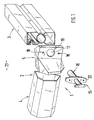
- FIG. 1 shows a front end area 1 of a body structure 2 of a passenger car, which in the area shown consists of a side member 3 and a cross member 4.
- the longitudinal beam 3 and the cross beam 4 are formed by a hollow profile made of light metal (aluminum, aluminum alloy, magnesium or the like) produced by the extrusion process and are connected to one another via a node element 5.
- the node element 5 is formed, for example, by a casting which is made of light metal (aluminum, aluminum alloy, magnesium or the like).
- the node element 5 encloses end regions 6, 7 of the inserted longitudinal member 3 and the cross member 4.
- the node element 5 is additionally connected to the carriers via a mechanical connection (screws, rivets or the like), by gluing or a thermal connection (welding) 3, 4 connected.
- a high energy absorption of the side member 3 in the event of an impact and a space-saving connection of a bumper arrangement to the side member 3 is achieved in that the side member 3 consists of a central tube section 8 and two outer hollow profile sections 9, 10 arranged on opposite sides of the pipe section 8, the hollow profile sections 9, 10 being closed off from the pipe section 8 via obliquely extending webs 11, 12, 13, 14. 3, the hollow profile sections 9, 10 are arranged below and above the central tube section 8.
- the pipe section 8 has a circular cross section and is dimensioned such that an impact damper 15 with a seat can be accommodated in sections within the pipe section 8.
- a cylindrical section 16 of the impact damper 15 is inserted through an opening 17 of the node element 5 into the tube section 8 of the side member 3 and is held in position on the node element 5 by means of fastening elements (e.g. screws) which are not shown in detail.
- the opening 17 and the threaded bores 18 are provided on a vertical wall 19 of the node element 5, a holding plate 20 of the impact damper 15 abutting on the outside of the vertical wall 19.
- the bumper device connected to the impact damper 15 is not shown in detail.
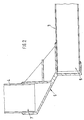
- each hollow profile section 9 and 10 run approximately at right angles to one another and at an angle ⁇ of approximately 45 ° to a horizontal auxiliary plane A-A.
- the two outer hollow profile sections 9, 10 are preferably approximately square, but they can also have a rectangular cross section.
- the outer hollow profile sections 9, 10 have a slightly larger width than the central tube section 8, i.e. the hollow profile sections 9, 10 protrude beyond the tube section 8 on both transverse sides.
- the lateral boundary edges 21, 22 of the longitudinal beam 3 taper downward (according to FIG. 3) continuously, namely from the width B1 to the width B2. However, there is also the possibility that the two boundary edges 21, 22 are aligned parallel to one another.
- a continuous undercut longitudinal groove 24 into which threaded plates (not shown locally) for fastening units or the like can be inserted. All wall sections of the longitudinal beam 3 produced in the extrusion process have a constant material thickness, which is dependent on the required energy consumption and the extrusion possibilities.
Landscapes
- Engineering & Computer Science (AREA)
- Architecture (AREA)
- Structural Engineering (AREA)
- Chemical & Material Sciences (AREA)
- Combustion & Propulsion (AREA)
- Transportation (AREA)
- Mechanical Engineering (AREA)
- Civil Engineering (AREA)
- Body Structure For Vehicles (AREA)
- Vibration Dampers (AREA)
Description
- Die Erfindung betrifft einen Träger für eine Fahrzeug- Aufbaustruktur gemäß dem Oberbegriff des Patentanspruchs 1.
- Aus der EP-PS 0 146 716 geht eine Aufbaustruktur für einen Personenwagen hervor, dessen Träger durch kastenförmige Hohlprofile aus Leichtmetall gebildet werden. Die Hohlprofile sind im Strangpreßverfahren hergestellt.
- Aufgabe der Erfindung ist es, einen Träger einer Aufbaustruktur, insbesondere einen benachbart eines Fahrzeugendbereiches angeordneten Längsträger so auszugestalten, daß er einerseits ein hohes Energieaufnahmevermögen bei einem Aufprallstoß aufweist und daß andererseits ein Pralldämpfer einer Stoßfängeranordnung in raumsparender Weise an den Längsträger anschließbar ist.
- Erfindungsgemäß wird diese Aufgabe durch die kennzeichnenden Merkmale des Anspruchs 1 gelöst. Weitere, die Erfindung in vorteilhafter Weise ausgestaltende Merkmale enthalten die Unteransprüche.
- Die mit der Erfindung hauptsächlich erzielten Vorteile sind darin zu sehen, daß durch den zentralen Rohrabschnitt ein Pralldämpfer in einfacher, raumsparender Weise im Längsträger aufgenommen ist und daß durch den zentralen Rohrabschnitt und die beiden äußeren, vorzugsweise etwa quadratischen Hohlprofilabschnitte ein gutes Faltenbeulverhalten des Längsträgers erreicht wird. Somit läßt sich bei einem Aufprallstoß eine hohe Energieaufnahme realisieren.
- Durch die vorzugsweise etwa rechtwinkelig zueinander angeordneten Stege zwischen jedem Hohlprofilabschnitt und dem Rohrabschnitt, die etwa unter 45 % zu einer horizontalen Hilfsebene ausgerichtet sind, wird ein funktionsgerechtes Zusammenfalten des Längsträgers bei einem Aufprallstoß gewährleistet. Durch die bevorzugte kontinuierliche Verjüngung der beiden seitlichen Begrenzungskanten des Längsträgers nach unten hin können die Längsträger in einfacher Weise von oben in ein sie umgebendes Knotenelement aus Guß eingesetzt werden.
- Der in den zentralen Rohrabschnitt eingesetzte Pralldämpfer verläuft mit geringem radialen Abstand zum außenliegenden Rohrabschnitt. Bei einem Schrägaufprall auf den Längsträger erfolgt somit eine Führung des Pralldämpfers durch den Rohrabschnitt.
- Ein Ausführungsbeispiel der Erfindung ist in der Zeichnung dargestellt und wird im folgenden näher beschrieben.
- Es zeigt:
- Fig. 1
- in perspektivischer Darstellung einen Endbereich einer Aufbaustruktur eines Personenwagens mit einem Längsträger,
- Fig. 2
- einen Horizontalschnitt durch die endseitige Aufbaustruktur,
- Fig. 3
- einen Vertikalschnitt durch den Längsträger der Aufbaustruktur.
- In Fig. 1 ist ein vorderer Endbereich 1 einer Aufbaustruktur 2 eines Personenwagens gezeigt, der im dargestellten Bereich aus einem Längsträger 3 und einem Querträger 4 besteht. Der Längsträger 3 und der Querträger 4 werden durch ein im Strangpreßverfahren hergestelltes Hohlprofil aus Leichtmetall (Aluminium, Aluminiumlegierung, Magnesium oder dgl.) gebildet und sind über ein Knotenelement 5 miteinander verbunden.
- Das Knotenelement 5 wird beispielsweise durch ein Gußteil gebildet, das aus Leichtmetall (Aluminium, Aluminiumlegierung, Magnesium oder dgl.) gefertigt ist.
- Gemäß Fig. 2 umschließt das Knotenelement 5 Endbereiche 6, 7 des eingelegten Längsträgers 3 sowie des Querträgers 4. Das Knotenelement 5 ist zusätzlich über eine mechanische Verbindung (Schrauben, Nieten oder dgl), durch Kleben oder eine thermische Verbindung (Schweißen) mit den Trägern 3, 4 verbunden.
- Eine hohe Energieaufnahme des Längsträgers 3 bei einem Aufprallstoß und ein raumsparender Anschluß einer Stoßfängeranordnung an den Längsträger 3 wird dadurch erzielt, daß der Längsträger 3 aus einem zentralen Rohrabschnitt 8 und zwei an gegenüberliegenden Seiten des Rohrabschnittes 8 angeordneten äußeren Hohlprofilabschnitten 9, 10 besteht, wobei die Hohlprofilabschnitte 9, 10 über schräg verlaufende Stege 11, 12, 13, 14 an den Rohrabschnitt 8 abgeschlossen sind. Gemäß Fig. 3 sind die Hohlprofilabschnitte 9, 10 unterhalb und oberhalb des zentralen Rohrabschnittes 8 angeordnet.
- Der Rohrabschnitt 8 weist einen kreisförmigen Querschnitt auf und ist so dimensioniert, daß ein Pralldämpfer 15 mit Spielsitz abschnittsweise innerhalb des Rohrabschnittes 8 aufgenommen werden kann. Ein zylindrischer Abschnitt 16 des Pralldämpfers 15 wird durch eine Öffnung 17 des Knotenelementes 5 in den Rohrabschnitt 8 des Längsträgers 3 eingeschoben und ist am Knotenelement 5 unter Vermittlung von nicht näher dargestellten Befestigungselementen (z.B. Schrauben) in Lage gehalten. Die Öffnung 17 und die Gewindebohrungen 18 sind an einer vertikalen Wand 19 des Knotenelementes 5 vorgesehen, wobei an der Außenseite der vertikalen Wand 19 eine Halteplatte 20 des Pralldämpfers 15 anliegt. Die mit dem Pralldämpfer 15 verbundene Stoßfängervorrichtung ist nicht näher dargestellt.
- Die beiden Stege 11, 12 bzw. 13, 14 jedes Hohlprofilabschnittes 9 bzw. 10 verlaufen etwa rechtwinkelig zueinander und unter einem Winkel α von etwa 45° zu einer horizontalen Hilfsebene A-A.
- Eine ideelle Verlängerung aller Stege 11, 12, 13, 14 führt durch den Mittelpunkt M1 des zentralen Rohrabschnittes 8.
- Die beiden äußeren Hohlprofilabschnitte 9, 10 sind -im Querschnitt gesehenvorzugsweise annähernd quadratisch ausgebildet, sie können aber auch einen rechteckigen Querschnitt aufweisen. Entsprechend Fig. 3 weisen die äußeren Hohlprofilabschnitte 9, 10 eine etwas größere Breite auf als der zentrale Rohrabschnitt 8, d.h., die Hohlprofilabschnitte 9, 10 überragen den Rohrabschnitt 8 zu beiden Querseiten hin.
- Die seitlichen Begrenzungskanten 21, 22 des Längsträgers 3 verjüngen sich (gemäß Fig. 3) nach unten hin kontinuierlich und zwar von der Breite B1 auf die Breite B2. Es besteht jedoch auch die Möglichkeit, daß die beiden Begrenzungskanten 21, 22 parallel zueinander ausgerichtet sind.
- Am oberen Hohlprofilabschnitt 9 ist auf der einem Motorraum 23 zugekehrten Seite eine durchgehende hinterschnittene Längsnut 24 vorgesehen, in die örtlich nicht gezeigte Gewindeplatten zum Befestigen von Aggregaten oder dgl. einsetzbar sind. Sämtliche Wandabschnitte des im Strangpreßverfahren hergestellten Längsträgers 3 weisen eine gleichbleibende Materialdicke auf, die abhängig von der erforderlichen Energieaufnahme und den strangpreßtechnischen Möglichkeiten ist.
Claims (7)
- Träger für eine Fahrzeug-Aufbaustruktur (2), der durch ein aus Leichtmetall hergestelltes Strangpreßprofil gebildet wird, das, in eingebautem Zustand in Vertikalrichtung gesehen, mehrere Hohlprofilabschnitte aufweist und der aus einem zentralen Rohrabschnitt (8) und zwei an gegenüberliegenden Seiten des Rohrabschnittes (8) angeordneten, äußeren Hohlprofilabschnitten (9, 10) besteht, dadurch gekennzeichnet, daß der zentrale Rohrabschnitt einen Kreisförmigen Querschnitt hat, wobei in den zentralen Rohrabschnitt (8) ein Pralldämpfer (15) einer Stroßfängeranordnung mit Spielsitz eingesetzt ist und daß jeder Hohlprofilabschnitt (9, 10) über zwei schräg verlaufende Stege (11,12, 13, 14) an den Rohrabschnitt (8) angeschlossen ist, dergestalt, daß jeder Steg (11, 12, 13, 14) unter einem Winkel α von etwa 45° zu einer horizontalen Hilfsebene (A-A) verläuft und daß eine ideelle Verlängerung jedes Steges (11, 12, 13, 14) den Mittelpunkt (M1) des Rohrabschnittes (8) schneidet.
- Träger nach Anspruch 1, dadurch gekennzeichnet, daß die beiden Stege (11, 12 bzw. 13, 14) jedes Hohlprofilabschnittes (9, 10) etwa rechtwinklig zueinander verlaufen.
- Träger nach Ansruch 1, dadurch gekennzeichnet, daß die beiden Hohlprofilabschnitte (9, 10) vorzugsweise einen etwa quadratischen Querschnitt aufweisen.
- Träger nach Anspruch 1, dadurch gekennzeichnet, daß alle Wandabschnitte des Strangpreßprofils eine gleichbleibende Materialdicke aufweisen.
- Träger nach Anspruch 1, dadurch gekennzeichnet, daß die beiden äußeren Hohlprofilabschnitte (9, 10) eine größere Breite aufweisen als der zentrale Rohrabschnitt (8).
- Träger nach Anspruch 1, dadurch gekennzeichnet, daß ein zylindrischer Abschnitt (16) des Pralldämpfers mit Spielsitz innerhalb des Rohrabschnittes (8) aufgenommen wird.
- Träger nach Anspruch 1, dadurch gekennzeichnet, daß sich die Querschnitte der äußeren Hohlprofilabschnitte nach unten hin Kontinuierlich verjüngen.
Applications Claiming Priority (2)
| Application Number | Priority Date | Filing Date | Title |
|---|---|---|---|
| DE4009401A DE4009401A1 (de) | 1990-03-23 | 1990-03-23 | Traeger, insbesondere laengstraeger einer fahrzeug-aufbaustruktur |
| DE4009401 | 1990-03-23 |
Publications (3)
| Publication Number | Publication Date |
|---|---|
| EP0452548A2 EP0452548A2 (de) | 1991-10-23 |
| EP0452548A3 EP0452548A3 (en) | 1991-12-18 |
| EP0452548B1 true EP0452548B1 (de) | 1994-01-19 |
Family
ID=6402930
Family Applications (1)
| Application Number | Title | Priority Date | Filing Date |
|---|---|---|---|
| EP90122467A Expired - Lifetime EP0452548B1 (de) | 1990-03-23 | 1990-11-26 | Träger einer Fahrzeug-Aufbaustruktur |
Country Status (5)
| Country | Link |
|---|---|
| US (1) | US5085485A (de) |
| EP (1) | EP0452548B1 (de) |
| JP (1) | JPH04221275A (de) |
| DE (2) | DE4009401A1 (de) |
| ES (1) | ES2048392T3 (de) |
Families Citing this family (64)
| Publication number | Priority date | Publication date | Assignee | Title |
|---|---|---|---|---|
| CH682993A5 (de) * | 1990-07-06 | 1993-12-31 | Alusuisse Lonza Services Ag | Wagenkastenaufbau für Schienenfahrzeuge. |
| US5371988A (en) * | 1990-11-28 | 1994-12-13 | Hannes; Paul | Modular building system and frame members |
| JPH06503782A (ja) * | 1990-12-20 | 1994-04-28 | アウディ アクチェンゲゼルシャフト | 自動車ボディの構材結合、特に縦構材結合、およびアルミニウム構材の交換方法 |
| DE59102670D1 (de) * | 1990-12-20 | 1994-09-29 | Audi Ag | Gussteil für eine fahrzeugkarosserie. |
| DE4128730A1 (de) * | 1991-08-29 | 1993-03-04 | Konrad Steffinger | Rahmen fuer ein landwirtschaftliches anhaengerfahrzeug |
| NO173537C (no) * | 1991-09-06 | 1993-12-29 | Norsk Hydro As | Forsterkningsbjelke og kjoeretoeydoer med bjelken |
| DE4205591A1 (de) * | 1992-02-24 | 1993-08-26 | Bayerische Motoren Werke Ag | Fahrzeugkarosserie |
| US5320403A (en) * | 1992-04-29 | 1994-06-14 | Ford Motor Company | Space frame torque box |
| DE9217503U1 (de) * | 1992-12-22 | 1993-08-05 | Bgh -Service Berghauer Gmbh, 82538 Geretsried | Grundeinheit für ein Kraftfahrzeug |
| US5577793A (en) * | 1993-04-21 | 1996-11-26 | Kobasic; Richard A. | Multipurpose highway vehicle |
| DE4322717C2 (de) * | 1993-07-08 | 2003-02-13 | Daimler Chrysler Ag | Rahmen für Fahrzeuge |
| US5431445A (en) * | 1994-11-28 | 1995-07-11 | Ford Motor Company | Asymmetrical beam structure for a vehicle |
| US5580120A (en) * | 1995-02-23 | 1996-12-03 | Mascotech Tubular Products, Inc. | Vehicle door intrusion beam |
| US5785376A (en) * | 1995-06-21 | 1998-07-28 | Mascotech Tubular Products, Inc. | Vehicle door beam |
| DE19538456A1 (de) * | 1995-10-16 | 1997-04-17 | Bayerische Motoren Werke Ag | Bodengruppe für ein Kraftfahrzeug |
| DE19538457A1 (de) * | 1995-10-16 | 1997-04-17 | Bayerische Motoren Werke Ag | Mehrkammerprofil |
| KR100204994B1 (ko) * | 1995-11-23 | 1999-06-15 | 정몽규 | 신장가능한 도어 임팩트 빔 |
| DE19547241A1 (de) * | 1995-12-18 | 1997-06-19 | Bayerische Motoren Werke Ag | Trägeranordnung |
| DE19604942C2 (de) * | 1996-02-10 | 2002-09-12 | Daimler Chrysler Ag | Fahrwerksträger |
| ZA973413B (en) * | 1996-04-30 | 1998-10-21 | Autokinetics Inc | Modular vehicle frame |
| DE19618258A1 (de) * | 1996-05-07 | 1997-11-13 | Bayerische Motoren Werke Ag | Rahmen |
| DE19633910A1 (de) * | 1996-08-22 | 1998-02-26 | Bayerische Motoren Werke Ag | Rahmen für ein Fahrzeug |
| DE29615364U1 (de) * | 1996-09-04 | 1996-11-07 | Delphi Automotive Systems Deutschland GmbH, 42369 Wuppertal | Kraftfahrzeugkarosserie |
| DE19637242A1 (de) * | 1996-09-13 | 1998-03-19 | Bayerische Motoren Werke Ag | Träger für ein Kraftfahrzeug |
| DE19637241A1 (de) * | 1996-09-13 | 1998-03-19 | Bayerische Motoren Werke Ag | Träger für ein Kraftfahrzeug |
| DE19733191A1 (de) * | 1997-07-31 | 1999-02-18 | Porsche Ag | Querträger für Fahrzeuge |
| US6250711B1 (en) * | 1998-07-31 | 2001-06-26 | Toyota Jidosha Kabushiki Kaisha | Energy absorber securing structure and method |
| DE19843025C1 (de) * | 1998-09-19 | 2000-04-20 | Daimler Chrysler Ag | Trennanordnung für eine selbsttragende Karosserie |
| JP3532775B2 (ja) | 1998-10-15 | 2004-05-31 | 本田技研工業株式会社 | 自動車用押し出し材フレーム結合構造 |
| JP3498614B2 (ja) * | 1999-01-29 | 2004-02-16 | マツダ株式会社 | 車両の車体構造 |
| DE19916286A1 (de) * | 1999-04-12 | 2000-10-19 | Alstom Lhb Gmbh | Einrichtung zur Verstärkung der Ecken in Ausschnitten von orthogonal versteiften Wand-/Deckenbereichen |
| DE19949372C2 (de) * | 1999-10-13 | 2002-07-04 | Koegel Fahrzeugwerke Ag | Rahmenkonstruktion und Verbindungselement hierfür |
| US6193306B1 (en) * | 1999-12-22 | 2001-02-27 | Ford Global Technologies, Inc. | Support assembly for a vehicle |
| GB2387154B (en) * | 2000-04-05 | 2004-06-09 | Lotus Car | A method of manufacture of an automobile structure |
| US6367869B1 (en) | 2000-07-26 | 2002-04-09 | Ford Global Technologies, Inc. | Energy management system and method for an extruded aluminum vehicle subframe |
| DE10158679C2 (de) * | 2001-11-30 | 2003-11-27 | Thyssenkrupp Stahl Ag | Aus Stahlblech bestehendes Verbindungselement für Hohlprofile aus Stahlblech, insbesondere eine Rahmenstruktur einer Fahrzeugkarosserie |
| DE10257259B4 (de) * | 2002-12-07 | 2010-06-10 | GM Global Technology Operations, Inc., Detroit | Vorderrahmen für ein Kraftfahrzeug sowie damit hergestellte Aluminiumkarosserie |
| DE10257260B4 (de) * | 2002-12-07 | 2010-09-16 | GM Global Technology Operations, Inc., Detroit | Vorderrahmen für ein Kraftfahrzeug, insbesondere Längsträger hierfür sowie einen solchen aufweisende Aluminiumkarosserie |
| DE10301913B4 (de) * | 2003-01-17 | 2005-06-30 | Voith Turbo Gmbh & Co. Kg | Rahmen |
| DE10309633A1 (de) * | 2003-03-04 | 2004-09-23 | Audi Ag | Kraftfahrzeug mit einer Karosserie und einem Fahrwerk |
| DE10312882A1 (de) * | 2003-03-22 | 2004-11-11 | Ludwig Hommes | LKW-Rahmen mit integrierter Deformationszone zum Schutz des Unterfahrens für andere Verkehrsteilnehmer |
| DE102004034131B4 (de) * | 2004-07-15 | 2009-05-14 | Rienth Gmbh & Co. Kg. | Anordnung aus einem Profil und mindestens einer an dem Profil angebrachten Winkelleiste zum Befestigen von flächigen Teilen zur Verwendung im Trockenausbau und an Systemwänden, sowie Systemwand |
| DE102006014982A1 (de) * | 2006-03-31 | 2007-10-04 | Dr.Ing.H.C. F. Porsche Ag | Aufnehmerelement zum Lagern eines Pralldämpfers |
| DE102006015414B4 (de) * | 2006-04-03 | 2014-04-03 | Audi Ag | Trägerhohlprofil für ein Kraftfahrzeug |
| KR100854539B1 (ko) * | 2007-05-15 | 2008-08-26 | 서진산업 주식회사 | 이종재질로 구성된 차량용 샤시 프레임 조인트 캐스팅 구조및 그의 제작방법 |
| DE102008016924A1 (de) * | 2008-04-02 | 2008-11-20 | Daimler Ag | Vorderfederbock für einen Lastkraftwagen |
| DE102009050774B4 (de) * | 2009-10-27 | 2018-03-01 | Audi Ag | Gussteil für ein Kraftfahrzeug und Kraftfahrzeug |
| DE102010060082A1 (de) * | 2010-01-26 | 2011-07-28 | Rittal GmbH & Co. KG, 35745 | Tragprofil für ein Tragarmsystem |
| DE102011051806A1 (de) * | 2011-07-13 | 2013-01-17 | Dr. Ing. H.C. F. Porsche Aktiengesellschaft | Längsträger für ein Kraftfahrzeug |
| DE112013005135A5 (de) * | 2012-10-24 | 2015-07-16 | Ksm Castings Group Gmbh | Modulares System für den Hinterrahmen eines Kraftfahrzeugs |
| ES1078070Y (es) * | 2012-11-02 | 2013-02-15 | Aloy Jordi Nadal | Estructura para la construcción de un chasis de un vehículo, remolque o similar |
| US9073586B1 (en) * | 2014-06-27 | 2015-07-07 | Ford Global Technologies, Llc | Transverse sill reinforcement for a truck bed and method of making a sill reinforcement |
| US10442503B2 (en) * | 2015-03-27 | 2019-10-15 | Taylor Made Group, Llc | Tubing with internal channel |
| JP6485259B2 (ja) * | 2015-07-06 | 2019-03-20 | トヨタ自動車株式会社 | 車両用フレームの接合構造 |
| DE102015117005A1 (de) | 2015-10-06 | 2017-04-06 | Benteler Automobiltechnik Gmbh | Crashbox |
| DE102016207304A1 (de) * | 2016-04-28 | 2017-11-02 | Bayerische Motoren Werke Aktiengesellschaft | Gebautes Metallteil |
| SG11201810626YA (en) * | 2016-06-09 | 2018-12-28 | Divergent Technologies Inc | Systems and methods for arc and node design and manufacture |
| CN106143618B (zh) * | 2016-07-29 | 2019-06-18 | 奇瑞新能源汽车技术有限公司 | 汽车前纵梁总成 |
| CN106005013B (zh) * | 2016-07-29 | 2019-04-16 | 奇瑞新能源汽车技术有限公司 | 电动汽车前挡板下横梁 |
| DE102018206100A1 (de) | 2018-04-20 | 2019-10-24 | Bayerische Motoren Werke Aktiengesellschaft | Speicherzellenbaueinheit für ein Kraftfahrzeug mit einem elektrischen Antrieb |
| DE102018130522B3 (de) | 2018-11-30 | 2020-01-16 | Benteler Automobiltechnik Gmbh | Knotenelement und Verfahren zur Herstellung einer Verbindung von Metallprofilen |
| KR102869053B1 (ko) * | 2020-08-18 | 2025-10-10 | 현대자동차 주식회사 | 차량의 하부 차체 구조 |
| DE102021124320B4 (de) * | 2021-09-21 | 2025-06-05 | Bayerische Motoren Werke Aktiengesellschaft | Befestigungsanordnung für einen karosseriebaufesten Buchsenschaft |
| US12233698B2 (en) * | 2022-08-01 | 2025-02-25 | Ford Global Technologies, Llc | Structural assembly and vehicle having structural assembly |
Family Cites Families (7)
| Publication number | Priority date | Publication date | Assignee | Title |
|---|---|---|---|---|
| DE928694C (de) * | 1945-02-15 | 1955-06-06 | Kurt Schaefer | Hohltraeger, der aus einem oder mehreren inneren Hohltraegern und einem aeusseren Hohltraeger besteht |
| US3622195A (en) * | 1970-01-22 | 1971-11-23 | Gen Motors Corp | Vehicle frame and body construction |
| DE3133457A1 (de) * | 1981-08-24 | 1983-03-10 | Knürr-Mechanik für die Elektronik AG, 8000 München | Strangpressprofil-leiste |
| DE3346986A1 (de) * | 1983-12-24 | 1985-07-18 | Fleck, Andreas, 2000 Hamburg | Wagenkasten |
| FR2597056B1 (fr) * | 1986-04-11 | 1988-07-15 | Renault Vehicules Ind | Longeron pour cadre chassis de vehicules industriels |
| DE3726503A1 (de) * | 1987-08-08 | 1989-02-23 | Schoenfeld Hans Victor | Bauelement |
| NO165284C (no) * | 1988-09-09 | 1991-01-23 | Norsk Hydro As | Fremgangsmaate ved fremstilling av karosseriramme og karosserirammen. |
-
1990
- 1990-03-23 DE DE4009401A patent/DE4009401A1/de active Granted
- 1990-11-26 DE DE90122467T patent/DE59004349D1/de not_active Expired - Fee Related
- 1990-11-26 ES ES90122467T patent/ES2048392T3/es not_active Expired - Lifetime
- 1990-11-26 EP EP90122467A patent/EP0452548B1/de not_active Expired - Lifetime
-
1991
- 1991-03-11 US US07/668,147 patent/US5085485A/en not_active Expired - Fee Related
- 1991-03-19 JP JP3054655A patent/JPH04221275A/ja active Pending
Also Published As
| Publication number | Publication date |
|---|---|
| DE4009401C2 (de) | 1993-08-26 |
| EP0452548A3 (en) | 1991-12-18 |
| US5085485A (en) | 1992-02-04 |
| JPH04221275A (ja) | 1992-08-11 |
| DE59004349D1 (de) | 1994-03-03 |
| DE4009401A1 (de) | 1991-09-26 |
| EP0452548A2 (de) | 1991-10-23 |
| ES2048392T3 (es) | 1994-03-16 |
Similar Documents
| Publication | Publication Date | Title |
|---|---|---|
| EP0452548B1 (de) | Träger einer Fahrzeug-Aufbaustruktur | |
| DE4401643C2 (de) | Modultragkonstruktion für die Front eines Fahrzeugs | |
| DE10146494A1 (de) | Kniestütze für Kraftfahrzeuge | |
| DE102005029738A1 (de) | Energieabsorberelement und dieses verwendende Kraftfahrzeugkarosserie | |
| EP1625978A1 (de) | Crashbox | |
| DE69313214T2 (de) | Struktur zur Energieaufnahme, insbesondere für Eisenbahnfahrzeuge | |
| EP0561848A1 (de) | Türsäule an einer karosserie eines personenkraftwagens. | |
| DE69020560T2 (de) | Hohle tragbalken eines fahrzeuggestelles. | |
| DE10108279A1 (de) | Aufprallabsorbierende Struktur eines Fahrzeuges | |
| DE4237707C2 (de) | Über wenigstens ein Abstützelement an einem fahrzeugfesten Teil mittels einer Schraubverbindung festlegbarer Stoßfänger eines Kraftwagens | |
| DE4209826A1 (de) | Stoßfänger für Fahrzeuge, insbesondere für Personenkraftwagen | |
| EP0527700B1 (de) | Aufprallträger für Fahrzeuge | |
| DE102006041092A1 (de) | Knautschzone einer Karosserie eines Kraftwagens | |
| EP1216891B1 (de) | Energieabsorbierendes Deformationselement | |
| DE19904879C2 (de) | Stoßfänger für ein Fahrzeug | |
| DE69714465T2 (de) | Omnibus mit sicherheitsvorrichtungen wie eine überrollvorrichtung, sowie verfahren zum zusammenbau eines omnibuses | |
| EP1231130B1 (de) | Mittelsäule einer Kraftfahrzeugkarosserie | |
| DE29808143U1 (de) | Aufpralldämpfer für Kraftfahrzeuge | |
| DE102013201437B4 (de) | Kraftfahrzeug | |
| DE10046764B4 (de) | Überrollschutz für Kraftfahrzeuge | |
| DE4326269C1 (de) | Kraftfahrzeug mit einer zwei Längsträger in einem Vorbaubereich aufweisenden Tragstruktur | |
| DE102021000251A1 (de) | Strukturelement für eine Fahrzeugkarosserie | |
| DE29919191U1 (de) | Laufschienenprofil und Laufschienenanlage zur Führung von Rollenapparaten | |
| EP2353974A2 (de) | Fahrzeugkarosserieaufbau im Bereich einer Federbeinaufnahme | |
| DE102011104205A1 (de) | Stoßfänger für ein Kraftfahrzeug, insbesondere einen Personenkraftwagen |
Legal Events
| Date | Code | Title | Description |
|---|---|---|---|
| PUAI | Public reference made under article 153(3) epc to a published international application that has entered the european phase |
Free format text: ORIGINAL CODE: 0009012 |
|
| AK | Designated contracting states |
Kind code of ref document: A2 Designated state(s): DE ES FR GB IT NL SE |
|
| PUAL | Search report despatched |
Free format text: ORIGINAL CODE: 0009013 |
|
| AK | Designated contracting states |
Kind code of ref document: A3 Designated state(s): DE ES FR GB IT NL SE |
|
| 17P | Request for examination filed |
Effective date: 19920505 |
|
| 17Q | First examination report despatched |
Effective date: 19921211 |
|
| ITF | It: translation for a ep patent filed | ||
| GRAA | (expected) grant |
Free format text: ORIGINAL CODE: 0009210 |
|
| AK | Designated contracting states |
Kind code of ref document: B1 Designated state(s): DE ES FR GB IT NL SE |
|
| GBT | Gb: translation of ep patent filed (gb section 77(6)(a)/1977) |
Effective date: 19940202 |
|
| REF | Corresponds to: |
Ref document number: 59004349 Country of ref document: DE Date of ref document: 19940303 |
|
| ET | Fr: translation filed | ||
| REG | Reference to a national code |
Ref country code: ES Ref legal event code: FG2A Ref document number: 2048392 Country of ref document: ES Kind code of ref document: T3 |
|
| PGFP | Annual fee paid to national office [announced via postgrant information from national office to epo] |
Ref country code: ES Payment date: 19941117 Year of fee payment: 5 |
|
| PLBE | No opposition filed within time limit |
Free format text: ORIGINAL CODE: 0009261 |
|
| STAA | Information on the status of an ep patent application or granted ep patent |
Free format text: STATUS: NO OPPOSITION FILED WITHIN TIME LIMIT |
|
| PGFP | Annual fee paid to national office [announced via postgrant information from national office to epo] |
Ref country code: NL Payment date: 19941130 Year of fee payment: 5 |
|
| 26N | No opposition filed | ||
| EAL | Se: european patent in force in sweden |
Ref document number: 90122467.5 |
|
| PG25 | Lapsed in a contracting state [announced via postgrant information from national office to epo] |
Ref country code: ES Free format text: LAPSE BECAUSE OF NON-PAYMENT OF DUE FEES Effective date: 19951127 |
|
| PG25 | Lapsed in a contracting state [announced via postgrant information from national office to epo] |
Ref country code: NL Effective date: 19960601 |
|
| NLV4 | Nl: lapsed or anulled due to non-payment of the annual fee |
Effective date: 19960601 |
|
| PGFP | Annual fee paid to national office [announced via postgrant information from national office to epo] |
Ref country code: SE Payment date: 19961112 Year of fee payment: 7 |
|
| PGFP | Annual fee paid to national office [announced via postgrant information from national office to epo] |
Ref country code: GB Payment date: 19961118 Year of fee payment: 7 |
|
| PGFP | Annual fee paid to national office [announced via postgrant information from national office to epo] |
Ref country code: FR Payment date: 19961127 Year of fee payment: 7 |
|
| PGFP | Annual fee paid to national office [announced via postgrant information from national office to epo] |
Ref country code: DE Payment date: 19961128 Year of fee payment: 7 |
|
| PG25 | Lapsed in a contracting state [announced via postgrant information from national office to epo] |
Ref country code: GB Free format text: LAPSE BECAUSE OF NON-PAYMENT OF DUE FEES Effective date: 19971126 |
|
| PG25 | Lapsed in a contracting state [announced via postgrant information from national office to epo] |
Ref country code: SE Free format text: LAPSE BECAUSE OF NON-PAYMENT OF DUE FEES Effective date: 19971127 |
|
| PG25 | Lapsed in a contracting state [announced via postgrant information from national office to epo] |
Ref country code: FR Free format text: THE PATENT HAS BEEN ANNULLED BY A DECISION OF A NATIONAL AUTHORITY Effective date: 19971130 |
|
| GBPC | Gb: european patent ceased through non-payment of renewal fee |
Effective date: 19971126 |
|
| PG25 | Lapsed in a contracting state [announced via postgrant information from national office to epo] |
Ref country code: DE Free format text: LAPSE BECAUSE OF NON-PAYMENT OF DUE FEES Effective date: 19980801 |
|
| EUG | Se: european patent has lapsed |
Ref document number: 90122467.5 |
|
| REG | Reference to a national code |
Ref country code: FR Ref legal event code: ST |
|
| REG | Reference to a national code |
Ref country code: ES Ref legal event code: FD2A Effective date: 19961213 |
|
| PG25 | Lapsed in a contracting state [announced via postgrant information from national office to epo] |
Ref country code: IT Free format text: LAPSE BECAUSE OF NON-PAYMENT OF DUE FEES Effective date: 20051126 |