EP0451489B1 - Wischvorrichtung zum Reinigen von Lichtschranken in Teigwalzmaschinen - Google Patents
Wischvorrichtung zum Reinigen von Lichtschranken in Teigwalzmaschinen Download PDFInfo
- Publication number
- EP0451489B1 EP0451489B1 EP91103072A EP91103072A EP0451489B1 EP 0451489 B1 EP0451489 B1 EP 0451489B1 EP 91103072 A EP91103072 A EP 91103072A EP 91103072 A EP91103072 A EP 91103072A EP 0451489 B1 EP0451489 B1 EP 0451489B1
- Authority
- EP
- European Patent Office
- Prior art keywords
- wiper
- dough
- release mechanism
- wiper according
- pressure roller
- Prior art date
- Legal status (The legal status is an assumption and is not a legal conclusion. Google has not performed a legal analysis and makes no representation as to the accuracy of the status listed.)
- Expired - Lifetime
Links
- 230000004888 barrier function Effects 0.000 title claims abstract description 19
- 238000004140 cleaning Methods 0.000 title claims abstract description 9
- 238000005096 rolling process Methods 0.000 title abstract description 6
- 230000001360 synchronised effect Effects 0.000 claims abstract description 3
- 230000008878 coupling Effects 0.000 claims description 33
- 238000010168 coupling process Methods 0.000 claims description 33
- 238000005859 coupling reaction Methods 0.000 claims description 33
- 230000007246 mechanism Effects 0.000 claims description 10
- 230000000295 complement effect Effects 0.000 claims description 2
- 238000004898 kneading Methods 0.000 claims 2
- 210000000056 organ Anatomy 0.000 abstract 1
- 238000000034 method Methods 0.000 description 3
- 230000008569 process Effects 0.000 description 3
- 230000008901 benefit Effects 0.000 description 2
- 238000007789 sealing Methods 0.000 description 2
- 235000013312 flour Nutrition 0.000 description 1
- 230000033764 rhythmic process Effects 0.000 description 1
Images


Classifications
-
- A—HUMAN NECESSITIES
- A21—BAKING; EDIBLE DOUGHS
- A21C—MACHINES OR EQUIPMENT FOR MAKING OR PROCESSING DOUGHS; HANDLING BAKED ARTICLES MADE FROM DOUGH
- A21C3/00—Machines or apparatus for shaping batches of dough before subdivision
- A21C3/02—Dough-sheeters; Rolling-machines; Rolling-pins
Definitions
- the invention relates to a wiper device for cleaning the light barrier of a dough rolling machine designed primarily for reversing operation; this has at least one height-adjustable pressure roller which limits the passage gap for dough.
- a wiper that rubs over the lens of the light barrier is coupled to an adjustment actuator of the pressure roller by an associated actuator.
- Such light barrier cleaning mechanisms are used to clean flour and dough residues from the light barrier lenses in order to ensure that the light barrier functions properly.
- the wiper arm is actuated by pivoting a lever connected to it against the force of a torsion spring by contact with the height-adjustable dough roller axis.
- the lifting movement of the dough roller thus leads directly to the pivoting of the wiper arm and thus the cleaning of the light barrier.
- this requires an additional or extended adjustment stroke for the dough roller, which requires a separate effort in the case of linear guidance and drive.
- the problem underlying the invention arises in a light barrier cleaning mechanism for dough rolling machines while avoiding the aforementioned disadvantage and maintaining the basic coupling with the dough roller stroke, the wiper path and rhythm can be configured largely flexibly and in particular independently of the length of the lifting movement.
- the wiping process is therefore not controlled directly by the linear stroke of the pressure roller, as in the prior art, but indirectly by means of an intermediate member, namely the release element, by means of its rotating or pivoting movement.
- the advantage thus achieved is that the length and the time sequence of the wiper movements can be influenced by the radius that the release member has between its articulation point on the dough sheeter and its point of attack on the actuator. Above all, the wiping stroke can be increased by increasing the swivel radius without the stroke for the dough pressure roller having to be extended.
- the idea of the invention is concretized in that the release member is connected to the axle or drive shaft in an articulated or rotatably mounted manner, so that the stroke of the pressure roller is pivoted about the articulation point of the release member on the dough sheeter.
- the release member has a release pin which projects parallel to the pressure roller axis and which, after the release member has been pivoted sufficiently, bears against an actuating arm which projects transversely to the pin from the actuator. This creates possibilities for engagement between the trigger member and the actuator, by means of which the trigger member can act on the actuator.
- the wiper when feeding the pressure roller, d. H. if the dough passage gap is reduced, the wiper does not move over the light barrier, but remains in the rest position, its actuation must be suspended.
- the actuating member has two parts, namely a wiper control part and a freewheel coupling part, which can be adjusted independently and in a detached manner in one direction of movement, and are firmly coupled relative to one another in the opposite direction of movement; the wiper control part carries the wiper stationary, while the freewheel coupling part can be brought into engagement with the pivoted trigger element.
- the release member can thus come into engagement with the freewheel coupling part of the actuating member when the pressure gap reducing the passage gap is engaged, but due to the freewheeling property, actuation of the wiper actuating part and thus triggering of the wiping process is still disabled. Only when the lifting movement of the pressure roller reverses, as a result of which the release member and the freewheel coupling part are pivoted or moved in the opposite direction, is a motionless connection of the latter part to the wiper actuating part achieved, so that the wiper attached to it is moved past the light barrier.
- each mentioned part is advantageously put into operative connection with a return spring, against the force of which they can be deflected by the release member.
- the Invention wiper actuator and freewheel coupling part comprising actuator each of which can be actuated by pivoting about a hinge joint from the release member;
- each has a contact surface that can be brought into contact with one another and / or can be brought into engagement with one another.
- the freewheel coupling part is to be moved alone, independently of the other part, in a direction of rotation or pivoting.
- a further development of the invention provides that the wiper control element is articulated on the machine chassis and the freewheel coupling part on the wiper control element.
- the freewheel coupling part can pivot relative to the wiper actuating part and thereby prevent the pivoted trigger element from actuating the wiper; on the other hand - when the two parts are coupled to one another - they can be tilted by the release element about a common hinge axis - realized by the articulation point of the wiper control part on the machine chassis.
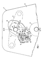
- two opposing rollers delimit a dough passage gap 4.
- the two pressure rollers 2, 3 are hidden in the view by the machine chassis 5 and are therefore indicated by dashed lines.
- the upper pressure roller 2 can be adjusted in height by means of a lifting device 6 (indicated by dash-dotted lines) along an elongated hole 7 for narrowing or widening the passage gap 4, and for this purpose the roller drive axis 8 is accommodated in a longitudinally displaceable manner in the elongated hole 7.
- the passage gap 4 is scanned by a light barrier 9 attached to the chassis 5.
- a wiper 10 (see also FIGS. 3, 4) that moves over the light barrier lens surface and is attached to the wiper control part 11 of an actuating member 12 serves to clean it.
- the wiper control part 11 is articulated on the machine chassis 5 so that it can pivot about the wiper control axis 14 (perpendicular to the plane of the drawing) against the force of a wiper return spring 15.
- the wiper return spring 15 is designed as a torsion spring and is supported with its one end 16 against the wiper control part 11 and with its other end 17 against a stop element 18 laterally attached to the chassis 5. As a result, the wiper control part 11 is pressed with a shoulder surface 19 facing the stop element 18 (perpendicular to the plane of the drawing) into a starting position in contact with the stop element 18.
- a freewheel coupling part 20 is pivotably articulated about a freewheel axis 21 (running perpendicular to the plane of the drawing) against the force of a coupling return spring 22.
- a coupling return spring 22 is supported against a pin 24 projecting (perpendicular to the plane of the drawing) from the freewheel coupling part 20, and its other end 25 is supported against an edge on the wiper control part 11.
- the coupling return spring 22 exerts a torque on the freewheel coupling part 20 - analogously to the wiper return spring 15 on the wiper actuating part 11 - on the basis of which the freewheel coupling part 20 is returned to an initial position in which its stop projection 26 rests on the contact surface 27 (perpendicular to the drawing plane) a support shoulder 28 of the wiper control part 11 rests.
- the wiper control and freewheel coupling parts 11, 20 together form an actuator 12 for the wiper 10, which cooperates with an actuating pin 29 with a release pin 30 in a corresponding position (cf. FIG. 4) via an actuating arm 29 projecting from the freewheel coupling part 20 in the direction of the passage gap 4.
- the release pin 30 is part of a release element 31 designed as a plastic sealing disk and projects from its side approximately parallel to the roller axis 8 transversely to the actuating arm 29.
- the trigger element 31 is articulated on the chassis 5 on the one hand about a pivot axis 32 (running perpendicular to the plane of the drawing) and on the other hand rotatably supported by the roller axis 8.
- the rotary bearing is implemented as a sliding bearing by using a sliding material for the sealing washer.
- the triggering element 31 is pivoted about its pivot axis 32 (see pivoting direction 34 in FIG. 1), so that the trigger pin 30 with the freewheel coupling part firmly connected actuating arm 29 a tilting movement 35 clockwise around the freewheel axis 21 against the force of the coupling return spring 22 issued.
- the stop projection 26 of the freewheel coupling part 20 is released from the contact surface 27 of the wiper control part 11 (not shown), which is not moved in the process.
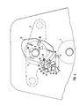
- the upper pressure roller 2 - continuing the movement explained with reference to FIG. 1 - is adjusted into a position for a minimum width of the passage gap 4, the release bolt 30 of the release member 31 moving past the actuating arm 29, and the actuating arm 29 from the Coupling return spring 22 have been returned to the starting or stop position on the contact surface 27. 4, the lifting device 6 has reversed the linear adjustment movement 36 for the upper pressure roller 2 along the elongated hole 7 and therefore the pivoting direction 34 for the release pin 30. After the release bolt 30 has pivoted the actuating arm 29 in a counterclockwise direction against its underside 37, it slides past the actuating arm 29 in the course of its circular path.
- a described wiper device is preferably arranged symmetrically on both sides of the dough passage gap 4 or a corresponding central axis.
Landscapes
- Life Sciences & Earth Sciences (AREA)
- Engineering & Computer Science (AREA)
- Food Science & Technology (AREA)
- Transmission Devices (AREA)
- Cleaning In General (AREA)
- Coating Apparatus (AREA)
- Manufacturing And Processing Devices For Dough (AREA)
Applications Claiming Priority (4)
| Application Number | Priority Date | Filing Date | Title |
|---|---|---|---|
| DE4011667 | 1990-04-11 | ||
| DE4011667 | 1990-04-11 | ||
| DE4013517 | 1990-04-27 | ||
| DE4013517A DE4013517A1 (de) | 1990-04-11 | 1990-04-27 | Wischvorrichtung zum reinigen von lichtschranken in teigwalzmaschinen |
Publications (2)
| Publication Number | Publication Date |
|---|---|
| EP0451489A1 EP0451489A1 (de) | 1991-10-16 |
| EP0451489B1 true EP0451489B1 (de) | 1993-11-03 |
Family
ID=25892092
Family Applications (1)
| Application Number | Title | Priority Date | Filing Date |
|---|---|---|---|
| EP91103072A Expired - Lifetime EP0451489B1 (de) | 1990-04-11 | 1991-03-01 | Wischvorrichtung zum Reinigen von Lichtschranken in Teigwalzmaschinen |
Country Status (5)
| Country | Link |
|---|---|
| EP (1) | EP0451489B1 (cg-RX-API-DMAC7.html) |
| AT (1) | ATE96610T1 (cg-RX-API-DMAC7.html) |
| DE (2) | DE4013517A1 (cg-RX-API-DMAC7.html) |
| DK (1) | DK0451489T3 (cg-RX-API-DMAC7.html) |
| ES (1) | ES2045968T3 (cg-RX-API-DMAC7.html) |
Family Cites Families (1)
| Publication number | Priority date | Publication date | Assignee | Title |
|---|---|---|---|---|
| DE8632366U1 (de) * | 1986-12-03 | 1987-01-29 | Seewer AG, Burgdorf, Bern | Reinigungsvorrichtung, insbesondere für Lichtschranken bei Teigauswalzmaschinen |
-
1990
- 1990-04-27 DE DE4013517A patent/DE4013517A1/de active Granted
-
1991
- 1991-03-01 ES ES91103072T patent/ES2045968T3/es not_active Expired - Lifetime
- 1991-03-01 EP EP91103072A patent/EP0451489B1/de not_active Expired - Lifetime
- 1991-03-01 AT AT91103072T patent/ATE96610T1/de not_active IP Right Cessation
- 1991-03-01 DK DK91103072.4T patent/DK0451489T3/da active
- 1991-03-01 DE DE91103072T patent/DE59100544D1/de not_active Expired - Lifetime
Also Published As
| Publication number | Publication date |
|---|---|
| DE59100544D1 (de) | 1993-12-09 |
| ATE96610T1 (de) | 1993-11-15 |
| ES2045968T3 (es) | 1994-01-16 |
| EP0451489A1 (de) | 1991-10-16 |
| DE4013517C2 (cg-RX-API-DMAC7.html) | 1992-01-23 |
| DK0451489T3 (da) | 1994-03-07 |
| DE4013517A1 (de) | 1991-10-17 |
Similar Documents
| Publication | Publication Date | Title |
|---|---|---|
| DE2146316C3 (de) | Staubsaugermundstück | |
| DE4222948A1 (de) | Schmetterlings-bodenwischer | |
| DE2319196C2 (de) | Lageranordnung für das Quetschwalzenpaar einer Selbstentwicklerkamera | |
| DE68914039T2 (de) | Wischlappen-Auswringeinheit. | |
| DE2611285C2 (de) | Schrittschalteinrichtung für Drehelemente bei Werkzeugmaschinen | |
| EP1012099A1 (de) | Einrichtung zur handhabung blattartiger fördergutstücke | |
| EP0163772B1 (de) | Staubsaugermundstück | |
| EP0451489B1 (de) | Wischvorrichtung zum Reinigen von Lichtschranken in Teigwalzmaschinen | |
| DE2234670C3 (de) | Vorrichtung zum Abbiegen der Enden von Offsetdruckplatten | |
| DE2612160A1 (de) | Staubsaugermundstueck mit zwei alternativ verwendbaren werkzeugen | |
| EP0515375B1 (de) | Feststellvorrichtung für türflügel mit einem türschliesser | |
| DE2201157B2 (de) | Rückstelleinrichtung an Schaltern, insbesondere an Fahrtrichtungsschaltern für Kraftfahrzeuge* | |
| WO1999001062A1 (de) | Reinigungsgerät | |
| EP0004337B1 (de) | Einrichtung zum Entwickeln von Druckplatten mit paarweise horizontal angeordneten oberen und unteren Walzen | |
| EP0374124B1 (de) | Verschlussmechanik für Ordner für gelochte Blätter | |
| DE1554691A1 (de) | Vorrichtung zur Entnahme von Tuechern,Lappen od.dgl. aus einem Behaelter | |
| DE3042829C2 (de) | Betätigungsgetriebe für Treibstangenbeschläge o.dgl. | |
| DE2907464C2 (de) | Sicherheitseinrichtung zum periodischen Abtasten auf Anwesenheit eines Werkstückes von mindestens einem Stempel und zum Kühlen der Stirnfläche mindestens eines Stempels an einer automatischen Quertransportpresse zur Umformung von Metallteilen | |
| DE1760544C3 (de) | TürverschluB für eine mit einer Rundumdichtung versehene Beschickungstür einer Wasch- oder Geschirrspülmaschine | |
| DE2405604A1 (de) | Scharnier, insbesondere moebelscharnier | |
| DE2126347A1 (de) | Vorrichtung zum Reinigen der Rader von Fahrzeugen | |
| DE919784C (de) | Rechenmaschine mit einem mechanisch schaltbaren Schlitten | |
| DE1174601B (de) | Naehmaschine | |
| DE7322061U (de) | Etikettiermaschine für selbstklebende Abziehetiketten | |
| DE3335645C2 (cg-RX-API-DMAC7.html) |
Legal Events
| Date | Code | Title | Description |
|---|---|---|---|
| PUAI | Public reference made under article 153(3) epc to a published international application that has entered the european phase |
Free format text: ORIGINAL CODE: 0009012 |
|
| 17P | Request for examination filed |
Effective date: 19910816 |
|
| AK | Designated contracting states |
Kind code of ref document: A1 Designated state(s): AT BE CH DE DK ES FR GB GR IT LI LU NL SE |
|
| 17Q | First examination report despatched |
Effective date: 19930121 |
|
| GRAA | (expected) grant |
Free format text: ORIGINAL CODE: 0009210 |
|
| AK | Designated contracting states |
Kind code of ref document: B1 Designated state(s): AT BE CH DE DK ES FR GB GR IT LI LU NL SE |
|
| PG25 | Lapsed in a contracting state [announced via postgrant information from national office to epo] |
Ref country code: GR Free format text: LAPSE BECAUSE OF FAILURE TO SUBMIT A TRANSLATION OF THE DESCRIPTION OR TO PAY THE FEE WITHIN THE PRESCRIBED TIME-LIMIT Effective date: 19931103 |
|
| REF | Corresponds to: |
Ref document number: 96610 Country of ref document: AT Date of ref document: 19931115 Kind code of ref document: T |
|
| REF | Corresponds to: |
Ref document number: 59100544 Country of ref document: DE Date of ref document: 19931209 |
|
| ITF | It: translation for a ep patent filed | ||
| GBT | Gb: translation of ep patent filed (gb section 77(6)(a)/1977) |
Effective date: 19931208 |
|
| REG | Reference to a national code |
Ref country code: ES Ref legal event code: FG2A Ref document number: 2045968 Country of ref document: ES Kind code of ref document: T3 |
|
| ET | Fr: translation filed | ||
| REG | Reference to a national code |
Ref country code: DK Ref legal event code: T3 |
|
| PG25 | Lapsed in a contracting state [announced via postgrant information from national office to epo] |
Ref country code: LU Free format text: LAPSE BECAUSE OF NON-PAYMENT OF DUE FEES Effective date: 19940331 |
|
| PLBE | No opposition filed within time limit |
Free format text: ORIGINAL CODE: 0009261 |
|
| STAA | Information on the status of an ep patent application or granted ep patent |
Free format text: STATUS: NO OPPOSITION FILED WITHIN TIME LIMIT |
|
| 26N | No opposition filed | ||
| EAL | Se: european patent in force in sweden |
Ref document number: 91103072.4 |
|
| PGFP | Annual fee paid to national office [announced via postgrant information from national office to epo] |
Ref country code: BE Payment date: 19950202 Year of fee payment: 5 |
|
| PGFP | Annual fee paid to national office [announced via postgrant information from national office to epo] |
Ref country code: ES Payment date: 19950221 Year of fee payment: 5 |
|
| PGFP | Annual fee paid to national office [announced via postgrant information from national office to epo] |
Ref country code: AT Payment date: 19950227 Year of fee payment: 5 |
|
| PGFP | Annual fee paid to national office [announced via postgrant information from national office to epo] |
Ref country code: SE Payment date: 19950316 Year of fee payment: 5 |
|
| PGFP | Annual fee paid to national office [announced via postgrant information from national office to epo] |
Ref country code: DK Payment date: 19950331 Year of fee payment: 5 |
|
| PG25 | Lapsed in a contracting state [announced via postgrant information from national office to epo] |
Ref country code: DK Effective date: 19960301 Ref country code: AT Effective date: 19960301 |
|
| REG | Reference to a national code |
Ref country code: DK Ref legal event code: EBP |
|
| PG25 | Lapsed in a contracting state [announced via postgrant information from national office to epo] |
Ref country code: SE Effective date: 19960302 Ref country code: ES Free format text: LAPSE BECAUSE OF NON-PAYMENT OF DUE FEES Effective date: 19960302 |
|
| PG25 | Lapsed in a contracting state [announced via postgrant information from national office to epo] |
Ref country code: BE Effective date: 19960331 |
|
| BERE | Be: lapsed |
Owner name: A. FRITSCH G.M.B.H. & CO. K.G. Effective date: 19960331 |
|
| EUG | Se: european patent has lapsed |
Ref document number: 91103072.4 |
|
| REG | Reference to a national code |
Ref country code: ES Ref legal event code: FD2A Effective date: 19990301 |
|
| REG | Reference to a national code |
Ref country code: GB Ref legal event code: IF02 |
|
| PGFP | Annual fee paid to national office [announced via postgrant information from national office to epo] |
Ref country code: GB Payment date: 20020228 Year of fee payment: 12 Ref country code: NL Payment date: 20020228 Year of fee payment: 12 |
|
| PG25 | Lapsed in a contracting state [announced via postgrant information from national office to epo] |
Ref country code: GB Free format text: LAPSE BECAUSE OF NON-PAYMENT OF DUE FEES Effective date: 20030301 |
|
| PG25 | Lapsed in a contracting state [announced via postgrant information from national office to epo] |
Ref country code: NL Free format text: LAPSE BECAUSE OF NON-PAYMENT OF DUE FEES Effective date: 20031001 |
|
| GBPC | Gb: european patent ceased through non-payment of renewal fee | ||
| NLV4 | Nl: lapsed or anulled due to non-payment of the annual fee |
Effective date: 20031001 |
|
| PG25 | Lapsed in a contracting state [announced via postgrant information from national office to epo] |
Ref country code: IT Free format text: LAPSE BECAUSE OF NON-PAYMENT OF DUE FEES;WARNING: LAPSES OF ITALIAN PATENTS WITH EFFECTIVE DATE BEFORE 2007 MAY HAVE OCCURRED AT ANY TIME BEFORE 2007. THE CORRECT EFFECTIVE DATE MAY BE DIFFERENT FROM THE ONE RECORDED. Effective date: 20050301 |
|
| REG | Reference to a national code |
Ref country code: CH Ref legal event code: PCAR Free format text: ISLER & PEDRAZZINI AG;POSTFACH 1772;8027 ZUERICH (CH) |
|
| PGFP | Annual fee paid to national office [announced via postgrant information from national office to epo] |
Ref country code: FR Payment date: 20080311 Year of fee payment: 18 |
|
| REG | Reference to a national code |
Ref country code: FR Ref legal event code: ST Effective date: 20091130 |
|
| PG25 | Lapsed in a contracting state [announced via postgrant information from national office to epo] |
Ref country code: FR Free format text: LAPSE BECAUSE OF NON-PAYMENT OF DUE FEES Effective date: 20091123 |
|
| PGFP | Annual fee paid to national office [announced via postgrant information from national office to epo] |
Ref country code: CH Payment date: 20100315 Year of fee payment: 20 |
|
| PGFP | Annual fee paid to national office [announced via postgrant information from national office to epo] |
Ref country code: DE Payment date: 20100521 Year of fee payment: 20 |
|
| REG | Reference to a national code |
Ref country code: DE Ref legal event code: R071 Ref document number: 59100544 Country of ref document: DE |
|
| REG | Reference to a national code |
Ref country code: CH Ref legal event code: PL |
|
| PG25 | Lapsed in a contracting state [announced via postgrant information from national office to epo] |
Ref country code: DE Free format text: LAPSE BECAUSE OF EXPIRATION OF PROTECTION Effective date: 20110301 |