EP0451102B1 - Verschlusskappe aus Kunststoff - Google Patents
Verschlusskappe aus Kunststoff Download PDFInfo
- Publication number
- EP0451102B1 EP0451102B1 EP91810216A EP91810216A EP0451102B1 EP 0451102 B1 EP0451102 B1 EP 0451102B1 EP 91810216 A EP91810216 A EP 91810216A EP 91810216 A EP91810216 A EP 91810216A EP 0451102 B1 EP0451102 B1 EP 0451102B1
- Authority
- EP
- European Patent Office
- Prior art keywords
- location
- closure cap
- tearing
- beginning
- section
- Prior art date
- Legal status (The legal status is an assumption and is not a legal conclusion. Google has not performed a legal analysis and makes no representation as to the accuracy of the status listed.)
- Expired - Lifetime
Links
Images

Classifications
-
- B—PERFORMING OPERATIONS; TRANSPORTING
- B65—CONVEYING; PACKING; STORING; HANDLING THIN OR FILAMENTARY MATERIAL
- B65D—CONTAINERS FOR STORAGE OR TRANSPORT OF ARTICLES OR MATERIALS, e.g. BAGS, BARRELS, BOTTLES, BOXES, CANS, CARTONS, CRATES, DRUMS, JARS, TANKS, HOPPERS, FORWARDING CONTAINERS; ACCESSORIES, CLOSURES, OR FITTINGS THEREFOR; PACKAGING ELEMENTS; PACKAGES
- B65D41/00—Caps, e.g. crown caps or crown seals, i.e. members having parts arranged for engagement with the external periphery of a neck or wall defining a pouring opening or discharge aperture; Protective cap-like covers for closure members, e.g. decorative covers of metal foil or paper
- B65D41/32—Caps or cap-like covers with lines of weakness, tearing-strips, tags, or like opening or removal devices, e.g. to facilitate formation of pouring openings
- B65D41/34—Threaded or like caps or cap-like covers provided with tamper elements formed in, or attached to, the closure skirt
- B65D41/3442—Threaded or like caps or cap-like covers provided with tamper elements formed in, or attached to, the closure skirt with rigid bead or projections formed on the tamper element and coacting with bead or projections on the container
- B65D41/3447—Threaded or like caps or cap-like covers provided with tamper elements formed in, or attached to, the closure skirt with rigid bead or projections formed on the tamper element and coacting with bead or projections on the container the tamper element being integrally connected to the closure by means of bridges
Definitions
- the invention relates to a sealing cap made of plastic with a guarantee band according to the preamble of patent claim 1.
- Such caps with a guarantee band, which is connected to the cap with a plurality of connecting webs, are becoming increasingly popular with consumers.
- the guarantee band is designed in such a way that it is attached to the neck of the container by shrinking or by positive locking or by molding on corresponding beads, cams or in undercuts.
- a vertical (or more vertical) predetermined breaking line is also provided in addition to the connecting webs on the guarantee band itself.
- Sealing caps are known both as screw caps with an internal thread and as snap caps or with other forms of fastening to the container neck (e.g. bayonet-type locking).
- EP patent 154 603. There is shown a screw cap with a so-called mechanical guarantee band, which snaps over a complementary bulge on the container neck when it is first put on with several retaining cams and a bead on the guarantee band.
- the guarantee tape is permanently connected to the screw cap on one side with a web.
- This closure cap according to EP patent 154 603 and also the other types and types of the types of closure caps described at the outset can be further improved with regard to their guarantee properties.
- a problem with the known caps is that the connecting webs should be sufficiently strong and resilient, on the one hand, to prevent them from being handled, from being ejected from injection molds, from being stored in large containers or from being screwed onto the bottle and from being snapped over a container bead or during thermoforming to tear or get damaged.
- each connecting bridge should be extremely sensitive to any type of tensile load, in order to tear as early as possible when it is first unscrewed and to reliably fulfill its guarantee function. These conflicting requirements are particularly difficult to meet with mechanical guarantee tapes. There, namely, when the cap is screwed on, a relatively large load is exerted on the connecting webs if the guarantee band snaps over the complementary bead on the bottle or the container.
- the invention has for its object to avoid the disadvantages of the known, in particular to create a closure cap of the types described above, which on the one hand fulfills its guarantee function well, i.e. that is, it tears quickly and reliably when opened, but which, on the other hand, has sufficient stability for the entire manufacturing and handling process.
- such a closure has a plurality, that is to say at least two, but preferably at least four, connecting webs. At least two webs adjacent to a certain point are facing at this point Side weakened.
- this weakening means, for example, a greater tendency to tear, so that whenever a tensile load is exerted on the guarantee tape from this point, a crack virtually propagates laterally away from the stated point through the adjacent and subsequent connecting webs.
- Means should preferably be provided to provoke the start of the crack at a certain point on the circumference of the guarantee band.
- This can e.g. can be achieved in that at one point the holding cams are designed, in particular raised or deepened, that tensile forces are introduced into the guarantee band there when they are opened.
- This effect can be achieved particularly reliably if the zone of the fixed connection between the guarantee band and the screw closure is provided over a circumferential angle of 130 ° to 240 °. Particularly good results are obtained at around 180 ° to 210 °.
- the guarantee band into two or three sections, each of which is permanently connected to the screw cap by means of a fixed web, and then to provide points with a predetermined start of the crack in the segments delimited by the fixed webs.
- the invention can be implemented in a technically particularly simple manner if the connecting webs are tapered in cross-section to the location of the intended crack start.
- the cross-sections of the webs can thus be, for example, “wedge-shaped”.
- "Wedge-shaped” also captures such configurations in which one or more of the side surfaces of the wedge are concave or convex curved.
- a wedge angle of approximately 15 ° to 30 ° and preferably approximately 20 ° is particularly suitable for the invention. It has been shown that wedge tips with this angle tear relatively quickly under tensile load, while the thickened side facing away from the rice pad is sufficiently stable to ensure manipulation and handling of the screw cap before putting on and when putting on without breaking the connecting webs.
- the connecting web can also be weakened in another way and, for example, cut horizontally or provided with one or more notches.
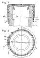
- a closure cap 1 produced by the injection molding process is provided with a guarantee tape 2.
- the closure cap 1 is permanently connected to the guarantee band 2 by means of a web section 3 over a circumferential angle alpha of approximately 210 °. In the area of the remaining circumferential angle, however, the guarantee band 2 is connected by five connecting webs 4.
- the guarantee band 2 has on its inside a circumferential bead 5 with which the guarantee band 2 underneath can engage a complementary bead 6 on a beverage bottle.
- the bead 5 runs downward at an acute angle, so that the guarantee tape 2 can be slowly stretched when screwed onto the bottle and snapped over the complementary bead 6 on the bottle neck.
- the guarantee band 2 is also provided with the bead 5 in the region of the web section 3, an increased tensile stress is exerted on the side opposite the web section 3 approximately in the direction of arrow A when it is first opened.
- the bead 5 in the web area 3 is pressed away from the container neck in the direction of arrow B according to FIG. 1, as a result of which it engages more firmly on the opposite side and thereby reliably tears at the beginning of the opening.
- the tearing of the connecting webs 4 is therefore particularly provoked in the area between the two connecting webs 4a and 4b.
- the webs 4 are approximately wedge-shaped, with all webs with their wedge tip, i.e. that is, their thinner and weaker edges are directed to point P, where the tearing process is to begin.
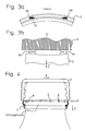
- the guarantee band 2 forms a downward "loop" after the start of the tearing process, because the closure is tilted somewhat on the bottle neck 7. As soon as this position is reached, the tearing process propagates quickly from the point P over the other webs 4 when the closure cap 1 is opened further. This loop formation in the direction of arrow C can also be seen particularly well from FIG. 4.
- the connecting webs 4 tapering in the direction of the point P are provided on each side facing away from the point P with a thickened section which ensures that the guarantee tape 2 is not damaged during handling or during manufacture, in particular when ejecting from an injection molding tool that in particular the connecting webs 4 do not break or tear.
- the cross section of the guarantee band can also be modified, e.g. the taper to the "wedge tip” may be pointed or blunt, depending on the plastic material used and the container or closure configuration.
- the thickness and the total length of the webs 4 and the width of the reinforced end facing away from point B can also be adapted to the special circumstances, in particular the tear resistance of the plastic used and the load-bearing capacity of the connection between the guarantee band and the container.
- the length of the web section 3 can obviously also be optimized by simple tests. For example, very good results can be achieved with circumferential angles alpha of 170 ° to 210 °.
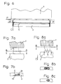
- FIG. 4 shows an exemplary embodiment in which a heat-formable guarantee tape 2 was tapered and molded on in a known manner below a bead 6 on the container according to FIG. 7 by pressing or shrinking.
- the cross-sectional shape of the connecting webs 4 corresponds to the exemplary embodiment according to FIGS. 1 to 3.
- Figure 5 shows a modified embodiment in which two relatively narrow web sections 3 are provided.
- the "loop formation" described above occurs when the closure is opened at the two points C1 and C2 between the two web sections Insert 3a and 3b.
- the connecting webs 4 are directed towards the two points P1 and P2 analogously to the exemplary embodiment according to FIGS. 1 to 4, with their tapering sides, so that the cracking process can be reliably initiated there.
- FIG. 6 shows an exemplary embodiment of a closure cap 1 in which the distance a2 from the apex of the bead 5 to the upper edge of the guarantee band in the region of the point P is smaller than the distance a1 on the opposite side. Accordingly, in the area of the smaller distance a2, when the inner bead 5 is screwed on, the complementary bead 6 (FIG. 1) will first come into engagement on the container neck 7. The train on the guarantee tape 2 thus begins in the area of the point P, so that loops are formed in the direction of the arrow C.
- the start of the crack is determined solely by the stretching and loop formation of the guarantee band in the area of greatest weakening, i.e.
- means are provided in the exemplary embodiment according to FIG. 6 as well as in the exemplary embodiments according to FIGS. 1 to 4 in order to particularly provoke the start of the crack at a specific point. This is also achieved by cams or deeper bead formation.
- Figures 7a and 7b show the shape of the connecting webs 4 schematically and on an enlarged scale.
- the connecting webs 4 are accordingly formed with a section 4c which is approximately rectangular in cross section, which merges into a tapering section 4d in which the plastic material is particularly stretchable due to its elasticity and thus tends to yield. This stretch leads to the above described loop formation, from which the cracking process is derived directly.
- FIG. 8 shows a modified exemplary embodiment, in which the webs 4 are additionally weakened in their lower region by a notch 8. Every pull in the direction of arrow C causes the guarantee strip 2 to tip down, which causes the crack to start.
- the notch could also have a different geometric shape and e.g. be provided in the middle section of the connecting web 4, the weakening could be formed as a perforation on one side of the connecting web 4 or subsequently made as an incision.
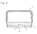
- FIG. 9 shows an exemplary embodiment of a closure cap 1 with a guarantee band 2 with an inner bead 5.
- An elevation 8 is provided on the inner bead 5, which at this point causes firmer and earlier engagement with a complementary bead 6 (FIG. 1) of a container neck 7.
- FIG. 9 shows an exemplary embodiment of a closure cap 1 with a guarantee band 2 with an inner bead 5.
- An elevation 8 is provided on the inner bead 5, which at this point causes firmer and earlier engagement with a complementary bead 6 (FIG. 1) of a container neck 7.
Landscapes
- Engineering & Computer Science (AREA)
- Mechanical Engineering (AREA)
- Closures For Containers (AREA)
- Tubes (AREA)
- Professional, Industrial, Or Sporting Protective Garments (AREA)
- Package Frames And Binding Bands (AREA)
- Diaphragms And Bellows (AREA)
- Cartons (AREA)
Applications Claiming Priority (2)
| Application Number | Priority Date | Filing Date | Title |
|---|---|---|---|
| CH1133/90 | 1990-04-04 | ||
| CH113390 | 1990-04-04 |
Publications (2)
| Publication Number | Publication Date |
|---|---|
| EP0451102A1 EP0451102A1 (de) | 1991-10-09 |
| EP0451102B1 true EP0451102B1 (de) | 1993-10-06 |
Family
ID=4203269
Family Applications (1)
| Application Number | Title | Priority Date | Filing Date |
|---|---|---|---|
| EP91810216A Expired - Lifetime EP0451102B1 (de) | 1990-04-04 | 1991-03-26 | Verschlusskappe aus Kunststoff |
Country Status (7)
| Country | Link |
|---|---|
| US (1) | US5074425A (es) |
| EP (1) | EP0451102B1 (es) |
| AT (1) | ATE95488T1 (es) |
| CA (1) | CA2039619A1 (es) |
| DE (1) | DE59100444D1 (es) |
| DK (1) | DK0451102T3 (es) |
| ES (1) | ES2044711T3 (es) |
Cited By (1)
| Publication number | Priority date | Publication date | Assignee | Title |
|---|---|---|---|---|
| EP0965533A1 (de) | 1998-06-18 | 1999-12-22 | Mouldtec Kunststoff GmbH | Verschlusskappe, insbesondere Schraubkappe aus Kunststoff mit einem Garantieband |
Families Citing this family (12)
| Publication number | Priority date | Publication date | Assignee | Title |
|---|---|---|---|---|
| GB9205374D0 (en) * | 1992-03-12 | 1992-04-22 | Metal Closures Group Ltd | Container closures |
| DE4211992A1 (de) * | 1992-04-09 | 1993-10-14 | Mouldtec Pvg Ag Meilen | Flaschenkappe mit Sicherungsring |
| US5405032A (en) * | 1992-11-06 | 1995-04-11 | Crown Cork & Seal Company, Inc. | Tamper indicating closure and method and device for the manufacture of a tamper-indicating closure |
| IT1274907B (it) * | 1994-09-20 | 1997-07-25 | Pelliconi Abruzzo Srl | Capsula in plastica con fascetta di garanzia. |
| US5501349A (en) * | 1994-10-27 | 1996-03-26 | H-C Industries, Inc. | Tamper-indicating plastic closure with selectively strengthened pilfer band |
| US6491175B1 (en) * | 2000-06-28 | 2002-12-10 | Saad Taha | Single piece closure for a pressurized container |
| WO2004014742A2 (en) * | 2002-08-07 | 2004-02-19 | Silgan Closures, Llc | Reduced application energy closure |
| WO2005012129A1 (en) * | 2003-08-01 | 2005-02-10 | Liqui-Box Canada Inc. | Tamper evident fitment assembly |
| WO2019207149A1 (en) * | 2018-04-26 | 2019-10-31 | Obrist Closures Switzerland Gmbh | Closure |
| EP3938288B1 (de) * | 2019-03-11 | 2024-05-01 | ALPLA Werke Alwin Lehner GmbH & Co. KG | Behälterverschluss und behälter |
| FR3104144B1 (fr) * | 2019-12-04 | 2021-12-03 | Soc Lorraine De Capsules Metalliques Manufacture De Bouchage | Dispositif de bouchage à vis destiné à rester attaché à un récipient après ouverture du récipient. |
| US20220041339A1 (en) * | 2020-08-07 | 2022-02-10 | Niagara Bottling, Llc | Single anchor closure |
Family Cites Families (6)
| Publication number | Priority date | Publication date | Assignee | Title |
|---|---|---|---|---|
| US4432461A (en) * | 1982-04-09 | 1984-02-21 | Owens-Illinois, Inc. | Tamper indicating package |
| DE3377637D1 (en) * | 1982-05-06 | 1988-09-15 | Anchor Hocking Corp | Tamperproof beverage closure |
| GB2191766A (en) * | 1986-06-17 | 1987-12-23 | Grace W R & Co | Screw container with tamper-evident feature |
| CH671205A5 (es) * | 1987-02-26 | 1989-08-15 | Crown Cork Ag | |
| US4923073A (en) * | 1989-01-30 | 1990-05-08 | H-C Industries, Inc. | Tamper-indicating plastic closure |
| US4967920A (en) * | 1989-06-26 | 1990-11-06 | Continental White Cap, Inc. | Partial tamper band |
-
1991
- 1991-03-26 AT AT91810216T patent/ATE95488T1/de not_active IP Right Cessation
- 1991-03-26 ES ES91810216T patent/ES2044711T3/es not_active Expired - Lifetime
- 1991-03-26 DE DE91810216T patent/DE59100444D1/de not_active Expired - Fee Related
- 1991-03-26 DK DK91810216.1T patent/DK0451102T3/da active
- 1991-03-26 EP EP91810216A patent/EP0451102B1/de not_active Expired - Lifetime
- 1991-04-03 CA CA002039619A patent/CA2039619A1/en not_active Abandoned
- 1991-04-04 US US07/680,299 patent/US5074425A/en not_active Expired - Fee Related
Cited By (1)
| Publication number | Priority date | Publication date | Assignee | Title |
|---|---|---|---|---|
| EP0965533A1 (de) | 1998-06-18 | 1999-12-22 | Mouldtec Kunststoff GmbH | Verschlusskappe, insbesondere Schraubkappe aus Kunststoff mit einem Garantieband |
Also Published As
| Publication number | Publication date |
|---|---|
| ATE95488T1 (de) | 1993-10-15 |
| DE59100444D1 (de) | 1993-11-11 |
| ES2044711T3 (es) | 1994-01-01 |
| US5074425A (en) | 1991-12-24 |
| EP0451102A1 (de) | 1991-10-09 |
| CA2039619A1 (en) | 1991-10-05 |
| DK0451102T3 (da) | 1993-11-22 |
Similar Documents
| Publication | Publication Date | Title |
|---|---|---|
| DE69323423T2 (de) | Gegen manipulation gesicherter schraubverschluss | |
| EP0810952B1 (de) | Verschlusskappe mit fangband | |
| EP0593396B1 (de) | Garantieverschluss aus Kunststoff | |
| DE2910178C2 (de) | Originalitäts-Schraubverschluß für Flaschen u.dgl | |
| EP0714369B1 (de) | Schraubkappe mit garantieband | |
| EP0451102B1 (de) | Verschlusskappe aus Kunststoff | |
| WO1996000171A1 (de) | Verschlusskappe mit garantiering | |
| DE10207204A1 (de) | Kombination aus einer Flasche mit rastgehaltertem Adapter und/oder einer Verschlusskappe | |
| DE69001798T2 (de) | Schraubverschlusskappe mit originalitaetsband. | |
| EP0951428B1 (de) | Flaschen-schraubverschluss aus kunststoff mit garantieband | |
| EP0254673A1 (de) | Sicherheitsband an einem Gebindeverschluss | |
| EP0371920B1 (de) | Schraubkappe mit Garantieband | |
| EP0281514A1 (de) | Verschlusskappe mit Garantieband | |
| EP2906475A1 (de) | Verschlusskappe, behälterhals, garantieverschluss sowie verfahren zur herstellung eines garantieverschlusses | |
| EP0243531A2 (de) | Sicherungsring für Flaschen-, Weithals- o.ä. Behälterverschlüsse | |
| DE2753080C2 (de) | Verschlußkappe mit Originalitätssicherung | |
| DE3912137A1 (de) | Aus kunststoff bestehende verschlusskappe fuer einen behaelter | |
| EP0099332A2 (de) | Verschlusskappe für einen Behälter | |
| EP3938290B1 (de) | Behälterverschluss | |
| DE3727887C2 (es) | ||
| DE4317269C1 (de) | Originalitäts-Sicherungsvorrichtung für Behälterverschlüsse | |
| EP0886606B1 (de) | Behältermündung und verschlusskappe | |
| EP0886605B1 (de) | Garantieverschlusskappe aus kunststoff | |
| EP1151932A1 (de) | Kunststoff-Verschlusskappe, insbesondere Schraubkappe, mit Garantieband | |
| DE10024072C1 (de) | Kunststoff-Verschlusskappe, insbesondere Schraubkappe, mit Garantieband |
Legal Events
| Date | Code | Title | Description |
|---|---|---|---|
| PUAI | Public reference made under article 153(3) epc to a published international application that has entered the european phase |
Free format text: ORIGINAL CODE: 0009012 |
|
| AK | Designated contracting states |
Kind code of ref document: A1 Designated state(s): AT BE CH DE DK ES FR GB IT LI NL SE |
|
| 17P | Request for examination filed |
Effective date: 19920210 |
|
| 17Q | First examination report despatched |
Effective date: 19921007 |
|
| GRAA | (expected) grant |
Free format text: ORIGINAL CODE: 0009210 |
|
| ITF | It: translation for a ep patent filed | ||
| AK | Designated contracting states |
Kind code of ref document: B1 Designated state(s): AT BE CH DE DK ES FR GB IT LI NL SE |
|
| REF | Corresponds to: |
Ref document number: 95488 Country of ref document: AT Date of ref document: 19931015 Kind code of ref document: T |
|
| REF | Corresponds to: |
Ref document number: 59100444 Country of ref document: DE Date of ref document: 19931111 |
|
| REG | Reference to a national code |
Ref country code: DK Ref legal event code: T3 |
|
| REG | Reference to a national code |
Ref country code: ES Ref legal event code: FG2A Ref document number: 2044711 Country of ref document: ES Kind code of ref document: T3 |
|
| GBT | Gb: translation of ep patent filed (gb section 77(6)(a)/1977) |
Effective date: 19931202 |
|
| ET | Fr: translation filed | ||
| ITTA | It: last paid annual fee | ||
| PLBE | No opposition filed within time limit |
Free format text: ORIGINAL CODE: 0009261 |
|
| 26N | No opposition filed | ||
| EAL | Se: european patent in force in sweden |
Ref document number: 91810216.1 |
|
| PGFP | Annual fee paid to national office [announced via postgrant information from national office to epo] |
Ref country code: DK Payment date: 19980210 Year of fee payment: 8 |
|
| PGFP | Annual fee paid to national office [announced via postgrant information from national office to epo] |
Ref country code: SE Payment date: 19980217 Year of fee payment: 8 |
|
| PGFP | Annual fee paid to national office [announced via postgrant information from national office to epo] |
Ref country code: NL Payment date: 19980228 Year of fee payment: 8 |
|
| PG25 | Lapsed in a contracting state [announced via postgrant information from national office to epo] |
Ref country code: SE Free format text: LAPSE BECAUSE OF NON-PAYMENT OF DUE FEES Effective date: 19990327 |
|
| PG25 | Lapsed in a contracting state [announced via postgrant information from national office to epo] |
Ref country code: DK Free format text: LAPSE BECAUSE OF NON-PAYMENT OF DUE FEES Effective date: 19990331 |
|
| PG25 | Lapsed in a contracting state [announced via postgrant information from national office to epo] |
Ref country code: NL Free format text: LAPSE BECAUSE OF NON-PAYMENT OF DUE FEES Effective date: 19991001 |
|
| EUG | Se: european patent has lapsed |
Ref document number: 91810216.1 |
|
| NLV4 | Nl: lapsed or anulled due to non-payment of the annual fee |
Effective date: 19991001 |
|
| EUG | Se: european patent has lapsed |
Ref document number: 91810216.1 |
|
| REG | Reference to a national code |
Ref country code: DK Ref legal event code: EBP |
|
| PGFP | Annual fee paid to national office [announced via postgrant information from national office to epo] |
Ref country code: FR Payment date: 20010208 Year of fee payment: 11 |
|
| PGFP | Annual fee paid to national office [announced via postgrant information from national office to epo] |
Ref country code: GB Payment date: 20010219 Year of fee payment: 11 |
|
| PGFP | Annual fee paid to national office [announced via postgrant information from national office to epo] |
Ref country code: ES Payment date: 20010308 Year of fee payment: 11 |
|
| REG | Reference to a national code |
Ref country code: GB Ref legal event code: IF02 |
|
| PG25 | Lapsed in a contracting state [announced via postgrant information from national office to epo] |
Ref country code: GB Free format text: LAPSE BECAUSE OF NON-PAYMENT OF DUE FEES Effective date: 20020326 |
|
| PG25 | Lapsed in a contracting state [announced via postgrant information from national office to epo] |
Ref country code: ES Free format text: LAPSE BECAUSE OF NON-PAYMENT OF DUE FEES Effective date: 20020327 |
|
| GBPC | Gb: european patent ceased through non-payment of renewal fee |
Effective date: 20020326 |
|
| PG25 | Lapsed in a contracting state [announced via postgrant information from national office to epo] |
Ref country code: FR Free format text: LAPSE BECAUSE OF NON-PAYMENT OF DUE FEES Effective date: 20021129 |
|
| REG | Reference to a national code |
Ref country code: FR Ref legal event code: ST |
|
| REG | Reference to a national code |
Ref country code: ES Ref legal event code: FD2A Effective date: 20030410 |
|
| PGFP | Annual fee paid to national office [announced via postgrant information from national office to epo] |
Ref country code: AT Payment date: 20050208 Year of fee payment: 15 |
|
| PGFP | Annual fee paid to national office [announced via postgrant information from national office to epo] |
Ref country code: CH Payment date: 20050211 Year of fee payment: 15 |
|
| PGFP | Annual fee paid to national office [announced via postgrant information from national office to epo] |
Ref country code: DE Payment date: 20050216 Year of fee payment: 15 |
|
| PGFP | Annual fee paid to national office [announced via postgrant information from national office to epo] |
Ref country code: BE Payment date: 20050311 Year of fee payment: 15 |
|
| PG25 | Lapsed in a contracting state [announced via postgrant information from national office to epo] |
Ref country code: IT Free format text: LAPSE BECAUSE OF NON-PAYMENT OF DUE FEES;WARNING: LAPSES OF ITALIAN PATENTS WITH EFFECTIVE DATE BEFORE 2007 MAY HAVE OCCURRED AT ANY TIME BEFORE 2007. THE CORRECT EFFECTIVE DATE MAY BE DIFFERENT FROM THE ONE RECORDED. Effective date: 20050326 |
|
| PG25 | Lapsed in a contracting state [announced via postgrant information from national office to epo] |
Ref country code: AT Free format text: LAPSE BECAUSE OF NON-PAYMENT OF DUE FEES Effective date: 20060326 |
|
| PG25 | Lapsed in a contracting state [announced via postgrant information from national office to epo] |
Ref country code: LI Free format text: LAPSE BECAUSE OF NON-PAYMENT OF DUE FEES Effective date: 20060331 Ref country code: CH Free format text: LAPSE BECAUSE OF NON-PAYMENT OF DUE FEES Effective date: 20060331 Ref country code: BE Free format text: LAPSE BECAUSE OF NON-PAYMENT OF DUE FEES Effective date: 20060331 |
|
| PG25 | Lapsed in a contracting state [announced via postgrant information from national office to epo] |
Ref country code: DE Free format text: LAPSE BECAUSE OF NON-PAYMENT OF DUE FEES Effective date: 20061003 |
|
| REG | Reference to a national code |
Ref country code: CH Ref legal event code: PL |
|
| BERE | Be: lapsed |
Owner name: *CROWN CORK A.G. Effective date: 20060331 |