EP0451102B1 - Plastic closure - Google Patents
Plastic closure Download PDFInfo
- Publication number
- EP0451102B1 EP0451102B1 EP91810216A EP91810216A EP0451102B1 EP 0451102 B1 EP0451102 B1 EP 0451102B1 EP 91810216 A EP91810216 A EP 91810216A EP 91810216 A EP91810216 A EP 91810216A EP 0451102 B1 EP0451102 B1 EP 0451102B1
- Authority
- EP
- European Patent Office
- Prior art keywords
- location
- closure cap
- tearing
- beginning
- section
- Prior art date
- Legal status (The legal status is an assumption and is not a legal conclusion. Google has not performed a legal analysis and makes no representation as to the accuracy of the status listed.)
- Expired - Lifetime
Links
- 229920003023 plastic Polymers 0.000 title claims abstract description 7
- 239000004033 plastic Substances 0.000 title claims abstract description 7
- 239000000463 material Substances 0.000 claims description 3
- 230000007423 decrease Effects 0.000 claims 1
- 230000002093 peripheral effect Effects 0.000 claims 1
- 239000011324 bead Substances 0.000 description 23
- 230000000295 complement effect Effects 0.000 description 9
- 238000000034 method Methods 0.000 description 9
- 230000015572 biosynthetic process Effects 0.000 description 7
- 206010053648 Vascular occlusion Diseases 0.000 description 3
- 230000003313 weakening effect Effects 0.000 description 3
- 235000013361 beverage Nutrition 0.000 description 2
- 238000005336 cracking Methods 0.000 description 2
- 238000001746 injection moulding Methods 0.000 description 2
- 238000004519 manufacturing process Methods 0.000 description 2
- 238000007789 sealing Methods 0.000 description 2
- 240000007594 Oryza sativa Species 0.000 description 1
- 235000007164 Oryza sativa Nutrition 0.000 description 1
- 230000001154 acute effect Effects 0.000 description 1
- 230000000694 effects Effects 0.000 description 1
- 238000002347 injection Methods 0.000 description 1
- 239000007924 injection Substances 0.000 description 1
- 238000000465 moulding Methods 0.000 description 1
- 238000003825 pressing Methods 0.000 description 1
- 235000009566 rice Nutrition 0.000 description 1
- 238000003856 thermoforming Methods 0.000 description 1
Images

Classifications
-
- B—PERFORMING OPERATIONS; TRANSPORTING
- B65—CONVEYING; PACKING; STORING; HANDLING THIN OR FILAMENTARY MATERIAL
- B65D—CONTAINERS FOR STORAGE OR TRANSPORT OF ARTICLES OR MATERIALS, e.g. BAGS, BARRELS, BOTTLES, BOXES, CANS, CARTONS, CRATES, DRUMS, JARS, TANKS, HOPPERS, FORWARDING CONTAINERS; ACCESSORIES, CLOSURES, OR FITTINGS THEREFOR; PACKAGING ELEMENTS; PACKAGES
- B65D41/00—Caps, e.g. crown caps or crown seals, i.e. members having parts arranged for engagement with the external periphery of a neck or wall defining a pouring opening or discharge aperture; Protective cap-like covers for closure members, e.g. decorative covers of metal foil or paper
- B65D41/32—Caps or cap-like covers with lines of weakness, tearing-strips, tags, or like opening or removal devices, e.g. to facilitate formation of pouring openings
- B65D41/34—Threaded or like caps or cap-like covers provided with tamper elements formed in, or attached to, the closure skirt
- B65D41/3442—Threaded or like caps or cap-like covers provided with tamper elements formed in, or attached to, the closure skirt with rigid bead or projections formed on the tamper element and coacting with bead or projections on the container
- B65D41/3447—Threaded or like caps or cap-like covers provided with tamper elements formed in, or attached to, the closure skirt with rigid bead or projections formed on the tamper element and coacting with bead or projections on the container the tamper element being integrally connected to the closure by means of bridges
Definitions
- the invention relates to a sealing cap made of plastic with a guarantee band according to the preamble of patent claim 1.
- Such caps with a guarantee band, which is connected to the cap with a plurality of connecting webs, are becoming increasingly popular with consumers.
- the guarantee band is designed in such a way that it is attached to the neck of the container by shrinking or by positive locking or by molding on corresponding beads, cams or in undercuts.
- a vertical (or more vertical) predetermined breaking line is also provided in addition to the connecting webs on the guarantee band itself.
- Sealing caps are known both as screw caps with an internal thread and as snap caps or with other forms of fastening to the container neck (e.g. bayonet-type locking).
- EP patent 154 603. There is shown a screw cap with a so-called mechanical guarantee band, which snaps over a complementary bulge on the container neck when it is first put on with several retaining cams and a bead on the guarantee band.
- the guarantee tape is permanently connected to the screw cap on one side with a web.
- This closure cap according to EP patent 154 603 and also the other types and types of the types of closure caps described at the outset can be further improved with regard to their guarantee properties.
- a problem with the known caps is that the connecting webs should be sufficiently strong and resilient, on the one hand, to prevent them from being handled, from being ejected from injection molds, from being stored in large containers or from being screwed onto the bottle and from being snapped over a container bead or during thermoforming to tear or get damaged.
- each connecting bridge should be extremely sensitive to any type of tensile load, in order to tear as early as possible when it is first unscrewed and to reliably fulfill its guarantee function. These conflicting requirements are particularly difficult to meet with mechanical guarantee tapes. There, namely, when the cap is screwed on, a relatively large load is exerted on the connecting webs if the guarantee band snaps over the complementary bead on the bottle or the container.
- the invention has for its object to avoid the disadvantages of the known, in particular to create a closure cap of the types described above, which on the one hand fulfills its guarantee function well, i.e. that is, it tears quickly and reliably when opened, but which, on the other hand, has sufficient stability for the entire manufacturing and handling process.
- such a closure has a plurality, that is to say at least two, but preferably at least four, connecting webs. At least two webs adjacent to a certain point are facing at this point Side weakened.
- this weakening means, for example, a greater tendency to tear, so that whenever a tensile load is exerted on the guarantee tape from this point, a crack virtually propagates laterally away from the stated point through the adjacent and subsequent connecting webs.
- Means should preferably be provided to provoke the start of the crack at a certain point on the circumference of the guarantee band.
- This can e.g. can be achieved in that at one point the holding cams are designed, in particular raised or deepened, that tensile forces are introduced into the guarantee band there when they are opened.
- This effect can be achieved particularly reliably if the zone of the fixed connection between the guarantee band and the screw closure is provided over a circumferential angle of 130 ° to 240 °. Particularly good results are obtained at around 180 ° to 210 °.
- the guarantee band into two or three sections, each of which is permanently connected to the screw cap by means of a fixed web, and then to provide points with a predetermined start of the crack in the segments delimited by the fixed webs.
- the invention can be implemented in a technically particularly simple manner if the connecting webs are tapered in cross-section to the location of the intended crack start.
- the cross-sections of the webs can thus be, for example, “wedge-shaped”.
- "Wedge-shaped” also captures such configurations in which one or more of the side surfaces of the wedge are concave or convex curved.
- a wedge angle of approximately 15 ° to 30 ° and preferably approximately 20 ° is particularly suitable for the invention. It has been shown that wedge tips with this angle tear relatively quickly under tensile load, while the thickened side facing away from the rice pad is sufficiently stable to ensure manipulation and handling of the screw cap before putting on and when putting on without breaking the connecting webs.
- the connecting web can also be weakened in another way and, for example, cut horizontally or provided with one or more notches.
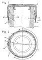
- a closure cap 1 produced by the injection molding process is provided with a guarantee tape 2.
- the closure cap 1 is permanently connected to the guarantee band 2 by means of a web section 3 over a circumferential angle alpha of approximately 210 °. In the area of the remaining circumferential angle, however, the guarantee band 2 is connected by five connecting webs 4.
- the guarantee band 2 has on its inside a circumferential bead 5 with which the guarantee band 2 underneath can engage a complementary bead 6 on a beverage bottle.
- the bead 5 runs downward at an acute angle, so that the guarantee tape 2 can be slowly stretched when screwed onto the bottle and snapped over the complementary bead 6 on the bottle neck.
- the guarantee band 2 is also provided with the bead 5 in the region of the web section 3, an increased tensile stress is exerted on the side opposite the web section 3 approximately in the direction of arrow A when it is first opened.
- the bead 5 in the web area 3 is pressed away from the container neck in the direction of arrow B according to FIG. 1, as a result of which it engages more firmly on the opposite side and thereby reliably tears at the beginning of the opening.
- the tearing of the connecting webs 4 is therefore particularly provoked in the area between the two connecting webs 4a and 4b.
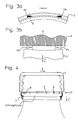
- the webs 4 are approximately wedge-shaped, with all webs with their wedge tip, i.e. that is, their thinner and weaker edges are directed to point P, where the tearing process is to begin.
- the guarantee band 2 forms a downward "loop" after the start of the tearing process, because the closure is tilted somewhat on the bottle neck 7. As soon as this position is reached, the tearing process propagates quickly from the point P over the other webs 4 when the closure cap 1 is opened further. This loop formation in the direction of arrow C can also be seen particularly well from FIG. 4.
- the connecting webs 4 tapering in the direction of the point P are provided on each side facing away from the point P with a thickened section which ensures that the guarantee tape 2 is not damaged during handling or during manufacture, in particular when ejecting from an injection molding tool that in particular the connecting webs 4 do not break or tear.
- the cross section of the guarantee band can also be modified, e.g. the taper to the "wedge tip” may be pointed or blunt, depending on the plastic material used and the container or closure configuration.
- the thickness and the total length of the webs 4 and the width of the reinforced end facing away from point B can also be adapted to the special circumstances, in particular the tear resistance of the plastic used and the load-bearing capacity of the connection between the guarantee band and the container.
- the length of the web section 3 can obviously also be optimized by simple tests. For example, very good results can be achieved with circumferential angles alpha of 170 ° to 210 °.
- FIG. 4 shows an exemplary embodiment in which a heat-formable guarantee tape 2 was tapered and molded on in a known manner below a bead 6 on the container according to FIG. 7 by pressing or shrinking.
- the cross-sectional shape of the connecting webs 4 corresponds to the exemplary embodiment according to FIGS. 1 to 3.
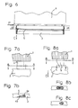
- Figure 5 shows a modified embodiment in which two relatively narrow web sections 3 are provided.
- the "loop formation" described above occurs when the closure is opened at the two points C1 and C2 between the two web sections Insert 3a and 3b.
- the connecting webs 4 are directed towards the two points P1 and P2 analogously to the exemplary embodiment according to FIGS. 1 to 4, with their tapering sides, so that the cracking process can be reliably initiated there.
- FIG. 6 shows an exemplary embodiment of a closure cap 1 in which the distance a2 from the apex of the bead 5 to the upper edge of the guarantee band in the region of the point P is smaller than the distance a1 on the opposite side. Accordingly, in the area of the smaller distance a2, when the inner bead 5 is screwed on, the complementary bead 6 (FIG. 1) will first come into engagement on the container neck 7. The train on the guarantee tape 2 thus begins in the area of the point P, so that loops are formed in the direction of the arrow C.
- the start of the crack is determined solely by the stretching and loop formation of the guarantee band in the area of greatest weakening, i.e.
- means are provided in the exemplary embodiment according to FIG. 6 as well as in the exemplary embodiments according to FIGS. 1 to 4 in order to particularly provoke the start of the crack at a specific point. This is also achieved by cams or deeper bead formation.
- Figures 7a and 7b show the shape of the connecting webs 4 schematically and on an enlarged scale.
- the connecting webs 4 are accordingly formed with a section 4c which is approximately rectangular in cross section, which merges into a tapering section 4d in which the plastic material is particularly stretchable due to its elasticity and thus tends to yield. This stretch leads to the above described loop formation, from which the cracking process is derived directly.
- FIG. 8 shows a modified exemplary embodiment, in which the webs 4 are additionally weakened in their lower region by a notch 8. Every pull in the direction of arrow C causes the guarantee strip 2 to tip down, which causes the crack to start.
- the notch could also have a different geometric shape and e.g. be provided in the middle section of the connecting web 4, the weakening could be formed as a perforation on one side of the connecting web 4 or subsequently made as an incision.
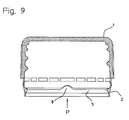
- FIG. 9 shows an exemplary embodiment of a closure cap 1 with a guarantee band 2 with an inner bead 5.
- An elevation 8 is provided on the inner bead 5, which at this point causes firmer and earlier engagement with a complementary bead 6 (FIG. 1) of a container neck 7.
- FIG. 9 shows an exemplary embodiment of a closure cap 1 with a guarantee band 2 with an inner bead 5.
- An elevation 8 is provided on the inner bead 5, which at this point causes firmer and earlier engagement with a complementary bead 6 (FIG. 1) of a container neck 7.
Abstract
Description
Die Erfindung betrifft eine Verschlusskappe aus Kunststoff mit einem Garantieband gemäss Oberbegriff von Patentanspruch 1.The invention relates to a sealing cap made of plastic with a guarantee band according to the preamble of
Derartige Verschlusskappen mit einem Garantieband, das mit einer Mehrzahl von Verbindungsstegen mit der Kappe verbunden ist, setzen sich beim Verbraucher immer mehr durch. Das Garantieband ist dabei so ausgebildet, dass es durch Schrumpfen oder durch formschlüssiges Einrasten oder durch Anformung auf entsprechenden Wulste, Nocken oder in Hinterschneidungen am Behälterhals befestigt wird. Beim erstmaligen Oeffnen der Kappe wird deshalb ein derartiger Widerstand durch das mit dem Behälterhals verbundene Garantieband aufgebaut, dass die Verbindungsstege wenigstens teilweise reissen, so dass das erstmalige Oeffnen der Verschlusskappe angezeigt wird (Tamper evidence).Such caps with a guarantee band, which is connected to the cap with a plurality of connecting webs, are becoming increasingly popular with consumers. The guarantee band is designed in such a way that it is attached to the neck of the container by shrinking or by positive locking or by molding on corresponding beads, cams or in undercuts. When the cap is opened for the first time, such a resistance is built up by the guarantee band connected to the neck of the container that the connecting webs at least partially tear, so that the first opening of the closure cap is indicated (tamper evidence).
Bei manchen Garantiebandversionen ist auch noch zusätzlich zu den Verbindungsstegen am Garantieband selbst, eine vertikale (oder mehrere vertikale) Sollbruchlinie vorgesehen. Verschlusskappen sind sowohl als Schraubkappen mit Innengewinde als auch als Schnapp-Kappen oder mit anderen Formen der Befestigung am Behälterhals (z.B. bajonett-artige Verriegelung) bekannt.In some versions of the guarantee band, a vertical (or more vertical) predetermined breaking line is also provided in addition to the connecting webs on the guarantee band itself. Sealing caps are known both as screw caps with an internal thread and as snap caps or with other forms of fastening to the container neck (e.g. bayonet-type locking).
Eine Ausführungsform einer solchen Verschlusskappe ist aus dem EP-Patent 154 603 bekannt. Dort wird ein Schraubverschluss mit einem sogenannten mechanischen Garantieband gezeigt, das beim erstmaligen Aufsetzen mit mehreren Haltenocken und einem Wulst am Garantieband über einen komplementären Wulst am Behälterhals schnappt. Das Garantieband ist einseitig mit einem Steg dauerhaft mit der Schraubkappe verbunden.An embodiment of such a closure cap is known from EP patent 154 603. There is shown a screw cap with a so-called mechanical guarantee band, which snaps over a complementary bulge on the container neck when it is first put on with several retaining cams and a bead on the guarantee band. The guarantee tape is permanently connected to the screw cap on one side with a web.
Diese Verschlusskappe gemäss EP-Patent 154 603 sowie auch die anderen Typen und Gattungen der eingangs beschriebenen Arten von Verschlusskappen lassen sich hinsichtlich ihrer Garantie-Eigenschaften weiter verbessern. Ein Problem der bekannten Verschlusskappen besteht nämlich darin, dass die Verbindungsstege einerseits ausreichend fest und belastbar sein sollen, um weder beim Handling, beim Ausstossen aus Spritzgussformen, beim Lagern in grossen Behältern oder beim Aufschrauben auf die Flasche und beim Ueberschnappen über einen Behälterwulst oder beim Warmverformen zu reissen oder beschädigt zu werden. Andererseits soll jeder Verbindungssteg aber extrem empfindlich gegen jede Art der Zugbelastung sein, um möglichst bereits zu Beginn eines erstmaligen Aufschraubens zu reissen und zuverlässig seine Garantiefunktion zu erfüllen. Diese gegensätzlichen Anforderungen lassen sich vor allem bei mechanischen Garantiebändern schwer verwirklichen. Dort wird nämlich beim Aufschrauben der Verschlusskappe eine relativ grosse Belastung auf die Verbindungsstege ausgeübt, wenn das Garantieband über den komplementären Wulst an der Flasche oder am Behälter schnappt.This closure cap according to EP patent 154 603 and also the other types and types of the types of closure caps described at the outset can be further improved with regard to their guarantee properties. A problem with the known caps is that the connecting webs should be sufficiently strong and resilient, on the one hand, to prevent them from being handled, from being ejected from injection molds, from being stored in large containers or from being screwed onto the bottle and from being snapped over a container bead or during thermoforming to tear or get damaged. On the other hand, each connecting bridge should be extremely sensitive to any type of tensile load, in order to tear as early as possible when it is first unscrewed and to reliably fulfill its guarantee function. These conflicting requirements are particularly difficult to meet with mechanical guarantee tapes. There, namely, when the cap is screwed on, a relatively large load is exerted on the connecting webs if the guarantee band snaps over the complementary bead on the bottle or the container.
Der Erfindung liegt die Aufgabe zugrunde, die Nachteile des Bekannten zu vermeiden, insbesondere also eine Verschlusskappe der vorstehend beschriebenen Arten zu schaffen, die einerseits ihre Garantiefunktion gut erfüllt, d.h. also schnell und zuverlässig beim Oeffnen reisst, und die aber andererseits ausreichende Stabilität für den gesamten Herstellungs- und Handling-Ablauf aufweist.The invention has for its object to avoid the disadvantages of the known, in particular to create a closure cap of the types described above, which on the one hand fulfills its guarantee function well, i.e. that is, it tears quickly and reliably when opened, but which, on the other hand, has sufficient stability for the entire manufacturing and handling process.
Erfindungsgemäss wird dies gemäss Kennzeichen von Patentanspruch 1 erreicht.According to the invention, this is achieved according to the characterizing part of
Ein solcher Verschluss weist erfindungsgemäss eine Mehrzahl, d.h. also wenigstens zwei, vorzugsweise jedoch wenigstens vier Verbindungsstege auf. Wenigstens zwei einer bestimmten Stelle benachbarter Stege sind an ihrer dieser Stelle zugewandten Seite geschwächt. Diese Schwächung bedeutet beim Oeffnungsvorgang z.B. grössere Reissneigung, so dass immer dann, wenn von dieser Stelle aus eine Zugbelastung auf das Garantieband ausgeübt wird, sich ein Riss quasi von der genannten Stelle weg seitlich durch die angrenzenden und nächstfolgenden Verbindungsstege fortpflanzt.According to the invention, such a closure has a plurality, that is to say at least two, but preferably at least four, connecting webs. At least two webs adjacent to a certain point are facing at this point Side weakened. During the opening process, this weakening means, for example, a greater tendency to tear, so that whenever a tensile load is exerted on the guarantee tape from this point, a crack virtually propagates laterally away from the stated point through the adjacent and subsequent connecting webs.
Vorzugsweise sollen dabei Mittel vorgesehen sein, um den Rissbeginn an einer bestimmten Stelle am Umfang des Garantiebandes zu provozieren. Dies kann z.B. dadurch erreicht werden, dass an einer Stelle der Haltenocken so ausgebildet, insbesondere erhöht oder vertieft ist, dass beim Oeffnen dort verstärkt Zugkräfte in das Garantieband eingeleitet werden. Es ist auch denkbar, das Garantieband an einer oder an mehreren Stellen fest und dauerhaft mit einer Schraubkappe zu verbinden, so dass beim Oeffnen der Verschluss gezwungen wird, auf die gegenüberliegende Seite "auszuweichen" und dort das Garantieband verstärkt zu belasten, was dann an dieser Stelle den Rissbeginn provoziert. Besonders zuverlässig lässt sich dieser Effekt erzielen, wenn die Zone der festen Verbindung zwischen Garantieband und Schraubverschluss etwa über einen Umfangswinkel von 130° bis 240° vorgesehen ist. Besonders gute Ergebnisse ergeben sich bei etwa 180° bis 210°.Means should preferably be provided to provoke the start of the crack at a certain point on the circumference of the guarantee band. This can e.g. can be achieved in that at one point the holding cams are designed, in particular raised or deepened, that tensile forces are introduced into the guarantee band there when they are opened. It is also conceivable to firmly and permanently connect the guarantee band at one or more points with a screw cap, so that when the closure is opened it is forced to "dodge" on the opposite side and there to put more strain on the guarantee band, which then affects this Make the crack start provoked. This effect can be achieved particularly reliably if the zone of the fixed connection between the guarantee band and the screw closure is provided over a circumferential angle of 130 ° to 240 °. Particularly good results are obtained at around 180 ° to 210 °.
Alternativ ist demnach denkbar, das Garantieband quasi in zwei oder drei Abschnitte zu unterteilen, von denen jeder mittels eines festen Stegs dauerhaft mit der Schraubkappe verbunden ist und dann durch entsprechende Massnahmen in den durch die festen Stege begrenzten Segmenten Punkte mit vorbestimmtem Rissbeginn vorzusehen.Alternatively, it is therefore conceivable to divide the guarantee band into two or three sections, each of which is permanently connected to the screw cap by means of a fixed web, and then to provide points with a predetermined start of the crack in the segments delimited by the fixed webs.
Die Erfindung lässt sich technisch besonders einfach realisieren, wenn die Verbindungsstege auf die Stelle des vorgesehenen Rissbeginns zu, im Querschnitt verjüngt sind. Die Stege können also im Querschnitt z.B. "keilförmig" ausgebildet sein. "Keilförmig" erfasst dabei auch solche Konfigurationen, bei denen eine oder mehrere der Seitenflächen des Keils konkav oder konvex gekrümmt sind. Wesentlich ist jedenfalls in erster Linie, dass die der vorgesehenen Riss-Stelle abgewandte Seite des Verbindungsstegs dicker und mechanisch fester ausgebildet ist, als die der vorgesehenen Riss-Stelle zugewandte Seite, und dass meistens zwei benachbarte Stege symmetrisch auf die Riss-Stelle zu geschwächt sind. Es kann Anwendungsfälle geben, bei denen es ausreicht, die beiden der vorgesehenen Riss-Stelle unmittelbar benachbarten Verbindungsstege auf die beschriebene Weise auszubilden und die restlichen Stege in der üblichen Weise zu formen. Dies kann deshalb möglich sein, weil vor allem der Beginn des Reissens bei Garantiebändern kritisch ist. Sobald das Garantieband einmal eingerissen ist und an einer Stelle P durchhängt oder schräg zur Schraubkappe verläuft, verjüngt sich der freie Querschnitt und es verkantet sich unter dem Komplementär-Wulst an der Flaschenöffnung. Es kann dann nicht mehr - wie dies z.B. zu Beginn eines Oeffnungsvorgangs möglich wäre - parallel mit der Kappe angehoben und über einen Komplementär-Wulst oder eine Vertiefung an der Flaschenöffnung nach oben geschnappt werden.The invention can be implemented in a technically particularly simple manner if the connecting webs are tapered in cross-section to the location of the intended crack start. The cross-sections of the webs can thus be, for example, “wedge-shaped”. "Wedge-shaped" also captures such configurations in which one or more of the side surfaces of the wedge are concave or convex curved. In any case, it is essential in the first place that the side of the connecting web facing away from the intended crack location is thicker and mechanically stronger than the side facing the intended crack location, and that usually two adjacent webs are weakened symmetrically towards the crack location . There may be applications in which it is sufficient to form the two connecting webs immediately adjacent to the intended crack location in the manner described and to shape the remaining webs in the usual way. This can be possible because the start of tearing is particularly critical with guarantee tapes. As soon as the guarantee band is torn and sags at a point P or runs diagonally to the screw cap, the free cross-section tapers and it jams under the complementary bead at the bottle opening. It can then no longer be raised in parallel with the cap, as would be possible, for example, at the beginning of an opening process, and snapped upwards via a complementary bead or a depression in the bottle opening.
Wenn der Querschnitt der Verbindungsstege etwa keilförmig ist, ist ein Keilwinkel von etwa 15° bis 30° und vorzugsweise etwa 20° besonders geeignet für die Erfindung. Es hat sich gezeigt dass, Keilspitzen mit diesem Winkel relativ schnell bei Zugbelastung einreissen, während die verdickte, der Reisstelle abewandte Seite ausreichend stabil ist, um die Manipulation und das Handling der Schraubkappe vor dem Aufsetzen und beim Aufsetzen ohne Bruch der Verbindungsstege zu gewährleisten.If the cross section of the connecting webs is approximately wedge-shaped, a wedge angle of approximately 15 ° to 30 ° and preferably approximately 20 ° is particularly suitable for the invention. It has been shown that wedge tips with this angle tear relatively quickly under tensile load, while the thickened side facing away from the rice pad is sufficiently stable to ensure manipulation and handling of the screw cap before putting on and when putting on without breaking the connecting webs.
Der Verbindungssteg kann aber auch auf andere Weise geschwächt sein und z.B. horizontal eingeschnitten oder mit einer oder mehreren Kerben versehen sein.However, the connecting web can also be weakened in another way and, for example, cut horizontally or provided with one or more notches.
Die Erfindung ist im folgenden in Ausführungsbeispielen anhand der Zeichnungen näher erläutert. Es zeigen:
Figur 1- die schematische Darstellung eines Querschnitts durch einen Verschluss mit den Merkmalen der Erfindung,
Figur 2- eine Ansicht von unten auf den Verschluss gemäss
Figur 1, - Figur 3a
- ein Schnitt längs der Linie A-A gemäss
Figur 1 in vergrössertem Massstab und im Ausschnitt, Figur 3b- eine Ansicht der Darstellung gemäss Figur 3A,
Figur 4- eine Verschlusskappe mit Schraubgewinde im Moment des Abschraubens von einer Getränkeflasche,
- Figur 5a
- ein abgewandeltes Ausführungsbeispiel eines Schraubverschlusses mit zwei dauerhaften Verbindungsstegen,
Figur 6- die schematische Darstellung eines Verschlusses mit mechanischem Garantieband,
- Figur 7 a
- und
- Figur 7b
- schematische Darstellung eines Verbindungsstegs mit keilförmig zulaufender Spitze,
- Figur 8a
- und
- Figur 8b
- das abgewandelte Ausführungsbeispiel eines Verbindungsstegs, sowie
- Figur 9
- ein weiter abgewandeltes Ausführungsbeispiel mit Verschlusskappe.
- Figure 1
- the schematic representation of a cross section through a closure with the features of the invention,
- Figure 2
- 2 shows a view from below of the closure according to FIG. 1,
- Figure 3a
- 2 shows a section along the line AA according to FIG. 1 on an enlarged scale and in the detail,
- Figure 3b
- 3 shows a view of the illustration according to FIG. 3A,
- Figure 4
- a cap with screw thread when unscrewing from a beverage bottle,
- Figure 5a
- a modified embodiment of a screw cap with two permanent connecting webs,
- Figure 6
- the schematic representation of a closure with a mechanical guarantee band,
- Figure 7 a
- and
- Figure 7b
- schematic representation of a connecting web with a tapered tip,
- Figure 8a
- and
- Figure 8b
- the modified embodiment of a connecting web, and
- Figure 9
- a further modified embodiment with a cap.
Gemäss Figur 1 und 2 ist eine im Spritzgussverfahren hergestellte Verschlusskappe 1 mit einem Garantieband 2 versehen. Ueber einen Umfangswinkel Alpha von ca. 210° ist die Verschlusskappe 1 mit dem Garantieband 2 mittels eines Steg-Abschnitts 3 dauerhaft verbunden. Im Bereich des restlichen Umfangwinkels ist dagegen das Garantieband 2 durch fünf Verbindungsstege 4 verbunden.According to FIGS. 1 and 2, a
Das Garantieband 2 weist auf seiner Innenseite einen umlaufenden Wulst 5 auf, mit welchem das Garantieband 2 unter einem komplementären Wulst 6 an einer Getränkeflasche einrasten kann. Der Wulst 5 läuft unter einem spitzen Winkel nach unten aus, so dass das Garantieband 2 beim Aufschrauben auf die Flasche langsam gedehnt und über den komplementären Wulst 6 am Flaschenhals geschnappt werden kann.The
Da das Garantieband 2 auch im Bereich des Steg-Abschnitts 3 mit dem Wulst 5 versehen ist, wird beim erstmaligen Oeffnen auf der dem Steg-Abschnitt 3 gegenüberliegenden Seite etwa in Richtung des Pfeils A eine verstärkte Zugspannung ausgeübt. Dies resultiert daraus, dass beim Abschrauben der Wulst 5 im Bereich der Abreissstege infolge der Vergrösserung des Wulstes in diesem Bereich verstärkt in Eingriff mit dem komplementären Wulst 6 am Flaschenhals 7 kommt. Ausserdem wird der Wulst 5 im Stegbereich 3 vom Behälterhals weg in Richtung des Pfeils B gemäss Figur 1 gedrückt, wodurch er auf der gegenüberliegenden Seite fester in Eingriff kommt und dadurch zuverlässig zu Beginn des Oeffnens reisst. Das Reissen der Verbindungsstege 4 wird deshalb besonders im Bereich zwischen den beiden Verbindungsstegen 4a und 4b provoziert.Since the
Wie aus Figur 2 und 3 besonders gut ersichtlich ist, sind die Stege 4 etwa keilförmig ausgebildet, wobei sämtliche Stege mit ihrer Keilspitze, d.h. also ihrer dünneren und schwächeren Kante auf den Punkt P zugerichtet sind, wo der Reissvorgang einsetzen soll.As can be seen particularly well from FIGS. 2 and 3, the
Wie aus Figur 3b besonders gut ersichtlich ist, bildet das Garantieband 2 nach dem Beginn des Reissvorgangs eine nach unten durchhängende "Schlaufe", weil sich der Verschluss etwas auf dem Flaschenhals 7 verkantet. Sobald diese Stellung erreicht ist, pflanzt sich der Reissvorgang ausgehend vom Punkt P schnell über die anderen Stege 4 fort, wenn die Verschlusskappe 1 weiter geöffnet wird. Diese Schlaufenbildung in Richtung des Pfeils C ist auch besonders gut aus Figur 4 ersichtlich.As can be seen particularly well from FIG. 3b, the
Die sich in Richtung des Punkts P verjüngenden Verbindungsstege 4 sind auf jeder dem Punkt P abgewandten Seite mit einem verdickten Abschnitt versehen, der sicher stellt, dass das Garantieband 2 beim Handling oder auch beim Herstellen, insbesondere beim Ausstossen aus einem Spritzgusswerkzeug, nicht beschädigt wird und dass insbesondere die Verbindungsstege 4 dabei nicht brechen oder reissen.The connecting
Selbstverständlich kann der Querschnitt des Garantiebandes auch abgewandelt werden, so kann z.B. die Verjüngung zur "Keilspitze" je nach verwendetem Kunststoffmaterial und Behälter- bzw. Verschlusskonfiguration spitzer oder stumpfer ausgebildet sein. Auch die Dicke und die Gesamtlänge der Stege 4 sowie die Breite des verstärkten, dem Punkt B abgewandten Endes kann den speziellen Gegebenheiten insbesondere der Reissfestigkeit des verwendeten Kunststoffs und der Belastbarkeit der Verbindung zwischen Garantieband und Behälter angepasst werden.Of course, the cross section of the guarantee band can also be modified, e.g. the taper to the "wedge tip" may be pointed or blunt, depending on the plastic material used and the container or closure configuration. The thickness and the total length of the
Auch die Länge des Steg-Abschnitts 3 lässt sich ersichtlicherweise durch einfache Versuche optimieren. So haben sich z.B. bei Umfangswinkeln Alpha von 170° bis 210° sehr gute Ergebnisse erzielen lassen.The length of the
Figur 4 zeigt ein Ausführungsbeispiel, bei welchem ein warm anformbares Garantieband 2 durch Anpressen oder Schrumpfen in bekannter Weise unterhalb eines Wulstes 6 am Behälter nach 7 verjüngt und angeformt wurde. Die Querschnittsform der Verbindungsstege 4 entspricht dem Ausführungsbeispiel gemäss Figur 1 bis 3.FIG. 4 shows an exemplary embodiment in which a heat-
Figur 5 zeigt ein abgewandeltes Ausführungsbeispiel, bei welchem zwei relativ schmale Steg-Abschnitte 3 vorgesehen sind. In diesem Fall wird die vorstehend beschriebene "Schlaufenbildung" beim Oeffnen des Verschlusses an den beiden Punkten C1 und C2 zwischen den beiden Steg-Abschnitten 3a und 3b einsetzen.Figure 5 shows a modified embodiment in which two relatively
Aus diesem Grund sind die Verbindungsstege 4 analog dem Ausführungsbeispiel gemäss Figur 1 bis 4 mit deren spitz zulaufenden Seiten auf die beiden Punkte P1 und P2 zu gerichtet, so dass dort der Rissvorgang zuverlässig eingeleitet werden kann.For this reason, the connecting
Figur 6 zeigt ein Ausführungsbeispiel einer Verschlusskappe 1 bei welchem der Abstand a2 des Scheitelpunkts des Wulstes 5 zur Oberkannte des Garantiebands im Bereich des Punktes P kleiner ist als der Abstand al auf der gegenüberliegenden Seite. Dementsprechend wird im Bereich des kleineren Abstands a2 beim Aufschrauben der Innenwulst 5 zuerst mit dem komplementären Wulst 6 (Figur 1) am Behälterhals 7 in Eingriff kommen. Der Zug auf das Garantieband 2 setzt also im Bereich des Punkts P ein, so dass sich Schlaufenbildung in Richtung des Pfeils C ergibt.FIG. 6 shows an exemplary embodiment of a
Während also beim Ausführungsbeispiel gemäss Figur 5 der Rissbeginn allein dadurch bestimmt wird, dass die Dehnung und Schlaufenbildung des Garantiebands im Bereich der grössten Schwächung, d.h. also bei den Punkten P1 und P2 beginnt, sind beim Ausführungsbeispiel gemäss Figur 6 wie auch bei den Ausführungsbeispielen gemäss Figur 1 bis 4 Mittel vorgesehen, um den Rissbeginn an einem bestimmten Punkt besonders zu provozieren. Dies wird auch durch Nocken oder tiefere Wulstausbildung erreicht.Thus, while in the exemplary embodiment according to FIG. 5 the start of the crack is determined solely by the stretching and loop formation of the guarantee band in the area of greatest weakening, i.e. Thus, starting at points P1 and P2, means are provided in the exemplary embodiment according to FIG. 6 as well as in the exemplary embodiments according to FIGS. 1 to 4 in order to particularly provoke the start of the crack at a specific point. This is also achieved by cams or deeper bead formation.
Figur 7a und 7b zeigen die Form der Verbindungsstege 4 schematisch und in vergrössertem Massstab. Die Verbindungsstege 4 sind demnach mit einem im Querschnitt etwa rechteckigen Abschnitt 4c ausgebildet, der in einen spitz zulaufenden Abschnitt 4d übergeht, in welchem das Kunststoffmaterial schon aufgrund seiner Elastizität besonders dehnfähig ist und damit zum Nachgeben neigt. Diese Dehnung führt zur vorstehend beschriebenen Schlaufenbildung, aus welcher sich unmittelbar der Rissvorgang herleitet.Figures 7a and 7b show the shape of the connecting
Figur 8 zeigt ein abgewandeltes Ausführungsbeispiel, bei welchem die Stege 4 in ihrem unteren Bereich zusätzlich durch eine Einkerbung 8 geschwächt sind. Jeder Zug in Richtung des Pfeils C lässt das Garantieband 2 nach unten kippen, wodurch der Rissbeginn einsetzt.FIG. 8 shows a modified exemplary embodiment, in which the
Selbstverständlich könnte die Einkerbung auch eine andere geometrische Form haben und z.B. in mittlerem Abschnitt des Verbindungsstegs 4 vorgesehen sein, die Schwächung könnte als Perforation auf einer Seite des Verbindungsstegs 4 ausgebildet oder auch nachträglich als Einschnitt angebracht werden. Vor allem ist wichtig, dass wenigstens zwei der Verbindungsstege 4 an ihren aufeinander zugerichteten Seiten derart geschwächt sind, dass bei Beginn des Aufschraubvorgangs dort eine verstärkte Dehnung einsetzt und Schlaufenbildung des Garantiebands ermöglicht wird.Of course, the notch could also have a different geometric shape and e.g. be provided in the middle section of the connecting
Figur 9 zeigt ein Ausführungsbeispiel einer Verschlusskappe 1 mit Garantieband 2 mit Innen-Wulst 5. Auf dem Innenwulst 5 ist eine Erhöhung 8 vorgesehen, die an dieser Stelle festeren und früheren Eingriff mit einem komplementären Wulst 6 (Figur 1) eines Behälterhalses 7 bewirkt. Beim Oeffnen der Verschlusskappe setzt also im Bereich der Erhöhung 8 die Zugspannung auf das Garantieband 2 ein, womit dort der Punkt P der vorgesehenen Rissbildung vorbestimmt wird.FIG. 9 shows an exemplary embodiment of a
Claims (9)
- A closure cap of plastics material having a guarantee strip (2) which is intended to be brought into engagement with one or more retaining elements (6) on a container neck (7), wherein the closure cap (1) and the guarantee strip (2) are connected by a plurality of connecting web portions (4) which break or tear when the bottle is first opened, characterised in that the web portions (4a, 4b) in the area around at least one selected location (P) of the guarantee strip, which location is particularly loaded when the container is opened for the first time, are particularly weakened by the web portion cross-section being weaker, that is to say more sensitive to beginning tearing, at one side at its side which is towards said location (P), than at its side which is remote from said location (P).
- A closure cap according to claim 1 characterised in that there are provided means for defining the location of the beginning of tearing at the periphery of the guarantee strip (2) and that at least the connecting web portions (4a, 4b) which are adjacent to the location (P) of the intended beginning of tearing are of a cross-section which is weakened at its side towards the location (P) of the beginning of tearing.
- A closure cap according to claim 1 or claim 2 characterised in that the cross-section of the connecting web portions (4) decreases towards the location (P) of the intended beginning of tearing.
- A closure cap according to one of claims 1 to 3 characterised in that the connecting web portions (4) are approximately wedge-shaped in cross-section, the tip of the wedge configuration being towards the location (P) of the beginning of tearing.
- A closure cap according to one of the preceding claims characterised in that, as the means for defining the location (P) of the intended beginning of tearing, the closure band is provided at a side of the guarantee strip which is approximately opposite the location (P) of the beginning of tearing with a web section (3) which extends over a given angular region and which fixedly connects the guarantee strip (2) to the closure (1).
- A closure cap according to claim 5 characterised in that there are provided at least two web sections (3).
- A closure cap according to one of preceding claims 3 to 6 characterised in that the angle of narrowing or the wedge angle of the web portion or portions (4) is about 15° to 30°.
- A closure cap according to claim 7 characterised in that the angle is about 20°.
- A closure cap according to one of the preceding claims characterised in that the web section (3) with which the guarantee strip (2) is fixedly connected to the closure cap (1) extends over a peripheral angle of 130° - 240° and preferably 180° - 210°.
Applications Claiming Priority (2)
| Application Number | Priority Date | Filing Date | Title |
|---|---|---|---|
| CH1133/90 | 1990-04-04 | ||
| CH113390 | 1990-04-04 |
Publications (2)
| Publication Number | Publication Date |
|---|---|
| EP0451102A1 EP0451102A1 (en) | 1991-10-09 |
| EP0451102B1 true EP0451102B1 (en) | 1993-10-06 |
Family
ID=4203269
Family Applications (1)
| Application Number | Title | Priority Date | Filing Date |
|---|---|---|---|
| EP91810216A Expired - Lifetime EP0451102B1 (en) | 1990-04-04 | 1991-03-26 | Plastic closure |
Country Status (7)
| Country | Link |
|---|---|
| US (1) | US5074425A (en) |
| EP (1) | EP0451102B1 (en) |
| AT (1) | ATE95488T1 (en) |
| CA (1) | CA2039619A1 (en) |
| DE (1) | DE59100444D1 (en) |
| DK (1) | DK0451102T3 (en) |
| ES (1) | ES2044711T3 (en) |
Cited By (1)
| Publication number | Priority date | Publication date | Assignee | Title |
|---|---|---|---|---|
| EP0965533A1 (en) | 1998-06-18 | 1999-12-22 | Mouldtec Kunststoff GmbH | Closure cap, in particular plastic screw cap with a tamper evident band |
Families Citing this family (12)
| Publication number | Priority date | Publication date | Assignee | Title |
|---|---|---|---|---|
| GB9205374D0 (en) * | 1992-03-12 | 1992-04-22 | Metal Closures Group Ltd | Container closures |
| DE4211992A1 (en) * | 1992-04-09 | 1993-10-14 | Mouldtec Pvg Ag Meilen | Bottle cap with locking ring |
| US5405032A (en) * | 1992-11-06 | 1995-04-11 | Crown Cork & Seal Company, Inc. | Tamper indicating closure and method and device for the manufacture of a tamper-indicating closure |
| IT1274907B (en) * | 1994-09-20 | 1997-07-25 | Pelliconi Abruzzo Srl | PLASTIC CAPSULE WITH WARRANTY CLAMP. |
| US5501349A (en) * | 1994-10-27 | 1996-03-26 | H-C Industries, Inc. | Tamper-indicating plastic closure with selectively strengthened pilfer band |
| US6491175B1 (en) * | 2000-06-28 | 2002-12-10 | Saad Taha | Single piece closure for a pressurized container |
| CA2494897A1 (en) * | 2002-08-07 | 2004-02-19 | Silgan Closures, Llc | Reduced application energy closure |
| WO2005012129A1 (en) * | 2003-08-01 | 2005-02-10 | Liqui-Box Canada Inc. | Tamper evident fitment assembly |
| ES1299941U (en) * | 2018-04-26 | 2023-05-24 | Obrist Closures Switzerland | CLOSING (Machine-translation by Google Translate, not legally binding) |
| US20220153483A1 (en) * | 2019-03-11 | 2022-05-19 | Alpla Werke Alwin Lehner Gmbh & Co. Kg | Container closure |
| FR3104144B1 (en) * | 2019-12-04 | 2021-12-03 | Soc Lorraine De Capsules Metalliques Manufacture De Bouchage | Screw closure device intended to remain attached to a container after opening the container. |
| US20220041339A1 (en) * | 2020-08-07 | 2022-02-10 | Niagara Bottling, Llc | Single anchor closure |
Family Cites Families (6)
| Publication number | Priority date | Publication date | Assignee | Title |
|---|---|---|---|---|
| US4432461A (en) * | 1982-04-09 | 1984-02-21 | Owens-Illinois, Inc. | Tamper indicating package |
| DE3377637D1 (en) * | 1982-05-06 | 1988-09-15 | Anchor Hocking Corp | Tamperproof beverage closure |
| GB2191766A (en) * | 1986-06-17 | 1987-12-23 | Grace W R & Co | Screw container with tamper-evident feature |
| CH671205A5 (en) * | 1987-02-26 | 1989-08-15 | Crown Cork Ag | |
| US4923073A (en) * | 1989-01-30 | 1990-05-08 | H-C Industries, Inc. | Tamper-indicating plastic closure |
| US4967920A (en) * | 1989-06-26 | 1990-11-06 | Continental White Cap, Inc. | Partial tamper band |
-
1991
- 1991-03-26 AT AT91810216T patent/ATE95488T1/en not_active IP Right Cessation
- 1991-03-26 DK DK91810216.1T patent/DK0451102T3/en active
- 1991-03-26 EP EP91810216A patent/EP0451102B1/en not_active Expired - Lifetime
- 1991-03-26 DE DE91810216T patent/DE59100444D1/en not_active Expired - Fee Related
- 1991-03-26 ES ES91810216T patent/ES2044711T3/en not_active Expired - Lifetime
- 1991-04-03 CA CA002039619A patent/CA2039619A1/en not_active Abandoned
- 1991-04-04 US US07/680,299 patent/US5074425A/en not_active Expired - Fee Related
Cited By (1)
| Publication number | Priority date | Publication date | Assignee | Title |
|---|---|---|---|---|
| EP0965533A1 (en) | 1998-06-18 | 1999-12-22 | Mouldtec Kunststoff GmbH | Closure cap, in particular plastic screw cap with a tamper evident band |
Also Published As
| Publication number | Publication date |
|---|---|
| EP0451102A1 (en) | 1991-10-09 |
| DK0451102T3 (en) | 1993-11-22 |
| ES2044711T3 (en) | 1994-01-01 |
| US5074425A (en) | 1991-12-24 |
| ATE95488T1 (en) | 1993-10-15 |
| CA2039619A1 (en) | 1991-10-05 |
| DE59100444D1 (en) | 1993-11-11 |
Similar Documents
| Publication | Publication Date | Title |
|---|---|---|
| EP0810952B1 (en) | Closure cap with retaining strip | |
| EP0593396B1 (en) | Tamper proof plastic closure | |
| DE2910178C2 (en) | Tamper-evident screw cap for bottles and the like | |
| EP0714369B1 (en) | Screw cap with warranty strip | |
| EP0451102B1 (en) | Plastic closure | |
| WO1996000171A1 (en) | Closure cap with warranty ring | |
| DE4128282A1 (en) | LOCKING WITH TOWED TAPE AND Pawl TOOTH DRIVE AND WITHOUT PROTECTION INDICATOR | |
| DE10207204A1 (en) | Combination of a bottle with a snap-on adapter and / or a cap | |
| EP0254673A1 (en) | Container closure provided with a tamper indicating band | |
| DE10146817A1 (en) | screw | |
| EP0281514A1 (en) | Closure cap with a warranty strap | |
| EP0460557B1 (en) | Screw-cap with tamper-evident band | |
| DE2753080C2 (en) | Closing cap with tamper evident | |
| EP0951428B1 (en) | Plastics screw-type cap for bottles, provided with a tamperproof strip | |
| DE3912137A1 (en) | Screw cap for bottle - is torn along line of ribs when opened and this indicates if cap has been removed | |
| EP3938290A1 (en) | Container closure | |
| DE3727887C2 (en) | ||
| DE4317269C1 (en) | Tamper-indicating securing device for container closures | |
| EP0886605B1 (en) | Tamper-indicating, plastic protective cap | |
| EP0886606B1 (en) | Container opening and cap | |
| EP0891929B1 (en) | Screw closure with tamper indicating band | |
| EP0965533A1 (en) | Closure cap, in particular plastic screw cap with a tamper evident band | |
| DE10024072C1 (en) | Plastic cap, especially screw cap, with a guarantee band | |
| EP0912412A1 (en) | Screw cap | |
| EP0673849A1 (en) | Tube closure made of plastic |
Legal Events
| Date | Code | Title | Description |
|---|---|---|---|
| PUAI | Public reference made under article 153(3) epc to a published international application that has entered the european phase |
Free format text: ORIGINAL CODE: 0009012 |
|
| AK | Designated contracting states |
Kind code of ref document: A1 Designated state(s): AT BE CH DE DK ES FR GB IT LI NL SE |
|
| 17P | Request for examination filed |
Effective date: 19920210 |
|
| 17Q | First examination report despatched |
Effective date: 19921007 |
|
| GRAA | (expected) grant |
Free format text: ORIGINAL CODE: 0009210 |
|
| ITF | It: translation for a ep patent filed |
Owner name: LENZI & C. |
|
| AK | Designated contracting states |
Kind code of ref document: B1 Designated state(s): AT BE CH DE DK ES FR GB IT LI NL SE |
|
| REF | Corresponds to: |
Ref document number: 95488 Country of ref document: AT Date of ref document: 19931015 Kind code of ref document: T |
|
| REF | Corresponds to: |
Ref document number: 59100444 Country of ref document: DE Date of ref document: 19931111 |
|
| REG | Reference to a national code |
Ref country code: DK Ref legal event code: T3 |
|
| REG | Reference to a national code |
Ref country code: ES Ref legal event code: FG2A Ref document number: 2044711 Country of ref document: ES Kind code of ref document: T3 |
|
| GBT | Gb: translation of ep patent filed (gb section 77(6)(a)/1977) |
Effective date: 19931202 |
|
| ET | Fr: translation filed | ||
| ITTA | It: last paid annual fee | ||
| PLBE | No opposition filed within time limit |
Free format text: ORIGINAL CODE: 0009261 |
|
| STAA | Information on the status of an ep patent application or granted ep patent |
Free format text: STATUS: NO OPPOSITION FILED WITHIN TIME LIMIT |
|
| 26N | No opposition filed | ||
| EAL | Se: european patent in force in sweden |
Ref document number: 91810216.1 |
|
| PGFP | Annual fee paid to national office [announced via postgrant information from national office to epo] |
Ref country code: DK Payment date: 19980210 Year of fee payment: 8 |
|
| PGFP | Annual fee paid to national office [announced via postgrant information from national office to epo] |
Ref country code: SE Payment date: 19980217 Year of fee payment: 8 |
|
| PGFP | Annual fee paid to national office [announced via postgrant information from national office to epo] |
Ref country code: NL Payment date: 19980228 Year of fee payment: 8 |
|
| PG25 | Lapsed in a contracting state [announced via postgrant information from national office to epo] |
Ref country code: SE Free format text: LAPSE BECAUSE OF NON-PAYMENT OF DUE FEES Effective date: 19990327 |
|
| PG25 | Lapsed in a contracting state [announced via postgrant information from national office to epo] |
Ref country code: DK Free format text: LAPSE BECAUSE OF NON-PAYMENT OF DUE FEES Effective date: 19990331 |
|
| PG25 | Lapsed in a contracting state [announced via postgrant information from national office to epo] |
Ref country code: NL Free format text: LAPSE BECAUSE OF NON-PAYMENT OF DUE FEES Effective date: 19991001 |
|
| EUG | Se: european patent has lapsed |
Ref document number: 91810216.1 |
|
| NLV4 | Nl: lapsed or anulled due to non-payment of the annual fee |
Effective date: 19991001 |
|
| EUG | Se: european patent has lapsed |
Ref document number: 91810216.1 |
|
| REG | Reference to a national code |
Ref country code: DK Ref legal event code: EBP |
|
| PGFP | Annual fee paid to national office [announced via postgrant information from national office to epo] |
Ref country code: FR Payment date: 20010208 Year of fee payment: 11 |
|
| PGFP | Annual fee paid to national office [announced via postgrant information from national office to epo] |
Ref country code: GB Payment date: 20010219 Year of fee payment: 11 |
|
| PGFP | Annual fee paid to national office [announced via postgrant information from national office to epo] |
Ref country code: ES Payment date: 20010308 Year of fee payment: 11 |
|
| REG | Reference to a national code |
Ref country code: GB Ref legal event code: IF02 |
|
| PG25 | Lapsed in a contracting state [announced via postgrant information from national office to epo] |
Ref country code: GB Free format text: LAPSE BECAUSE OF NON-PAYMENT OF DUE FEES Effective date: 20020326 |
|
| PG25 | Lapsed in a contracting state [announced via postgrant information from national office to epo] |
Ref country code: ES Free format text: LAPSE BECAUSE OF NON-PAYMENT OF DUE FEES Effective date: 20020327 |
|
| GBPC | Gb: european patent ceased through non-payment of renewal fee |
Effective date: 20020326 |
|
| PG25 | Lapsed in a contracting state [announced via postgrant information from national office to epo] |
Ref country code: FR Free format text: LAPSE BECAUSE OF NON-PAYMENT OF DUE FEES Effective date: 20021129 |
|
| REG | Reference to a national code |
Ref country code: FR Ref legal event code: ST |
|
| REG | Reference to a national code |
Ref country code: ES Ref legal event code: FD2A Effective date: 20030410 |
|
| PGFP | Annual fee paid to national office [announced via postgrant information from national office to epo] |
Ref country code: AT Payment date: 20050208 Year of fee payment: 15 |
|
| PGFP | Annual fee paid to national office [announced via postgrant information from national office to epo] |
Ref country code: CH Payment date: 20050211 Year of fee payment: 15 |
|
| PGFP | Annual fee paid to national office [announced via postgrant information from national office to epo] |
Ref country code: DE Payment date: 20050216 Year of fee payment: 15 |
|
| PGFP | Annual fee paid to national office [announced via postgrant information from national office to epo] |
Ref country code: BE Payment date: 20050311 Year of fee payment: 15 |
|
| PG25 | Lapsed in a contracting state [announced via postgrant information from national office to epo] |
Ref country code: IT Free format text: LAPSE BECAUSE OF NON-PAYMENT OF DUE FEES;WARNING: LAPSES OF ITALIAN PATENTS WITH EFFECTIVE DATE BEFORE 2007 MAY HAVE OCCURRED AT ANY TIME BEFORE 2007. THE CORRECT EFFECTIVE DATE MAY BE DIFFERENT FROM THE ONE RECORDED. Effective date: 20050326 |
|
| PG25 | Lapsed in a contracting state [announced via postgrant information from national office to epo] |
Ref country code: AT Free format text: LAPSE BECAUSE OF NON-PAYMENT OF DUE FEES Effective date: 20060326 |
|
| PG25 | Lapsed in a contracting state [announced via postgrant information from national office to epo] |
Ref country code: LI Free format text: LAPSE BECAUSE OF NON-PAYMENT OF DUE FEES Effective date: 20060331 Ref country code: CH Free format text: LAPSE BECAUSE OF NON-PAYMENT OF DUE FEES Effective date: 20060331 Ref country code: BE Free format text: LAPSE BECAUSE OF NON-PAYMENT OF DUE FEES Effective date: 20060331 |
|
| PG25 | Lapsed in a contracting state [announced via postgrant information from national office to epo] |
Ref country code: DE Free format text: LAPSE BECAUSE OF NON-PAYMENT OF DUE FEES Effective date: 20061003 |
|
| REG | Reference to a national code |
Ref country code: CH Ref legal event code: PL |
|
| BERE | Be: lapsed |
Owner name: *CROWN CORK A.G. Effective date: 20060331 |