EP0593396B1 - Tamper proof plastic closure - Google Patents
Tamper proof plastic closure Download PDFInfo
- Publication number
- EP0593396B1 EP0593396B1 EP93810706A EP93810706A EP0593396B1 EP 0593396 B1 EP0593396 B1 EP 0593396B1 EP 93810706 A EP93810706 A EP 93810706A EP 93810706 A EP93810706 A EP 93810706A EP 0593396 B1 EP0593396 B1 EP 0593396B1
- Authority
- EP
- European Patent Office
- Prior art keywords
- guarantee
- locking elements
- closure cap
- locking
- cap according
- Prior art date
- Legal status (The legal status is an assumption and is not a legal conclusion. Google has not performed a legal analysis and makes no representation as to the accuracy of the status listed.)
- Expired - Lifetime
Links
- 239000004033 plastic Substances 0.000 title claims description 7
- 229920003023 plastic Polymers 0.000 title claims description 7
- 239000000463 material Substances 0.000 claims description 10
- 230000000903 blocking effect Effects 0.000 description 9
- 238000007789 sealing Methods 0.000 description 5
- 238000004519 manufacturing process Methods 0.000 description 4
- 239000011324 bead Substances 0.000 description 3
- 235000013361 beverage Nutrition 0.000 description 3
- 238000000034 method Methods 0.000 description 3
- 210000002105 tongue Anatomy 0.000 description 3
- 238000001746 injection moulding Methods 0.000 description 2
- 230000014759 maintenance of location Effects 0.000 description 2
- -1 polyethylene Polymers 0.000 description 2
- 239000004698 Polyethylene Substances 0.000 description 1
- 239000004743 Polypropylene Substances 0.000 description 1
- 238000000748 compression moulding Methods 0.000 description 1
- 239000000109 continuous material Substances 0.000 description 1
- 239000011521 glass Substances 0.000 description 1
- 238000002347 injection Methods 0.000 description 1
- 239000007924 injection Substances 0.000 description 1
- 230000001788 irregular Effects 0.000 description 1
- 238000012986 modification Methods 0.000 description 1
- 230000004048 modification Effects 0.000 description 1
- 229920000573 polyethylene Polymers 0.000 description 1
- 229920001155 polypropylene Polymers 0.000 description 1
Images


Classifications
-
- B—PERFORMING OPERATIONS; TRANSPORTING
- B65—CONVEYING; PACKING; STORING; HANDLING THIN OR FILAMENTARY MATERIAL
- B65D—CONTAINERS FOR STORAGE OR TRANSPORT OF ARTICLES OR MATERIALS, e.g. BAGS, BARRELS, BOTTLES, BOXES, CANS, CARTONS, CRATES, DRUMS, JARS, TANKS, HOPPERS, FORWARDING CONTAINERS; ACCESSORIES, CLOSURES, OR FITTINGS THEREFOR; PACKAGING ELEMENTS; PACKAGES
- B65D41/00—Caps, e.g. crown caps or crown seals, i.e. members having parts arranged for engagement with the external periphery of a neck or wall defining a pouring opening or discharge aperture; Protective cap-like covers for closure members, e.g. decorative covers of metal foil or paper
- B65D41/32—Caps or cap-like covers with lines of weakness, tearing-strips, tags, or like opening or removal devices, e.g. to facilitate formation of pouring openings
- B65D41/34—Threaded or like caps or cap-like covers provided with tamper elements formed in, or attached to, the closure skirt
- B65D41/3423—Threaded or like caps or cap-like covers provided with tamper elements formed in, or attached to, the closure skirt with flexible tabs, or elements rotated from a non-engaging to an engaging position, formed on the tamper element or in the closure skirt
- B65D41/3428—Threaded or like caps or cap-like covers provided with tamper elements formed in, or attached to, the closure skirt with flexible tabs, or elements rotated from a non-engaging to an engaging position, formed on the tamper element or in the closure skirt the tamper element being integrally connected to the closure by means of bridges
Definitions
- the invention relates to a guarantee closure cap made of plastic for a container, on the container neck of which at least one radially outwardly projecting blocking surface is provided, according to the preamble of claim 1.
- the guarantee function of such closures is that when the closure cap is removed for the first time, a guarantee band is torn or at least partially is torn down. The tearing or tearing off indicates to the consumer that the container has already been opened.
- the guarantee band can completely surround the container neck or extend only over part of the circumference.
- the dividing lines at which the guarantee tape tears or tears can be horizontal, i.e. run parallel to the cap base as well as vertically. E.g. it can be provided that the guarantee tape can be torn off as a complete ring from the closure cap and remains on the neck of the container. In other cases, it is desirable that the guarantee tape or the torn-off parts of the guarantee tape get caught on the sealing cap. All of these embodiments encompass the present invention.
- the containers to be closed can be glass or plastic beverage bottles. It can also be other containers, e.g. Canned jars, wide-mouth containers and the like.
- a bead is provided on the neck of the container, the underside of which forms the blocking surface with which the guarantee band of the closure cap comes into engagement.
- the invention is not limited to such circumferential beads.
- individual, segment-like cams or other retaining elements can also be used or depressions can also be provided in the neck of the container without departing from the scope of the invention. It is only important that there is an outwardly protruding locking surface that is straight, curved, regular or irregular, engages with a locking element on the sealing cap or on the guarantee band when the sealing cap is put on, in order to prevent the sealing cap from being unscrewed can be damaged without damaging the predetermined breaking points.
- such caps have a single-start or multi-start thread.
- closure caps which are connected to the container neck in a different way. These include e.g. Caps with snap devices or bayonet locks.
- Such guarantee closures are e.g. known from US-PS-4,978,017, US-PS-5,090,788 or US-PS-4,784,280 and US-PS-4,635,808.
- the flaps point obliquely upwards and inwards after being put on.
- the flaps are connected to the guarantee band by a flexible connection, so that they can be pivoted around this connection point.
- the swivel range is limited at the bottom by a projection arranged below the flaps, against which the flaps rest when the container is opened.
- the disadvantage of these flaps is that they can only be pivoted upwards to a very limited extent. Even in their upper end position, in which they rest on the inner surface of the guarantee band, the flaps are still directed clearly inwards and hinder the fitting of the closure cap.
- the object of the invention is therefore to provide a guarantee closure cap of the type described above (US-A-5,107,998) for closing such containers, which on the one hand is easy to manufacture in mass production and which on the other hand reliably fulfills its guarantee function and is easy on the The neck of the container must be put on without damaging the predetermined breaking points as soon as it is put on.
- this task is solved by a guarantee cap with the features of claim 1.
- the arrangement is particularly advantageous of the locking elements proposed, which are connected to the guarantee band by at least one articulated element, and which after the guarantee closure has been placed on the container neck engage under the blocking surface and the guarantee band block at the neck of the container.
- the flaps or retaining elements themselves are designed to be elastic so that they can snap resiliently over the locking surface when they are put on
- the invention proposes the use of a practically rigid locking element which also has an elastic / resilient joint element the guarantee band is connected.
- the locking elements have an upper retaining surface with which they can be brought into engagement with the locking surface on the container neck.
- they are provided with a lower support surface which can be supported on the surface of the inner wall of the guarantee band.
- the locking elements can thus, on the one hand, deflect through the articulation elements when the guarantee closure is put on and pivot upwards, as a result of which the fitting process proceeds without any problems. If, on the other hand, the locking elements are pivoted in the opposite direction around the joint elements when the guarantee closure is opened, they are supported with the support surface on the inner wall of the guarantee band. The engagement of the locking elements with the locking surface on the container neck is fixed in such a way that it is practically impossible to open the guarantee closure without destroying the predetermined breaking points.
- the locking elements can be supported with their support surfaces either directly on the surface of the inner wall of the guarantee band or indirectly, for example by support cams or projections on the guarantee band. It is only essential that the force exerted on the locking elements when the guarantee closure is opened is conducted into the guarantee band, so that the predetermined breaking points break or tear.
- the locking elements are fastened to the joint elements in such a way that they protrude radially inwards in an intermediate position before the guarantee closure is applied to the container.
- "Radially inwards” is intended to be both an approximately horizontal position and an obliquely upward position towards the cap base or include a position inclined in the opposite direction. It is essential for the intermediate position that the locking element protrudes radially inwards from the guarantee band so that when the guarantee closure is placed on a container, the latter can pivot the locking elements upwards to the cap base and outwards to the cap jacket around the joint elements, so that the container neck can penetrate the guarantee closure without damaging the predetermined breaking points. This is possible because the locking elements move outward from the container when pivoting around the joint elements and increase the free inside diameter of the guarantee band.
- the locking elements pivoted elastically around the joint elements snap back again and are located below the locking surfaces on the container neck.
- Such an elastic or resilient deflection can be realized practically with all plastic materials customary for such closures. This applies e.g. especially for polyethylene or polypropylene.
- the locking elements are pivoted far enough upwards and outwards when pivoting into the closed position of the guarantee closure, that the container neck and the blocking surface can pass unhindered, and that after the guarantee closure is put on, the blocking elements spring under the blocking surface on the container neck or snap.
- Another essential feature of the closure according to the invention is that when the closure is first removed from the container neck, the locking elements are moved downward and radially inward through the locking surfaces.
- the radial inward pivoting obviously causes a reduction in the free inside diameter of the guarantee band, so that the locking elements continue with the locking surface or surfaces engage on the neck of the container and overlap this or these and thereby fix the guarantee tape on the neck of the container.
- the pivoting movement of the locking elements therefore causes the free inside diameter of the guarantee band to be reduced and thus fixed on the container neck.
- the guarantee closure exhibits particularly good opening and locking properties if the locking elements can be pivoted between the closed position and the open position by an angle of more than 100 °, preferably more than 140 °. Particularly with commercially available beverage bottles, particularly good results have been achieved if the swivel angle is approximately 160 ° to 180 °.
- a particularly stable locking function of the locking elements is obtained if their retaining surface forms an angle of more than 60 °, preferably of approximately 70 ° to 100 °, with the supporting surface.
- the locking elements can connect particularly securely to the locking surface on the container neck if the locking elements, viewed in plan view, have the shape of a segment of a circle, the circle of which runs coaxially with the guarantee band.
- the length and the number of these circular segments can easily be determined depending on the configuration of the container neck and the support surface. A number of about 10 to 14 locking elements have proven particularly good in the case of beverage bottles with a 28 mm diameter.
- the locking elements in the plan view also have a different shape, for example they can run in a straight line if, for example, the support surface in the plan view has the shape of a polygon.
- Flexible material bridges between the guarantee band and the locking elements are particularly suitable as a joint element.
- the material bridges can be provided over the entire length of the locking element. However, it is also conceivable to provide the material bridges only in partial areas of the locking elements, e.g. on the two outer edges or in the middle.
- the predetermined breaking points for connecting the guarantee band or individual guarantee band segments with the sealing cap or with other guarantee band segments can best be formed as material webs which are correspondingly thinly dimensioned to tear when the guarantee closure is opened.
- material webs which are correspondingly thinly dimensioned to tear when the guarantee closure is opened.
- a guarantee closure 1 has a closure cap 2, which consists of a cap base 3 and a cylindrical cap jacket 4.
- a guarantee band 6 is fastened to the closure cap 2 by means of a plurality of predetermined breaking bars 5.
- a number of locking elements 8 are arranged on the guarantee band 6 by means of material bridges acting as a joint element 7.
- the closure cap 2 is made together with the guarantee tape 6 and the locking elements 8 in one piece in a known manner in the plastic injection molding process.
- the guarantee closure could also be produced using the compression molding process or in another suitable manner.
- Warranty tapes manufactured separately are e.g. known from U.S. Patent 4,578,857.
- the locking elements 8 are in position N according to FIG. 1 and the upper illustration in FIG. 2.
- the locking element 8 arrives with threaded sections 10 and with a circumferential, annular projection 11 in engagement.
- the locking elements 8 are thereby pivoted upwards and radially outwards about the pivot element 7 as a fulcrum, so that the free inside diameter of the guarantee band 6 increases and the guarantee band 6 can reach the position shown in FIG. 3 without the projection 11 that the predetermined breaking webs 5 would be damaged.
- the locking elements 8 are directed radially inwards, it being not important in this position whether they additionally point slightly upwards or slightly downwards, since the elasticity of the joint element 7 causes them to pivot into the first closed position I is possible in any case.
- the support surfaces 12 of the locking elements 8 determine the enlarged first inner diameter D1 (FIG. 6).
- the locking elements 8 are located below the projection 11 and its locking surface 13, which faces the retaining surface 14 of the locking elements 8.
- FIGS. 4 and 6 show how the retaining surface 14 engages with the blocking surface 13 when the guarantee closure is opened, the retaining elements 8 being pivoted radially inwards and downwards into the second opening position II and thereby determining the second reduced inside diameter D2.
- the locking elements 8 thereby increase their engagement with the locking surface 13, so that the guarantee tape 6 cannot be pulled over the projection 11.
- the predetermined breaking bars 5 therefore tear.
- This configuration ensures particularly good stability of the locking elements 8 and, on the other hand, enables the locking elements to be pivoted by an angle of approximately 160 °, which is advantageous for the opening and closing function, as shown in FIG.
- Figure 7 shows a modified embodiment in which the locking elements have an approximately V-shaped cross section.
- Such a cross-sectional shape enables particularly easy and quick demolding of the guarantee closure from an axially ejecting injection molding tool.
- a support projection 6a is provided on the inner wall of the guarantee band 6, on which the support surface 12 can be supported.
- Figure 8 shows a modified embodiment in which the support surface 12 of the locking elements 8 is designed as a cam-like projection which can be supported in a corresponding recess 6b of the guarantee band 6.
- the guarantee band 6 shown in FIG. 8 is not connected to the cap jacket 4 by individual material webs 5 but by a very thin, continuous material skin 5b (over 360 °).
- Figure 9 shows a top view of the guarantee tape (from below). It can be seen from this that the joint elements 7 for fastening the locking elements 8 to the guarantee band 6 each extend over the entire length of the locking elements 8. Both the hinge elements 7 and the locking elements 8 are shaped as circular segments and run coaxially with the guarantee band 6.
- FIG. 10 shows an embodiment in which the locking elements 8 are each connected to the guarantee band 6 on both sides by a joint element 7a, 7b.
- This design allows particularly easy pivoting of the locking elements 8 when applied to a container neck.
- the blocking elements 8 in the exemplary embodiment according to FIG. 10 are straight and not designed as circular segments.
- FIG. 11 shows the schematic representation of a locking element 8, which is arranged by means of a centrally arranged, web-like articulated element 7c is connected to the guarantee band 6.
- a multiplicity of relatively narrow locking elements 8 are provided, wherein in addition to the predetermined breaking points 5 shown in FIGS allow radial tearing of the guarantee band 6.
- a protrusion 6c is provided on the guarantee band 6 and carries the associated locking element 8 by means of joint element 7.
- this arrangement allows the guarantee band 6 to be made particularly thin and, on the other hand, increases the pivoting angle of the locking elements 8 from the first closing position I into the second opening position II (FIG. 6).
- the exemplary embodiment according to FIG. 14 shows a modified version of the locking element 8 from FIG. 8.
- the support surface 12b is shaped like a hook so that it can snap into the corresponding recess 6c. If the locking element 8 is bent downward by turning the guarantee lock 1 or another manipulation, the locking element fixes in its lower position. This increases security against manipulation.
- the exemplary embodiment according to FIG. 15 shows a modified version of the guarantee band 6.
- the guarantee band 6 has an outer band 6d which runs downwards from the thin, continuous predetermined breaking point 5b. Furthermore, the guarantee band 6 has an inner band 6e, which is connected to the outside along line 15 and is directed radially inwards, obliquely upwards. Locking elements are attached to the inside of the inner band 6e, as were shown in the exemplary embodiments according to FIGS. 1-14. When mounting these caps on a container can the inner band 6e bend outwards and the locking elements 8 are pivoted upwards and outwards. This determines the larger diameter D1. When the guarantee closure 1 is opened, the locking elements 8 are pivoted inwards downwards, the inner band 6e being able to bend inwards and thus further reducing the free inner diameter defined by the inner surface of the locking elements 8.
Landscapes
- Engineering & Computer Science (AREA)
- Mechanical Engineering (AREA)
- Closures For Containers (AREA)
Description
Die Erfindung betrifft eine Garantieverschlusskappe aus Kunststoff für einen Behälter, an dessen Behälterhals wenigstens eine radial nach aussen abstehende Sperrfläche vorgesehen ist, gemäß dem Oberbegriff des Anspruchs 1. Die Garantiefunktion derartiger Verschlüsse besteht darin, dass beim erstmaligen Entfernen der Verschlusskappe ein Garantieband eingerissen oder wenigstens teilweise abgerissen wird. Durch das Einreissen oder Abreissen wird dem Verbraucher angezeigt, dass der Behälter bereits einmal geöffnet worden ist.The invention relates to a guarantee closure cap made of plastic for a container, on the container neck of which at least one radially outwardly projecting blocking surface is provided, according to the preamble of
Das Garantieband kann den Behälterhals dabei vollständig umgeben oder sich nur über einen Teil des Umfangs erstrecken. Die Trennlinien, an denen das Garantieband reisst oder einreisst, können dabei sowohl horizontal, d.h. parallel zum Kappenboden, als auch vertikal verlaufen. Z.B. kann es vorgesehen sein, dass das Garantieband sich als vollständiger Ring von der Verschlusskappe abreissen lässt und dabei am Behälterhals bleibt. In andern Fällen ist es wünschenswert, dass das Garantieband oder die abgerissenen Garantieband-Teile an der Verschlusskappe hängen bleibt. Alle diese Ausführungsformen erfasst die vorliegende Erfindung.The guarantee band can completely surround the container neck or extend only over part of the circumference. The dividing lines at which the guarantee tape tears or tears can be horizontal, i.e. run parallel to the cap base as well as vertically. E.g. it can be provided that the guarantee tape can be torn off as a complete ring from the closure cap and remains on the neck of the container. In other cases, it is desirable that the guarantee tape or the torn-off parts of the guarantee tape get caught on the sealing cap. All of these embodiments encompass the present invention.
Die zu verschliessenden Behälter können Getränkeflaschen aus Glas oder Kunststoff sein. Es kann sich dabei auch um andere Behälter, wie z.B. Konserven-Gläser, Wide-Mouth-Container und dergleichen handeln.The containers to be closed can be glass or plastic beverage bottles. It can also be other containers, e.g. Canned jars, wide-mouth containers and the like.
Bei den meisten dieser Behälter ist am Behälterhals ein Wulst vorgesehen, dessen Unterseite die Sperrfläche bildet, mit welcher das Garantieband der Verschlusskappe in Eingriff kommt. Selbstverständlich ist die Erfindung nicht auf derartige umlaufende Wulste beschränkt. Es können z.B. auch einzelne, segmentartig angebrachte Nocken oder andere Rückhalteelemente oder auch Vertiefungen im Behälterhals vorgesehen sein, ohne dass der Rahmen der Erfindung verlassen würde. Wesentlich ist dabei nur, dass eine nach aussen abstehende Sperrfläche besteht, die gerade, gekrümmt, regelmässig oder unregelmässig verlaufend, mit einem Sperrelement an der Verschlusskappe bzw. am Garantieband beim Aufsetzen der Verschlusskappe in Eingriff gelangt, um zu verhindern, dass die Verschlusskappe abgeschraubt werden kann, ohne dass die Soll-Bruchstellen beschädigt werden.In most of these containers, a bead is provided on the neck of the container, the underside of which forms the blocking surface with which the guarantee band of the closure cap comes into engagement. Of course, the invention is not limited to such circumferential beads. For example, individual, segment-like cams or other retaining elements can also be used or depressions can also be provided in the neck of the container without departing from the scope of the invention. It is only important that there is an outwardly protruding locking surface that is straight, curved, regular or irregular, engages with a locking element on the sealing cap or on the guarantee band when the sealing cap is put on, in order to prevent the sealing cap from being unscrewed can be damaged without damaging the predetermined breaking points.
In der Regel weisen derartige Verschlusskappen ein eingängiges oder mehrgängiges Gewinde auf. Selbstverständlich lässt sich die Erfindung auch bei Verschlusskappen anwenden, die auf andere Weise mit dem Behälterhals verbunden werden. Dazu zählen z.B. Verschlusskappen mit Schnappvorrichtungen oder Bajonett-Verschlüssen.As a rule, such caps have a single-start or multi-start thread. Of course, the invention can also be applied to closure caps which are connected to the container neck in a different way. These include e.g. Caps with snap devices or bayonet locks.
Derartige Garantieverschlüsse sind z.B. aus der US-PS-4,978,017, der US-PS-5,090,788 oder der US-PS-4,784,280 sowie der US-PS-4,635,808 bekannt.Such guarantee closures are e.g. known from US-PS-4,978,017, US-PS-5,090,788 or US-PS-4,784,280 and US-PS-4,635,808.
Bei den bekannten Garantieverschlüssen sind dabei als Rückhalte-Elemente zum mechanischen Einrasten des Garantiebands am Behälterhals elastische Zungen oder "Flaps" vorgesehen. Diese Zungen oder Flaps verkleinern den freien Innendurchmesser des Garantiebands, so dass es beim Aufsetzen über die Sperrfläche am Behälterhals schnappt und dabei einrastet. In der Einraststellung verlaufen die Zungen oder Flaps bei einem Teil der bekannten Garantieverschlüsse horizontal oder leicht schräg nach unten gestellt. Um ihre Sperrfunktion ausüben zu können, müssen sie demnach relativ steif ausgebildet sein. Dies kann zu Schwierigkeiten beim Aufsetzen des Verschlusses auf den Behälterhals führen. Deshalb wurde auch bereits vorgeschlagen, etwas elastischere Flaps einzusetzen, und diese durch unterhalb der Flaps angeordnete Nocken zu stützen. Derartige Nocken verringern aber ihrerseits den freien Innendurchmesser durchmesser des Garantiebands, was ebenfalls zu Schwierigkeiten beim Aufsetzen der Verschlüsse führen kann.In the known guarantee closures, elastic tongues or "flaps" are provided as retaining elements for mechanically engaging the guarantee band on the container neck. These tongues or flaps reduce the free inside diameter of the guarantee band so that it snaps over the locking surface on the neck of the container and snaps into place. In the snap-in position, the tongues or flaps run horizontally or slightly inclined downward in some of the known guarantee closures. In order to be able to exercise their locking function, they must therefore be designed to be relatively rigid. This can lead to difficulties when placing the closure on the container neck. For this reason, it has already been proposed to use somewhat more elastic flaps and to support them by cams arranged below the flaps. However, such cams in turn reduce the free inside diameter diameter of the guarantee band, which can also lead to difficulties when putting on the fasteners.
Bei einer anderen Kategorie von Verschlüssen, die zum Beispiel in der US-A-5,107,998 beschrieben ist, weisen die Flaps nach dem Aufsetzen schräg nach oben und innen. Um das Aufsetzen des Verschlusses auf den Behälterhals zu ermöglichen, sind die Flaps durch eine flexible Verbindung mit dem Garantieband verbunden, so dass sie um diese Verbindungsstelle verschwenkt werden können. Der Schwenkbereich ist nach unten durch einen unterhalb der Flaps angeordneten Vorsprung begrenzt, an dem die Flaps beim Öffnen des Behälters anliegen. Nachteilig ist bei diesen Flaps, dass sie nach oben nur sehr beschränkt verschwenkt werden können. Auch in ihrer oberen Endposition, in der sie an der Innenfläche des Garantiebands anliegen, sind die Flaps noch deutlich einwärts gerichtet und behindern das Aufsetzen der Verschlusskappe. Ausserdem ist es relativ schwierig, derartige Flaps, die schräg zum Kappenboden in die Verschlusskappe hineinweisen, herzustellen. Vor allem bei Garantieverschlüssen, die im Spritzgussverfahren aus Kunststoff hergestellt werden, ist eine derartige Formgebung in der Regel mit einem separaten Herstellungsschritt verbunden, was die Herstellung verteuert.In another category of closures, for example described in US-A-5,107,998, the flaps point obliquely upwards and inwards after being put on. In order to enable the closure to be placed on the neck of the container, the flaps are connected to the guarantee band by a flexible connection, so that they can be pivoted around this connection point. The swivel range is limited at the bottom by a projection arranged below the flaps, against which the flaps rest when the container is opened. The disadvantage of these flaps is that they can only be pivoted upwards to a very limited extent. Even in their upper end position, in which they rest on the inner surface of the guarantee band, the flaps are still directed clearly inwards and hinder the fitting of the closure cap. In addition, it is relatively difficult to produce such flaps, which point obliquely to the cap bottom into the closure cap. Particularly in the case of guarantee closures, which are injection molded from plastic, such a shape is usually associated with a separate manufacturing step, which makes the manufacturing more expensive.
Aufgabe der Erfindung ist es demnach, einen Garantieverschlusskappe der vorstehend beschriebenen Art (US-A-5.107.998) zum Verschliessen derartiger Behälter zu schaffen, die einerseits auch in Massenfertigung einfach herstellbar ist und die andererseits zuverlässig seine Garantiefunktion erfüllt, und dabei leicht auf den Behälterhals aufzusetzen ist, ohne dass bereits beim Aufsetzen die Soll-Bruchstellen beschädigt werden.The object of the invention is therefore to provide a guarantee closure cap of the type described above (US-A-5,107,998) for closing such containers, which on the one hand is easy to manufacture in mass production and which on the other hand reliably fulfills its guarantee function and is easy on the The neck of the container must be put on without damaging the predetermined breaking points as soon as it is put on.
Erfindungsgemäss wird diese Aufgebe durch einen Garantieverschlusskappe mit den Merkmalen von Anspruch 1 gelöst.According to the invention, this task is solved by a guarantee cap with the features of
Besonders vorteilhaft wird dabei erfindungsgemäss die Anordnung der Sperr-Elemente vorgeschlagen, die durch wenigstens ein Gelenk-Element mit dem Garantieband verbunden sind, und die nach dem Aufsetzen des Garantieverschlusses auf den Behälterhals unter der Sperrfläche einrasten und das Garantieband am Behälterhals blockieren. Während bei den bekannten Garantieverschlüssen die Flaps oder Rückhalte-Elemente selbst elastisch ausgebildet sind, um beim Aufsetzen federnd über die Sperrfläche rasten zu können, schlägt die Erfindung den Einsatz eines praktisch steifen Sperr-Elements vor, das durch ein elastisches/federndes Gelenk-Element mit dem Garantieband verbunden ist. Die Sperr-Elemente weisen dabei eine obere Rückhalte-Oberfläche auf, mit welcher sie mit der Sperrfläche am Behälterhals in Eingriff bringbar sind. Ausserdem sind sie mit einer unteren Stütz-Oberfläche versehen, welche an der Oberfläche der Innenwand des Garantiebands abstützbar ist. Die Sperr-Elemente können damit einerseits beim Aufsetzen des Garantieverschlusses durch die Gelenk-Elemente ausweichen und sich nach oben verschwenken, wodurch der Aufsetzvorgang störungsfrei abläuft. Wenn dagegen beim Öffnen des Garantieverschlusses die Sperr-Elemente in die Gegenrichtung um die Gelenk-Elemente verschwenkt werden, stützen sie sich mit der Stütz-Oberfläche an der Innenwand des Garantiebands ab. Der Eingriff der Sperr-Elemente mit der Sperrfläche am Behälterhals wird dadurch derart fixiert, dass ein Öffnen des Garantieverschlusses ohne Zerstörung der Sollbruch-Stellen praktisch unmöglich ist. Die Sperr-Elemente können sich dabei mit ihren Stütz-Oberflächen entweder direkt an der Oberfläche der Innenwand des Garantiebands abstützen oder indirekt, z.B. durch Stütznocken oder Vorsprünge am Garantieband, gestützt werden. Wesentlich ist dabei nur, dass die beim Öffnen des Garantieverschlusses auf die Sperr-Elemente ausgeübte Kraft in das Garantieband geleitet wird, so dass die Soll-Bruchstellen brechen oder reissen.According to the invention, the arrangement is particularly advantageous of the locking elements proposed, which are connected to the guarantee band by at least one articulated element, and which after the guarantee closure has been placed on the container neck engage under the blocking surface and the guarantee band block at the neck of the container. While in the known guarantee closures, the flaps or retaining elements themselves are designed to be elastic so that they can snap resiliently over the locking surface when they are put on, the invention proposes the use of a practically rigid locking element which also has an elastic / resilient joint element the guarantee band is connected. The locking elements have an upper retaining surface with which they can be brought into engagement with the locking surface on the container neck. In addition, they are provided with a lower support surface which can be supported on the surface of the inner wall of the guarantee band. The locking elements can thus, on the one hand, deflect through the articulation elements when the guarantee closure is put on and pivot upwards, as a result of which the fitting process proceeds without any problems. If, on the other hand, the locking elements are pivoted in the opposite direction around the joint elements when the guarantee closure is opened, they are supported with the support surface on the inner wall of the guarantee band. The engagement of the locking elements with the locking surface on the container neck is fixed in such a way that it is practically impossible to open the guarantee closure without destroying the predetermined breaking points. The locking elements can be supported with their support surfaces either directly on the surface of the inner wall of the guarantee band or indirectly, for example by support cams or projections on the guarantee band. It is only essential that the force exerted on the locking elements when the guarantee closure is opened is conducted into the guarantee band, so that the predetermined breaking points break or tear.
Ein wesentliches Merkmal ist es auch, dass die Sperr-Elemente an den Gelenk-Elementen so befestigt sind, dass sie vor dem Aufbringen des Garantieverschlusses auf den Behälter in einer Zwischenstellung radial nach innen abstehen. "Radial nach innen" soll dabei sowohl eine etwa horizontale Stellung als auch eine schräg nach oben zum Kappenboden gerichtete Stellung oder eine in die Gegenrichtung geneigte Stellung einschliessen. Wesentlich für die Zwischenstellung ist, dass das Sperr-Element dabei so radial nach innen vom Garantieband absteht, dass beim Aufsetzen des Garantieverschlusses auf einen Behälter dieser die Sperr-Elemente nach oben zum Kappenboden und nach aussen zum Kappenmantel um die Gelenk-Elemente verschwenken kann, so dass der Behälterhals in den Garantieverschluss eindringen kann, ohne dass dabei die Sollbruch-Stellen beschädigt werden. Dies ist möglich, weil die Sperr-Elemente sich beim Verschwenken um die Gelenk-Elemente vom Behälter weg nach aussen verlagern und den freien Innendurchmesser des Garantiebands vergrössern.It is also an essential feature that the locking elements are fastened to the joint elements in such a way that they protrude radially inwards in an intermediate position before the guarantee closure is applied to the container. "Radially inwards" is intended to be both an approximately horizontal position and an obliquely upward position towards the cap base or include a position inclined in the opposite direction. It is essential for the intermediate position that the locking element protrudes radially inwards from the guarantee band so that when the guarantee closure is placed on a container, the latter can pivot the locking elements upwards to the cap base and outwards to the cap jacket around the joint elements, so that the container neck can penetrate the guarantee closure without damaging the predetermined breaking points. This is possible because the locking elements move outward from the container when pivoting around the joint elements and increase the free inside diameter of the guarantee band.
Nach dem Aufbringen des Garantieverschlusses schnappen die elastisch um die Gelenk-Elemente verschwenkten Sperr-Elemente wieder zurück und befinden sich unterhalb der Sperrflächen am Behälterhals. Eine derartige elastische oder federnde Auslenkung ist praktisch mit allen für derartige Verschlüsse üblichen Kunststoffmaterialien realisierbar. Dies gilt z.B. insbesondere auch für Polyäthylen oder Polypropylen.After the guarantee closure has been applied, the locking elements pivoted elastically around the joint elements snap back again and are located below the locking surfaces on the container neck. Such an elastic or resilient deflection can be realized practically with all plastic materials customary for such closures. This applies e.g. especially for polyethylene or polypropylene.
Wesentlich ist also, dass die Sperr-Elemente beim Verschwenken in die Schliessposition des Garantieverschlusses weit genug aufwärts und auswärts verschwenkt werden, dass der Behälterhals und die Sperrfläche ungehindert passieren können und dass nach dem Aufsetzen des Garantieverschlusses die Sperr-Elemente unter die Sperrfläche am Behälterhals federn oder schnappen.It is therefore essential that the locking elements are pivoted far enough upwards and outwards when pivoting into the closed position of the guarantee closure, that the container neck and the blocking surface can pass unhindered, and that after the guarantee closure is put on, the blocking elements spring under the blocking surface on the container neck or snap.
Ein weiteres, wesentliches Merkmal des erfindungsgemässen Verschlusses ist es, dass beim erstmaligen Entfernen des Verschlusses vom Behälterhals die Sperr-Elemente durch die Sperrflächen abwärts und radial einwärts bewegt werden. Das radiale Einwärtsschwenken bewirkt ersichtlicherweise eine Reduzierung des freien Innendurchmessers des Garantiebands, so dass die Sperr-Elemente weiter mit der oder den Sperrflächen am Behälterhals in Eingriff kommen und sich mit dieser oder diesen überlappen und dadurch das Garantieband auf dem Behälterhals fixieren. Die Schwenkbewegung der Sperr-Elemente bewirkt also im Gegensatz zu bekannten Flap-Anordnungen eine Verkleinerung des freien Innendurchmessers des Garantiebands und damit eine Fixierung auf dem Behälterhals.Another essential feature of the closure according to the invention is that when the closure is first removed from the container neck, the locking elements are moved downward and radially inward through the locking surfaces. The radial inward pivoting obviously causes a reduction in the free inside diameter of the guarantee band, so that the locking elements continue with the locking surface or surfaces engage on the neck of the container and overlap this or these and thereby fix the guarantee tape on the neck of the container. In contrast to known flap arrangements, the pivoting movement of the locking elements therefore causes the free inside diameter of the guarantee band to be reduced and thus fixed on the container neck.
In dieser zweiten Öffnungsposition mit reduziertem freiem Innendurchmesser gelangen die Stütz-Oberflächen der Sperr-Elemente mit dem Garantieband in Eingriff und stützen die Sperr-Elemente in dieser Position ab.In this second opening position with a reduced free inner diameter, the support surfaces of the locking elements engage with the guarantee band and support the locking elements in this position.
Besonders gute Öffnungs- und Sperr-Eigenschaften weist der Garantieverschluss dabei auf, wenn die Sperr-Elemente zwischen der Schliess-Position und der Öffnungs-Position um einen Winkel von mehr als 100°, vorzugsweise mehr als 140°, verschwenkbar sind. Vor allem bei handelsüblichen Getränkeflaschen haben sich besonders gute Ergebnisse erzielen lassen, wenn der Schwenk-Winkel etwa 160° bis 180° beträgt.The guarantee closure exhibits particularly good opening and locking properties if the locking elements can be pivoted between the closed position and the open position by an angle of more than 100 °, preferably more than 140 °. Particularly with commercially available beverage bottles, particularly good results have been achieved if the swivel angle is approximately 160 ° to 180 °.
Eine besonders stabile Sperrfunktion der Sperr-Elemente ergibt sich, wenn deren Rückhalte-Oberfläche mit der Stütz-Oberfläche jeweils einen Winkel von mehr als 60°, vorzugsweise von etwa 70° bis 100°, einschliesst.A particularly stable locking function of the locking elements is obtained if their retaining surface forms an angle of more than 60 °, preferably of approximately 70 ° to 100 °, with the supporting surface.
Die Sperr-Elemente können sich besonders sicher mit der Sperrfläche am Behälterhals verbinden, wenn die Sperr-Elemente, in der Draufsicht gesehen, die Form eines Kreissegments aufweisen, dessen Kreis koaxial mit dem Garantieband verläuft. Die Länge und die Anzahl dieser Kreissegmente kann in Abhängigkeit von der Konfiguration des Behälterhalses und der Stützfläche ohne weiteres bestimmt werden. Eine Anzahl von etwa 10 bis 14 Sperr-Elementen hat sich dabei besonders gut bei Getränkeflaschen mit 28mm Durchmesser bewährt.The locking elements can connect particularly securely to the locking surface on the container neck if the locking elements, viewed in plan view, have the shape of a segment of a circle, the circle of which runs coaxially with the guarantee band. The length and the number of these circular segments can easily be determined depending on the configuration of the container neck and the support surface. A number of about 10 to 14 locking elements have proven particularly good in the case of beverage bottles with a 28 mm diameter.
Je nach Form der Stützflächen können die Sperr-Elemente in der Draufsicht aber auch eine andere Form aufweisen, z.B. können sie geradlinig verlaufen, wenn z.B. die Stützfläche in der Draufsicht die Form eines Vielecks aufweist.Depending on the shape of the support surfaces, the locking elements in However, the plan view also have a different shape, for example they can run in a straight line if, for example, the support surface in the plan view has the shape of a polygon.
Als Gelenk-Element eignen sich besonders gut flexible Material-Brücken zwischen dem Garantieband und den Sperr-Elementen. Die Material-Brücken können dabei über die gesamte Länge des Sperr-Elements vorgesehen sein. Es ist aber auch denkbar, die Material-Brücken nur in Teilbereichen der Sperr-Elemente vorzusehen, z.B. an den beiden äusseren Rändern oder in der Mitte.Flexible material bridges between the guarantee band and the locking elements are particularly suitable as a joint element. The material bridges can be provided over the entire length of the locking element. However, it is also conceivable to provide the material bridges only in partial areas of the locking elements, e.g. on the two outer edges or in the middle.
Die Soll-Bruchstellen zur Verbindung des Garantiebands oder einzelner Garantieband-Segmente mit der Verschlusskappe oder mit anderen Garantieband-Segmenten lassen sich am besten als Material-Stege ausbilden, die entsprechend dünn dimmensioniert sind, um beim Öffnen des Garantieverschlusses zu reissen. Selbstverständlich wäre es auch denkbar, anstelle der Stege dünne Material-Häutchen vorzusehen, die bei Belastung reissen.The predetermined breaking points for connecting the guarantee band or individual guarantee band segments with the sealing cap or with other guarantee band segments can best be formed as material webs which are correspondingly thinly dimensioned to tear when the guarantee closure is opened. Of course, it would also be conceivable to provide thin material skins instead of the webs that tear under load.
Beste Resultate werden in der Regel durch den Einsatz mehrerer Sperr-Elemente erreicht. In manchen Fällen ist es auch denkbar, dass zum Beispiel nur ein Sperr-Element auf einer Seite des Durchmessers, kombiniert mit einem oder mehreren Wulsten oder anderen hervorstehenden Teilen auf der gegenüberliegenden Seite des Garantiebandes eingesetzt wird. Es besteht auch die Möglichkeit grössere Sperr-Elemente zu verwenden, die zum Beispiel die Form eines grösseren Kreissegments oder eines ganzen Kreises haben.The best results are usually achieved by using several locking elements. In some cases it is also conceivable that, for example, only one locking element on one side of the diameter, combined with one or more beads or other protruding parts, is used on the opposite side of the guarantee band. It is also possible to use larger blocking elements, which have the shape of a larger segment of a circle or an entire circle, for example.
Die Erfindung ist im folgenden in Ausführungsbeispielen anhand der Zeichnungen näher erläutert. Es zeigen:
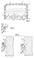
Figur 1- eine schematische Darstellung eines Garantieverschlusses mit den Merkmalen der Erfindung im Querschnitt,
Figur 2- das
Garantieband gemäss Figur 1 in vergrösserter Darstellung und in der Position vor dem Aufsetzen und während des Aufsetzens auf einen Behälterhals, Figur 3- das
Garantieband gemäss Figur 1 und 2 nach dem Aufsetzen auf den Behälterhals, Figur 4- das
Garantieband gemäss Figur 1bis 3 während des Öffnens des Garantieverschlusses, Figur 5- eine weiter vergrösserte Darstellung eines Garantiebands mit den Merkmalen der Erfindung,
Figur 6- ein Garantieband mit Darstellung eines Sperr-Elements in der ersten Schliessposition und der zweiten Öffnungsposition,
Figur 7- ein Garantieband mit einem abgewandelten Sperr-Element,
Figur 8- ein Garantieband mit einer weiteren Ausführungsform eines Sperr-Elements,
Figur 9- die Draufsicht auf ein Garantieband mit einer Mehrzahl von Sperr-Elementen, und
Figur 10bis 15- abgewandelte Ausführungsformen von Sperr-Elementen.
- Figure 1
- 1 shows a schematic representation of a guarantee closure with the features of the invention in cross section,
- Figure 2
- 1 in an enlarged representation and in the position before being placed on and while being placed on a container neck,
- Figure 3
- the guarantee band according to FIGS. 1 and 2 after being placed on the container neck,
- Figure 4
- the guarantee tape according to FIGS. 1 to 3 during the opening of the guarantee closure,
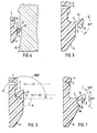
- Figure 5
- 3 shows a further enlarged representation of a guarantee tape with the features of the invention,
- Figure 6
- a guarantee tape showing a locking element in the first closing position and the second opening position,
- Figure 7
- a guarantee band with a modified locking element,
- Figure 8
- a guarantee tape with a further embodiment of a locking element,
- Figure 9
- the top view of a guarantee tape with a plurality of locking elements, and
- Figure 10 to 15
- modified embodiments of locking elements.
Gemäss Figur 1 weist ein Garantieverschluss 1 eine Verschlusskappe 2 auf, welche aus einem Kappenboden 3 und einen zylindrischen Kappenmantel 4 besteht. An der Verschlusskappe 2 ist mittels einer Vielzahl von Sollbruch-Stegen 5 ein Garantieband 6 befestigt.According to FIG. 1, a
Wie besonders gut aus Figur 2 bis 6 ersichtlich wird, ist am Garantieband 6 mittels als Gelenk-Element 7 wirkenden Materialbrücken eine Anzahl von Sperr-Elementen 8 angeordnet.As can be seen particularly well from FIGS. 2 to 6, a number of locking
Die Verschlusskappe 2 ist zusammen mit dem Garantieband 6 und den Sperr-Elementen 8 einstückig in bekannter Weise im Kunststoff-Spritzgussverfahren hergestellt. Selbstverständlich könnte der Garantieverschluss auch im Compression-Molding-Verfahren oder auf andere geeignete Weise hergestellt werden. Auch wäre es denkbar, das Garantieband 6 und die Verschlusskappe 2 getrennt herzustellen und in einem separaten Arbeitsgang miteinander formschlüssig oder auf andere Weise zu verbinden, ohne dass dadurch der Rahmen der Erfindung verlassen würde. Derart separat hergestellte Garantiebänder sind z.B. aus dem US-Patent 4,578,857 bekannt.The
Vor dem Aufschrauben auf einen Behälterhals 9 befinden sich die Sperr-Elemente 8 in der Position N gemäss Figur 1 und oberer Darstellung in Figur 2. Sobald die Verschlusskappe während des Aufschraub-Vorgangs relativ zum Behälterhals nach unten verlagert wird, gelangt das Sperr-Element 8 mit Gewindeabschnitten 10 sowie mit einem umlaufenden, ringförmigen Vorsprung 11 in Eingriff. Die Sperr-Elemente 8 werden dadurch um das Gelenk-Element 7 als Drehpunkt aufwärts und radial auswärts verschwenkt, so dass sich der freie Innendurchmesser des Garantiebands 6 vergrössert und das Garantieband 6 über den Vorsprung 11 in die in Figur 3 dargestellte Position gelangen kann, ohne dass die Sollbruch-Stege 5 dabei beschädigt würden. In der Zwischenstellung N sind die Sperr-Elemente 8 radial nach innen gerichtet, wobei es in dieser Position nicht wesentlich ist, ob sie zusätzlich leicht aufwärts oder leicht abwärts zeigen, da durch die Elastizität des Gelenk-Elements 7 ein Verschwenken in die erste Schliessposition I in jedem Fall möglich ist. In der Schliessposition I bestimmen die Stütz-Oberflächen 12 der Sperr-Elemente 8 den vergrösserten ersten InnendurchmesserD1 (Fig. 6).Before screwing onto a
Nach dem vollständigen Aufschrauben des Garantieverschlusses 1 auf den Behälterhals 9 befinden sich die Sperr-Elemente 8 unterhalb des Vorsprungs 11 und dessen Sperrfläche 13, die der Rückhalte-Öberfläche 14 der Sperr-Elemente 8 zugewandt ist.After the
Figur 4 und 6 zeigen, wie beim Öffnen des Garantieverschlusses die Rückhalte-Oberfläche 14 mit der Sperrfläche 13 in Eingriff kommt, wobei die Rückhalte-Elemente 8 radial einwärts und abwärts in die zweite Öffnungsposition II verschwenkt werden und dabei den zweiten verkleinerten Innendurchmesser D2 bestimmen. Die Sperr-Elemente 8 vergrössern dabei ihren Eingriff mit der Sperrfläche 13, so dass das Garantieband 6 nicht über den Vorsprung 11 gezogen werden kann. Beim Öffnen des Garantieverschlusses reissen deshalb die Sollbruch-Stege 5.FIGS. 4 and 6 show how the retaining
Wie in Figur 5 angedeutet ist, schliessen die Rückhalte-Oberfläche 14 und die Stütz-Oberfläche 12 der Sperr-Elemente 8, von den Gelenk-Elementen 7 her gesehen, einen Winkel von etwa 80° ein. Diese Konfiguration sichert besonders gute Stabilität der Sperr-Elemente 8 und ermöglicht andererseits eine für die Öffnungs- und Schliessfunktion vorteilhafte Verschwenkung der Sperr-Elemente um einen Winkel von etwa 160°, wie in Figur 6 dargestellt.As indicated in FIG. 5, the
Figur 7 zeigt ein abgewandeltes Ausführungsbeispiel, bei welchem die Sperr-Elemente einen etwa V-förmigen Querschnitt aufweisen. Eine solche Querschnittsform ermöglicht besonders einfaches und schnelles Entformen des Garantieverschlusses aus einem axial ausstossenden Spritzgusswerkzeug.Figure 7 shows a modified embodiment in which the locking elements have an approximately V-shaped cross section. Such a cross-sectional shape enables particularly easy and quick demolding of the guarantee closure from an axially ejecting injection molding tool.
Um Stabilität und Abstützfunktion dieser Sperr-Elemente 8 zusätzlich zu sichern, ist an der Innenwand des Garantiebands 6 ein Stütz-Vorsprung 6a vorgesehen, an welchem sich die Stütz-Oberfläche 12 abstützen kann. Beim Ausführungsbeispiel gemäss Figur 7 schliesst die Stütz-Oberfläche 12 mit der Rückhalte-Oberfläche 14 einen Winkel von etwa 60° ein. Aufgrund der Anordnung des Gelenk-Elements 7 ist eine Verschwenkung des Sperr-Elements 8 aus der ersten Schliessposition I in die zweite Öffnungsposition II um etwa 180° möglich.In order to additionally ensure the stability and support function of these locking
Figur 8 zeigt ein abgewandeltes Ausführungsbeispiel, bei welchem die Stütz-Oberfläche 12 der Sperr-Elemente 8 als nockenartiger Vorsprung ausgebildet ist, der in einer entsprechenden Vertiefung 6b des Garantiebands 6 abstützbar ist. Das in Figur 8 gezeigte Garantieband 6 ist mit dem Kappenmantel 4 nicht durch individuelle Materialstege 5 sondern durch eine sehr dünne, durchgehende Materialhaut 5b (über 360°) verbunden.Figure 8 shows a modified embodiment in which the
Figur 9 zeigt eine Draufsicht auf das Garantieband (von unten). Daraus ist ersichtlich, dass die Gelenk-Elemente 7 zur Befestigung der Sperr-Elemente 8 am Garantieband 6 jeweils über die gesamte Länge der Sperr-Elemente 8 verlaufen. Sowohl die Gelenk-Elemente 7 als auch die Sperr-Elemente 8 sind als Kreissegmente geformt und verlaufen koaxial zum Garantieband 6.Figure 9 shows a top view of the guarantee tape (from below). It can be seen from this that the
Figur 10 zeigt dagegen ein Ausführungsbeispiel, bei welchem die Sperr-Elemente 8 jeweils beidseitig mit einem Gelenk-Element 7a, 7b mit dem Garantieband 6 verbunden sind. Diese Ausbildung erlaubt besonders leichtes Verschwenken der Sperr-Elemente 8 beim Aufbringen auf einen Behälterhals.FIG. 10, on the other hand, shows an embodiment in which the
Ausserdem sind die Sperr-Elemente 8 beim Ausführungsbeispiel gemäss Figur 10 geradlinig und nicht als Kreissegmente ausgebildet.In addition, the blocking
Das Ausführungsbeispiel gemäss Figur 11 zeigt die schematische Darstellung eines Sperr-Elements 8, das mittels eines mittig angeordneten, stegartig ausgebildeten Gelenk-Elements 7c mit dem Garantieband 6 verbunden ist.The exemplary embodiment according to FIG. 11 shows the schematic representation of a
Beim Ausführungsbeispiel gemäss Figur 12 ist eine Vielzahl von relativ schmalen Sperr-Elementen 8 vorgesehen, wobei zusätzlich zu den in Figur 1 bis 8 dargestellten Sollbruch-Stellen 5 zwischen dem Garantieband 6 und dem Kappenmantel 4 auch noch Sollbruch-Stellen 5a angebracht sind, die ein radiales Aufreissen des Garantiebands 6 ermöglichen.In the exemplary embodiment according to FIG. 12, a multiplicity of relatively
Beim Ausführungsbeispiel gemäss Figur 13 ist am Garantieband 6 ein Vorsprung 6c vorgesehen, welcher mittels Gelenk-Element 7 das zugeordnete Sperr-Element 8 trägt. Diese Anordnung erlaubt einerseits besonders dünne Ausbildung des Garantiebands 6 und vergrössert andererseits den Verschwenkungswinkel der Sperr-Elemente 8 aus der ersten Verschliessposition I in die zweite Öffnungsposition II (Figur 6).In the exemplary embodiment according to FIG. 13, a
Das Ausführungsbeispiel gemäss Figur 14 zeigt eine geänderte Version des Sperr-Elements 8 von Figur 8. Die Stütz-Oberfläche 12b ist hakenförmig ausgeprägt sodass sie in der entsprechenden Vertiefung 6c einrasten kann. Wenn das Sperr-Element 8 durch Drehen des Garantieverschlusses 1 oder eine andere Manipulation nach unten gebogen wird, fixiert sich das Sperr-Element in seiner unteren Position. Dies erhöht die Sicherheit gegen Manipulation.The exemplary embodiment according to FIG. 14 shows a modified version of the
Das Ausführungsbeispiel gemäss Figur 15 zeigt eine geänderte Version des Garantiebands 6. Das Garantieband 6 weist ein äusseres Band 6d auf, das von der dünnen, durchgehenden Soll-Bruchstelle 5b nach unten verläuft. Im weiteren hat das Garantieband 6 ein inneres Band 6e, das mit dem Äusseren entlang Linie 15 verbunden ist und radial einwärts, schräg nach oben gerichtet ist. Auf der Innenseite des inneren Bandes 6e sind Sperr-Elemente angebracht, wie sie in den Ausführungsbeispielen gemäss Figur 1-14 gezeigt wurden. Bei der Montage dieser Verschlusskappen auf einen Behälter kann sich das innere Band 6e nach aussen biegen und die Sperr-Elemente 8 werden nach oben und aussen verschwenkt. Dies bestimmt den grösseren Durchmesser D1. Beim Öffnen des Garantieverschlusses 1 werden die Sperr-Elemente 8 einwärts nach unten verschwenkt, wobei sich das innere Band 6e nach innen biegen kann und so den durch die Innenfläche der Sperr-Elemente 8 definierten freien Innendurchmesser weiter reduziert.The exemplary embodiment according to FIG. 15 shows a modified version of the
Die gegebenen Beispiele sollen nicht als Einschränkung der Erfindung gewertet werden, da diese weiteren Modifikationen und Variationen zuzöglich ist. Die Erfindung ist vor allem durch die folgenden Patentansprüche und deren verschiedene Kombinationsmöglichkeiten definiert.The examples given should not be interpreted as a limitation of the invention, since these further modifications and variations are possible. The invention is primarily defined by the following claims and their various possible combinations.
Claims (13)
- A guarantee closure cap of plastics material for a container, on the neck (9) of which there is provided at least one radially outwardly projecting locking surface (13), comprising a cap end portion (3) and a cylindrical cap wall portion (4) and a tear-off guarantee strip (6) arranged at the lower edge of the cap wall portion (4) and at least one locking element (8) which is connected to the inside surface of the guarantee strip (6) pivotably by a hinge element (7) and which is in engagement with the locking surface (13) when the closure cap is fitted, characterised in that the locking elements (8) have on the one hand an upper retaining surface (14) which in a first position I extends upwardly and radially outwardly from the hinge elements, in which case the locking elements (8) define an enlarged inside diameter D1, and on the other hand a lower support surface (12) which in a second position II bears against the inside surface of the guarantee strip beneath the hinge element, in which case the locking elements (8) define a smaller inside diameter D2.
- A guarantee closure cap according to claim 1 characterised in that before the closure cap is fitted the locking elements (8) project radially inwardly in an intermediate position (N) between their upper position (I) and their lower position (II).
- A guarantee closure cap according to claim 1 or claim 2 characterised in that the locking elements (8) are pivotable between the first position and the second position through an angle of at least 100°.
- A guarantee closure cap according to claim 3 characterised in that the locking elements (8) are pivotable between the first and the second positions in an angle of at least 140°.
- A guarantee closure cap according to claim 4 characterised in that the locking elements (8) are pivotable between the first and the second positions through an angle of about 160° to 180°.
- A guarantee closure cap according to one of claims 1 to 5 characterised in that the retaining surface (14) and the support surface (12) include an angle of at least 60°.
- A guarantee closure cap according to claim 6 characterised in that the retaining surface (14) and the support surface (12) include an angle of about 70° to 100°.
- A guarantee closure cap according to one of claims 1 to 7 characterised in that the hinge element (7) has at least one flexible material bridge portion connecting the guarantee strip (6) to a locking element (8).
- A guarantee closure cap according to one of claims 1 to 8 characterised in that as viewed in plan the locking elements (8) are in the shape of a segment of a circle, the circle of which extends coaxially with the guarantee strip (6).
- A guarantee closure cap according to one of claims 1 to 8 characterised in that as viewed in plan the locking elements (8) extend approximately rectilinearly.
- A guarantee closure cap according to one of claims 1 to 10 characterised in that the guarantee strip has both an outer strip (6d) and an inner strip (6e) which is directed inwardly upwardly from the lower edge of the outer strip (6d) and that the locking elements (8) are disposed on the inner strip (6e).
- A guarantee closure cap according to one of claims 1 to 11 characterised in that the support surface (12) of the locking elements (8) is in the form of a dog-like projection which can be supported in a corresponding recess (6b) in the guarantee strip.
- A guarantee closure cap according to claim 12 characterised in that the dog-like projection of the support surface (12) is shaped in a hook-like configuration so that it can engage into a corresponding recess (6c).
Applications Claiming Priority (2)
| Application Number | Priority Date | Filing Date | Title |
|---|---|---|---|
| US961134 | 1992-10-14 | ||
| US07/961,134 US5356019A (en) | 1992-10-14 | 1992-10-14 | Tamper indicating plastic closure |
Publications (2)
| Publication Number | Publication Date |
|---|---|
| EP0593396A1 EP0593396A1 (en) | 1994-04-20 |
| EP0593396B1 true EP0593396B1 (en) | 1996-01-31 |
Family
ID=25504110
Family Applications (1)
| Application Number | Title | Priority Date | Filing Date |
|---|---|---|---|
| EP93810706A Expired - Lifetime EP0593396B1 (en) | 1992-10-14 | 1993-10-06 | Tamper proof plastic closure |
Country Status (13)
| Country | Link |
|---|---|
| US (1) | US5356019A (en) |
| EP (1) | EP0593396B1 (en) |
| JP (1) | JPH06199356A (en) |
| CN (1) | CN1086782A (en) |
| AU (1) | AU665272B2 (en) |
| BR (1) | BR9304174A (en) |
| CA (1) | CA2107805A1 (en) |
| DE (1) | DE59301547D1 (en) |
| ES (1) | ES2082620T3 (en) |
| NZ (1) | NZ248925A (en) |
| PL (1) | PL300677A1 (en) |
| TR (1) | TR27602A (en) |
| ZA (1) | ZA937591B (en) |
Families Citing this family (37)
| Publication number | Priority date | Publication date | Assignee | Title |
|---|---|---|---|---|
| US5937726A (en) * | 1991-06-29 | 1999-08-17 | Alcoa Deutschland Gmbh | Method for cutting vertical incision in container cap |
| US5450973A (en) * | 1994-09-22 | 1995-09-19 | Eagle Engraving And Mold Corp. | Tamper-evident closure apparatus |
| US5588562A (en) * | 1994-10-31 | 1996-12-31 | Sander; Dieter | Tamper evident resealable plastic closure |
| US5813553A (en) * | 1995-06-07 | 1998-09-29 | Kerr Group, Inc. | Snap-band tamper evident |
| DE69626419T2 (en) * | 1995-06-14 | 2003-12-24 | Bruno Zumbuhl | SCREW CAP FOR PRESSURE VESSEL |
| JP2933308B2 (en) * | 1996-12-03 | 1999-08-09 | 聖次 西原 | Pill fur proof cap made of synthetic resin |
| US5979682A (en) * | 1997-04-14 | 1999-11-09 | Zumbuhl; Bruno | Tab construction for closures having tamper evident rings |
| IT1293269B1 (en) * | 1997-07-25 | 1999-02-16 | Sacmi | SCREW CAPS IN PLASTIC MATERIAL WITH GUARANTEE RING. |
| US6085921A (en) * | 1998-02-26 | 2000-07-11 | Crown Cork & Seal Technologies Corporation | Tamper evident band with undercut |
| IT1300020B1 (en) * | 1998-05-08 | 2000-04-04 | Sacmi | SCREW CAP IN PLASTIC MATERIAL WITH GUARANTEE RING. |
| US6253939B1 (en) | 1999-01-04 | 2001-07-03 | Crown Cork & Seal Technologies Corporation | Tamper-evident closure having improved drainage |
| US6568548B1 (en) * | 2000-06-19 | 2003-05-27 | Rexam Medical Packaging Inc. | Closure with tamper-indicating band |
| EP1397296B8 (en) * | 2001-06-18 | 2005-11-23 | Bericap Holding GmbH | Screw cap comprising a tamper-evident band |
| EP1417135B1 (en) * | 2001-08-13 | 2005-01-05 | CROWN Packaging Technology, Inc. | A closure cap |
| AU2002360031A1 (en) * | 2001-12-28 | 2003-07-24 | Toyo Seikan Kaisha, Ltd. | Container sealing structure, container with the sealing structure, and method of manufacturing the sealing structure |
| US7637384B2 (en) * | 2002-08-09 | 2009-12-29 | Crown Packaging Technology, Inc. | Tamper evident closure with locking band and container therefor |
| US20040045925A1 (en) * | 2002-09-11 | 2004-03-11 | Seidita Thomas M. | Tamper evident closure with locking band |
| US7222741B2 (en) * | 2003-01-24 | 2007-05-29 | J.C. Products, Inc. | Tamper evident cap |
| US20050167389A1 (en) * | 2004-02-04 | 2005-08-04 | Price Michael L. | Closure with improved resistance to deformation during opening |
| US20060151423A1 (en) * | 2004-03-11 | 2006-07-13 | Seidita Thomas M | Closure having tapered sealing plug |
| DE102004014758A1 (en) * | 2004-03-23 | 2005-10-06 | Bericap Gmbh & Co. Kg | Closure cap with guarantee tape has cap jacket with internal aperture to retain thick edge of flexible tape |
| ITMO20040201A1 (en) * | 2004-07-30 | 2004-10-30 | Sacmi | CAPSULE FOR CONTAINERS. |
| US20060163192A1 (en) * | 2005-01-14 | 2006-07-27 | Price Michael L | Linerless plastic closure |
| FR2890943B1 (en) * | 2005-09-21 | 2010-04-16 | Tetra Laval Holdings & Finance | DEVICE FOR CLOSING A CONTAINER COLLAR, CONTAINER EQUIPPED WITH SUCH A DEVICE AND METHOD FOR MANUFACTURING SUCH A DEVICE |
| US8353413B2 (en) * | 2007-01-05 | 2013-01-15 | Phoenix Closures, Inc. | Tamper-evident closure and container combination |
| US20080173611A1 (en) * | 2007-01-18 | 2008-07-24 | Silgan Holdings Inc. | Tamper evident band with hook |
| CN101678692B (en) * | 2007-05-09 | 2012-07-11 | 阿克泰加Ds有限公司 | Use of spherical metal particles as laser marking additives for sealing, closure or coating materials or paints comprising polymer, and also laser-markable sealing, closure or coating material or lase |
| US8276777B2 (en) * | 2008-10-03 | 2012-10-02 | Chuck Shieh | Closure with tamper evident strip for container |
| JP6128831B2 (en) * | 2012-12-21 | 2017-05-17 | 日本クロージャー株式会社 | Plastic container lid |
| BR302014001174S1 (en) | 2013-09-18 | 2015-05-12 | Bericap | Ornamental configuration applied on lid |
| FR3015442B1 (en) | 2013-12-24 | 2016-02-05 | Bericap | ARTICULATED CLAMPING DEVICE WITH FIRST OPENING INDICATOR |
| USD833278S1 (en) | 2014-09-03 | 2018-11-13 | Bericap | Closure for a container |
| IT201600080146A1 (en) * | 2016-07-29 | 2018-01-29 | Guala Pack Spa | CLOSURE WITH A GUARANTEE SEAL |
| JP7037915B2 (en) * | 2017-11-06 | 2022-03-17 | 日本山村硝子株式会社 | Synthetic resin caps and containers |
| US10899505B2 (en) * | 2019-01-10 | 2021-01-26 | Silgan White Cap LLC | Band-receiving closure with recess |
| US11059633B2 (en) | 2019-10-31 | 2021-07-13 | Cheer Pack North America | Flip-top closure for container |
| EP4186810A3 (en) * | 2023-03-28 | 2023-10-18 | PCHB bvba | Lid-spout assembly, lid-assembly, and package for a pourable product |
Family Cites Families (15)
| Publication number | Priority date | Publication date | Assignee | Title |
|---|---|---|---|---|
| JPS58139462U (en) * | 1982-03-15 | 1983-09-20 | 日本クラウンコルク株式会社 | Synthetic resin container lid |
| US4635808A (en) * | 1982-12-14 | 1987-01-13 | Maxcap, Inc. | Plastic cap |
| EP0146237A1 (en) * | 1983-10-27 | 1985-06-26 | Continental White Cap, Inc. | Closure with tamper indicating band |
| US4694971A (en) * | 1986-12-04 | 1987-09-22 | Thad Elsmo | Tamperproof package |
| CH671205A5 (en) * | 1987-02-26 | 1989-08-15 | Crown Cork Ag | |
| US4726482A (en) * | 1987-03-27 | 1988-02-23 | Owens-Illinois Closure Inc. | Tamper indicating package and molded plastic closure therefor |
| US4813561A (en) * | 1988-02-29 | 1989-03-21 | Anchor Hocking Corporation | Composite retortable closure |
| CA2008769C (en) * | 1989-01-30 | 2002-03-19 | Stephen W. Mcbride | Tamper-indicating plastic closure |
| US4938370B1 (en) * | 1989-04-26 | 2000-10-17 | Hc Ind | Tamper-indicating plastic closure |
| US4978017A (en) * | 1989-04-26 | 1990-12-18 | H-C Industries, Inc. | Tamper-indicating plastic closure |
| US5090788A (en) * | 1989-07-27 | 1992-02-25 | Owens-Illinois Closure Inc. | Tamper indicating package |
| US5167335A (en) * | 1991-04-09 | 1992-12-01 | H-C Industries, Inc. | Tamper-indicating plastic closure |
| US5205426A (en) * | 1991-04-09 | 1993-04-27 | H-C Industries, Inc. | Tamper-indicating plastic closure |
| US5107998A (en) * | 1991-06-14 | 1992-04-28 | Bruno Zumbuhl | Tamper proof ring for threaded closures |
| DE4201997C1 (en) * | 1992-01-25 | 1992-12-10 | Stella Kunststofftechnik Gmbh, 6228 Eltville, De |
-
1992
- 1992-10-14 US US07/961,134 patent/US5356019A/en not_active Expired - Fee Related
-
1993
- 1993-09-15 AU AU47351/93A patent/AU665272B2/en not_active Ceased
- 1993-10-06 ES ES93810706T patent/ES2082620T3/en not_active Expired - Lifetime
- 1993-10-06 CA CA002107805A patent/CA2107805A1/en not_active Abandoned
- 1993-10-06 DE DE59301547T patent/DE59301547D1/en not_active Expired - Fee Related
- 1993-10-06 EP EP93810706A patent/EP0593396B1/en not_active Expired - Lifetime
- 1993-10-07 BR BR9304174A patent/BR9304174A/en not_active Application Discontinuation
- 1993-10-12 PL PL93300677A patent/PL300677A1/en unknown
- 1993-10-12 NZ NZ248925A patent/NZ248925A/en unknown
- 1993-10-13 ZA ZA937591A patent/ZA937591B/en unknown
- 1993-10-13 CN CN93119196A patent/CN1086782A/en not_active Withdrawn
- 1993-10-14 TR TR00946/93A patent/TR27602A/en unknown
- 1993-10-14 JP JP5256641A patent/JPH06199356A/en active Pending
Also Published As
| Publication number | Publication date |
|---|---|
| US5356019A (en) | 1994-10-18 |
| BR9304174A (en) | 1994-04-19 |
| PL300677A1 (en) | 1994-04-18 |
| TR27602A (en) | 1995-06-13 |
| ES2082620T3 (en) | 1996-03-16 |
| DE59301547D1 (en) | 1996-03-14 |
| AU665272B2 (en) | 1995-12-21 |
| ZA937591B (en) | 1994-05-03 |
| NZ248925A (en) | 1995-07-26 |
| CA2107805A1 (en) | 1994-04-15 |
| JPH06199356A (en) | 1994-07-19 |
| CN1086782A (en) | 1994-05-18 |
| EP0593396A1 (en) | 1994-04-20 |
| AU4735193A (en) | 1994-04-28 |
Similar Documents
| Publication | Publication Date | Title |
|---|---|---|
| EP0593396B1 (en) | Tamper proof plastic closure | |
| DE69309951T2 (en) | CONTAINER LOCK WITH ORIGINALITY TAPE | |
| DE69413152T2 (en) | Anti-theft lock made of plastic | |
| DE69323423T2 (en) | SCREWLOCK SAFE AGAINST MANIPULATION | |
| DE69017033T2 (en) | ORIGINAL CLOSURE WITH A BROKEN HOLDER. | |
| EP0810952B1 (en) | Closure cap with retaining strip | |
| DE69322514T3 (en) | GUARANTEE CLOSURE | |
| DE69504065T2 (en) | ORIGINALITY HINGE CLOSURE | |
| DE69702672T2 (en) | CAP FOR CLOSING A TANK OPENING | |
| EP0553685B1 (en) | Container closure having a tamper indicating ring | |
| EP0049876A1 (en) | Tamperproof screw closure | |
| EP0254673A1 (en) | Container closure provided with a tamper indicating band | |
| DE69626419T2 (en) | SCREW CAP FOR PRESSURE VESSEL | |
| EP0371920B1 (en) | Screw cap with a tamper-evident band | |
| EP0281514A1 (en) | Closure cap with a warranty strap | |
| DE19617350A1 (en) | Cap lock | |
| EP0451102B1 (en) | Plastic closure | |
| DE19700308A1 (en) | Plastic screw cap for bottles | |
| DE2638351C3 (en) | Guarantee cap for bottles | |
| DE2233305A1 (en) | SCREW CAP WITH ORIGINAL LOCKING RING | |
| EP0589254B1 (en) | Tamper-proof closure | |
| EP0387302B1 (en) | Tamper-proof closure | |
| DE3224002A1 (en) | Tamper-proof closure | |
| DE19712364A1 (en) | Bottle snap closure cap | |
| WO2006032329A1 (en) | Dispensing closure for liquid containers, especially drinks containers |
Legal Events
| Date | Code | Title | Description |
|---|---|---|---|
| PUAI | Public reference made under article 153(3) epc to a published international application that has entered the european phase |
Free format text: ORIGINAL CODE: 0009012 |
|
| AK | Designated contracting states |
Kind code of ref document: A1 Designated state(s): BE CH DE ES FR GB IT LI |
|
| 17P | Request for examination filed |
Effective date: 19940606 |
|
| 17Q | First examination report despatched |
Effective date: 19940916 |
|
| GRAA | (expected) grant |
Free format text: ORIGINAL CODE: 0009210 |
|
| AK | Designated contracting states |
Kind code of ref document: B1 Designated state(s): BE CH DE ES FR GB IT LI |
|
| REF | Corresponds to: |
Ref document number: 59301547 Country of ref document: DE Date of ref document: 19960314 |
|
| REG | Reference to a national code |
Ref country code: ES Ref legal event code: FG2A Ref document number: 2082620 Country of ref document: ES Kind code of ref document: T3 |
|
| ET | Fr: translation filed | ||
| REG | Reference to a national code |
Ref country code: CH Ref legal event code: NV Representative=s name: HEPP, WENGER & RYFFEL AG |
|
| ITF | It: translation for a ep patent filed | ||
| GBT | Gb: translation of ep patent filed (gb section 77(6)(a)/1977) |
Effective date: 19960418 |
|
| PLBE | No opposition filed within time limit |
Free format text: ORIGINAL CODE: 0009261 |
|
| STAA | Information on the status of an ep patent application or granted ep patent |
Free format text: STATUS: NO OPPOSITION FILED WITHIN TIME LIMIT |
|
| 26N | No opposition filed | ||
| PGFP | Annual fee paid to national office [announced via postgrant information from national office to epo] |
Ref country code: BE Payment date: 19991004 Year of fee payment: 7 |
|
| PGFP | Annual fee paid to national office [announced via postgrant information from national office to epo] |
Ref country code: FR Payment date: 20000911 Year of fee payment: 8 |
|
| PGFP | Annual fee paid to national office [announced via postgrant information from national office to epo] |
Ref country code: GB Payment date: 20000919 Year of fee payment: 8 |
|
| PGFP | Annual fee paid to national office [announced via postgrant information from national office to epo] |
Ref country code: CH Payment date: 20000921 Year of fee payment: 8 |
|
| PGFP | Annual fee paid to national office [announced via postgrant information from national office to epo] |
Ref country code: DE Payment date: 20000925 Year of fee payment: 8 |
|
| PGFP | Annual fee paid to national office [announced via postgrant information from national office to epo] |
Ref country code: ES Payment date: 20001009 Year of fee payment: 8 |
|
| PG25 | Lapsed in a contracting state [announced via postgrant information from national office to epo] |
Ref country code: BE Free format text: LAPSE BECAUSE OF NON-PAYMENT OF DUE FEES Effective date: 20001031 |
|
| BERE | Be: lapsed |
Owner name: CROWN CORK & SEAL CY INC. Effective date: 20001031 |
|
| PG25 | Lapsed in a contracting state [announced via postgrant information from national office to epo] |
Ref country code: GB Free format text: LAPSE BECAUSE OF NON-PAYMENT OF DUE FEES Effective date: 20011006 |
|
| PG25 | Lapsed in a contracting state [announced via postgrant information from national office to epo] |
Ref country code: ES Free format text: LAPSE BECAUSE OF NON-PAYMENT OF DUE FEES Effective date: 20011007 |
|
| PG25 | Lapsed in a contracting state [announced via postgrant information from national office to epo] |
Ref country code: LI Free format text: LAPSE BECAUSE OF NON-PAYMENT OF DUE FEES Effective date: 20011031 Ref country code: CH Free format text: LAPSE BECAUSE OF NON-PAYMENT OF DUE FEES Effective date: 20011031 |
|
| REG | Reference to a national code |
Ref country code: GB Ref legal event code: IF02 |
|
| GBPC | Gb: european patent ceased through non-payment of renewal fee |
Effective date: 20011006 |
|
| REG | Reference to a national code |
Ref country code: CH Ref legal event code: PL |
|
| PG25 | Lapsed in a contracting state [announced via postgrant information from national office to epo] |
Ref country code: FR Free format text: LAPSE BECAUSE OF NON-PAYMENT OF DUE FEES Effective date: 20020628 |
|
| PG25 | Lapsed in a contracting state [announced via postgrant information from national office to epo] |
Ref country code: DE Free format text: LAPSE BECAUSE OF NON-PAYMENT OF DUE FEES Effective date: 20020702 |
|
| REG | Reference to a national code |
Ref country code: FR Ref legal event code: ST |
|
| REG | Reference to a national code |
Ref country code: ES Ref legal event code: FD2A Effective date: 20021113 |
|
| PG25 | Lapsed in a contracting state [announced via postgrant information from national office to epo] |
Ref country code: IT Free format text: LAPSE BECAUSE OF NON-PAYMENT OF DUE FEES;WARNING: LAPSES OF ITALIAN PATENTS WITH EFFECTIVE DATE BEFORE 2007 MAY HAVE OCCURRED AT ANY TIME BEFORE 2007. THE CORRECT EFFECTIVE DATE MAY BE DIFFERENT FROM THE ONE RECORDED. Effective date: 20051006 |