US5167335A - Tamper-indicating plastic closure - Google Patents
Tamper-indicating plastic closure Download PDFInfo
- Publication number
- US5167335A US5167335A US07/682,635 US68263591A US5167335A US 5167335 A US5167335 A US 5167335A US 68263591 A US68263591 A US 68263591A US 5167335 A US5167335 A US 5167335A
- Authority
- US
- United States
- Prior art keywords
- tab
- annular
- closure
- tamper
- pilfer band
- Prior art date
- Legal status (The legal status is an assumption and is not a legal conclusion. Google has not performed a legal analysis and makes no representation as to the accuracy of the status listed.)
- Expired - Lifetime
Links
Images

Classifications
-
- B—PERFORMING OPERATIONS; TRANSPORTING
- B65—CONVEYING; PACKING; STORING; HANDLING THIN OR FILAMENTARY MATERIAL
- B65D—CONTAINERS FOR STORAGE OR TRANSPORT OF ARTICLES OR MATERIALS, e.g. BAGS, BARRELS, BOTTLES, BOXES, CANS, CARTONS, CRATES, DRUMS, JARS, TANKS, HOPPERS, FORWARDING CONTAINERS; ACCESSORIES, CLOSURES, OR FITTINGS THEREFOR; PACKAGING ELEMENTS; PACKAGES
- B65D41/00—Caps, e.g. crown caps or crown seals, i.e. members having parts arranged for engagement with the external periphery of a neck or wall defining a pouring opening or discharge aperture; Protective cap-like covers for closure members, e.g. decorative covers of metal foil or paper
- B65D41/32—Caps or cap-like covers with lines of weakness, tearing-strips, tags, or like opening or removal devices, e.g. to facilitate formation of pouring openings
- B65D41/34—Threaded or like caps or cap-like covers provided with tamper elements formed in, or attached to, the closure skirt
- B65D41/3423—Threaded or like caps or cap-like covers provided with tamper elements formed in, or attached to, the closure skirt with flexible tabs, or elements rotated from a non-engaging to an engaging position, formed on the tamper element or in the closure skirt
- B65D41/3428—Threaded or like caps or cap-like covers provided with tamper elements formed in, or attached to, the closure skirt with flexible tabs, or elements rotated from a non-engaging to an engaging position, formed on the tamper element or in the closure skirt the tamper element being integrally connected to the closure by means of bridges
Definitions
- the present invention relates generally to tamper-indicating closures for containers, and more particularly to a tamper-evident plastic closure including a pilfer band configured for enhanced flexibility having container-engaging projections to facilitate application of the closure to a container with high-speed application equipment.
- Tamper-indicating or tamper-evident packaging for food products and beverages assures consumers that products are fresh and unadulterated when purchased.
- U.S. Pat. No. 4,938,370, to McBride illustrates a tamper-indicating plastic closure construction for use in connection with a bottle or like container having a threaded neck.
- the closure disclosed in this patent is particularly desirable in that two different modes of tamper-indication are provided, thus enhancing its tamper-resistance.
- the closure of this patent includes an annular pilfer band which is at least partially detachably joined to the bottom of a cylindrical skirt portion of an upper closure cap.
- the pilfer band includes a plurality of circumferentially spaced, relatively flexible tab elements which extend inwardly of the pilfer band for coaction with an annular locking ring on an associated container.
- the flexible tabs are urged upwardly.
- the tabs assume a more inwardly extending disposition, for coaction with the container locking ring so that the pilfer band is detached from the skirt portion during closure removal.
- the pilfer band includes an annular interference bead positioned generally beneath the flexible tabs. In the event that the pilfer band does not initially detach from the closure skirt portion, by virtue of the tabs interacting with the container in their initial upwardly and inwardly extending disposition, the tabs can further function to cooperate with the interference bead.
- the upward flexing movement of the flexible tabs during closure application creates stresses on the closure, including stress on the frangible connection which detachably connects the pilfer band to the closure skirt portion.
- the stresses exerted on the frangible connection can be relatively high. This poses somewhat of a dilemma, in that the frangible connection must be configured to consistently and easily fracture and break attendant to closure removal, while at the same time be sufficiently strong to resist premature breakage during high-speed application.
- the present invention contemplates an improved construction for a tamper-indicating closure of the above type, which construction facilitates high-speed closure application without compromise of the reliable performance of the closure.
- the tamper-indicating plastic closure of the present invention facilitates high-speed closure application by reducing the stresses to which the closure is subjected during application. This is achieved by configuring the flexible tab elements of the closure pilfer band for enhanced flexibility, while at the same time assuring operability in the two different modes of tamper-indication.
- the flexible tabs are configured for enhanced flexibility by including a base portion of relatively reduced thickness for enhanced flexibility, as well as a locally thickened portion for the desired coaction with an interference bead of the pilfer band.
- the present tamper-indicating plastic closure is configured for use with a container having an annular locking ring.
- the closure comprises a plastic cap including a top wall portion, and an annular depending cylindrical skirt portion.
- a helical thread formation is provided on the inside surface of the skirt portion for coaction with a like thread formation on the exterior finish of the associated container.
- the closure further includes an annular pilfer band at least partially detachably connected to and depending from the skirt portion of the closure.
- the pilfer band includes an annular band portion, and a plurality of circumferentially spaced inwardly extending flexible tabs. Each flexible tab has a free end portion which is engageable with the container locking ring when the flexible tabs extend upwardly and inwardly during removal of the closure from the container.
- the pilfer band further includes an inwardly extending annular interference bead positioned beneath and adjacent to the flexible tabs.
- a second means or mode of tamper-indication is provided by disposition of the flexible tabs in a generally downwardly, inwardly extending orientation, between the container locking ring and the interference bead of the pilfer band.
- the flexible tabs are configured for enhanced flexibility, thereby facilitating high-speed application to containers with relatively reduced stressing of the closure.
- These tabs include a relatively thick central portion, and a base portion having a relatively reduced thickness to enhance the flexibility of the tab.
- each of the relatively thick central portions is positionable between the associated container locking ring and the interference bead of the pilfer band.
- each of the flexible tabs has a generally planar configuration, with the relatively thick central portion comprising a discrete, elongated pad or node on a lower surface of the planar portion of the tab.
- a preferred frangible connection for at least partially detachably connecting the pilfer band to the closure skirt comprises a plurality of circumferentially spaced, frangible ribs or bridges which extend between the inside surfaces of the skirt portion and the annular band portion of the pilfer band.
- the pilfer band is otherwise separated and distinguished from the skirt portion by a circumferentially extending score line which extends at least partially around the closure. The score line extends partially into the frangible ribs, thereby defining a fracturable "residual" portion for each rib.
- each of the flexible tabs configured for enhanced flexibility includes a base portion of relatively reduced thickness.
- each of these flexible tabs also includes a free end portion of relatively reduced thickness, which is preferably of substantially equal thickness to the base portion.
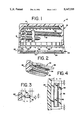
- FIG. 1 is a cross-sectional view of a tamper-indicating plastic closure embodying the principles of the present invention
- FIG. 2 is a relatively enlarged, fragmentary perspective view illustrating a flexible tab of a pilfer band of the closure shown in FIG. 1;
- FIG. 3 is a side elevational view of the flexible tabs shown in FIG. 2;
- FIG. 4 is a bottom plan view of the flexible tabs shown in FIG. 2;
- FIG. 5 is a fragmentary view illustrating the action of the present tamper-indicating closure in a first mode of tamper-indication
- FIG. 6 is a view similar to FIG. 5 illustrating the present closure in a second mode of tamper-indication.
- the plastic closure 10 includes an upper plastic closure cap or shell 12, preferably formed from polypropylene, which includes a circular top wall portion 14, and a depending, annular cylindrical skirt portion 16.
- the skirt portion 16 includes an internal, helical thread formation 18 for mating with a like thread formation on the exterior finish of an associated container.
- the illustrated embodiment of the closure 10 is particularly configured for use with containers for carbonated beverages, and to this end, a plurality of axially extending vent grooves 20 are provided in the skirt portion 16, generally traversing the thread formation 18. Additionally, the closure may include a sealing liner 22 adjacent the top wall portion 14, which is configured for sealing engagement with the associated container.
- the closure includes an annular pilfer band 24 depending from the lower edge of skirt portion 16.
- the pilfer band 24 is at least partially detachably connected to the skirt portion 16, with the pilfer band being configured for cooperative interaction with an locking ring L (FIGS. 5 and 6) of an associated container for at least partially detaching and separating the pilfer band from the closure skirt portion.
- the pilfer band 24 includes an annular band portion 26.
- the desired frangible connection between the pilfer band and the closure skirt portion is preferably provided by a plurality of circumferentially spaced, frangible rib-like bridges 28 which extend between the inside surfaces of the skirt portion 16 and the band portion 26 of the pilfer band.
- the pilfer band is otherwise separated and distinguished from the skirt portion of the closure cap 12 by a circumferential score line 30 which extends through the side wall of the closure construction, and partially into the frangible ribs 28.
- each of the frangible ribs 28 defines an unscored "residual" portion, which residual portions collectively provide a frangible connection between the pilfer band and the closure cap.
- the score line 30 can extend substantially completely about the circumference of the closure. In distinction, for some applications it is desirable to have the pilfer band remain attached to the closure cap, after partial separation of the closure therefrom.
- the band portion 26 of the pilfer band can be configured to break and split in one or more regions, attendant to failure of the frangible bridges 28, with the one or more pieces of the pilfer band thereafter remaining attached to the skirt portion of the closure by one or more areas exhibiting relatively greater strength than the bridges 28.
- the pilfer band 24 of the plastic closure 10 is desirably configured to provide two modes or arrangements for interacting with the locking ring L of the associated container, thus effecting partial or complete separation of the pilfer band from the closure skirt portion by fracture of the bridges 28.
- the pilfer band 24 includes a plurality of circumferentially spaced, inwardly extending flexible tabs 32 which extend integrally inwardly of the band portion 26.
- the pilfer band includes an inwardly extending, annular interference bead 34 positioned generally beneath the flexible tabs 32.
- FIGS. 5 and 6 The two modes of tamper-indication are diagrammatically illustrated in FIGS. 5 and 6.
- the pilfer band 24 is positioned relative to the container locking ring L such that the flexible tabs 32 can assume a generally inwardly extending, upwardly angled disposition.
- the flexible tabs are preferably dimensioned so that they can flex to an out-of-the-way disposition (shown in phantom line in FIG. 5) during application of the closure to the container.
- removal of the closure from the container acts to urge the flexible tabs into interfering engagement with the container locking ring L whereupon the resultant stresses act to break the frangible ribs 28, so that the pilfer band is at least partially separated from the skirt portion 16.
- a second mode of operation is provided as illustrated diagrammatically in FIG. 6.
- the tabs 32 are configured to coact with the annular interference bead 34, of the pilfer band 24. This coaction reduces the effective inside diameter of the pilfer band of the closure, and thereby effects the desired interfering engagement with the container locking ring L.
- FIG. 6 wherein the disposition of flexible tab 32 between the container locking ring and the annular interference bead 34 provides the second arrangement for at least partially detaching the pilfer band 24 from the skirt portion 16 by fracturing bridges 28.
- frangible bridges 28 it is very desirable that any premature failure or fracture of the frangible bridges 28 be avoided during application of the closure 10 to an associated container.
- frangible bridges reliably and consistently fail and fracture attendant to removal of the closure from the container.
- the collective strength of the frangible bridges 28 is carefully controlled by controlling the depth to which the circumferential score 30 is cut through the closure side wall and partially into the frangible bridges. Nevertheless, it has been found that enhanced reliability can be achieved by facilitating application of the closure to a container in a manner which avoids subjecting the frangible bridges to excessive stress.
- each of the flexible tabs 32 are configured in accordance with the present invention for enhanced flexibility.
- each of the flexible tabs has a generally planar configuration, including a planar portion 36.
- at least some of the flexible tabs, and preferably all of them, include a locally thickened or enlarged region defined by a generally elongated pad or node 38.
- the pad or node of each flexible tab is positioned on the generally downwardly facing lower surface of the tab, and thus acts to define a base portion, adjacent the band portion 26, having a relatively reduced thickness to enhance the flexibility of the tab.
- each of the tabs 32 having a pad 38 also includes a free end portion of relatively reduced thickness, compared to the central portion, with the base portion and free end portion of substantially equal thickness.
- the enhanced flexibility afforded by the base portion of reduced thickness facilitates the upward movement of the tabs during application of the closure to a container.
- the region of relatively greater thickness at the pad 38 still assures the desired cooperation with the interference bead 34 in the second mode of tamper-indication.
- the pad 38 of each flexible tab is engageable with the annular interference bead 34 when the tabs extend inwardly and downwardly, and are disposed between the interference bead and the container locking ring L.
- each tab defines a generally flat surface extending between arcuate edge portions.
- Typical dimensions for the flexible tabs 32 are illustrated in FIGS. 3 and 4. These dimensions are intended as illustrative of a current embodiment, but are not intended to limit the invention to these presently preferred dimensional characteristics.
- each flexible tab 32 has a thickness dimension "t" on the order of about 0.005 to 0.020 inches, with the base and free end portions having this thickness dimension.
- the thickness or height "h" of each of the pads 38 is on the order of about 0.005 to 0.020 inches, for a total maximum tab thickness of 0.010 to 0.040 inches.
- each pad 38 is preferably on the order of about 0.040 to 0.060 inches, with the adjacent portions of each tab having radial dimensions "y" and “z” on the order of about 0.005 to 0.015 inches, respectively.
- the pad 38 is generally radially centered on the respective tab.
- each flexible tab 32 is preferably on the order of about 0.200 to 0.400 inches, with the pad 38 of each tab spaced inwardly from each of the side edges of the respective tab by a dimension "a" on the order of about 0.005 to 0.015 inches.
Abstract
Description
Claims (19)
Priority Applications (20)
| Application Number | Priority Date | Filing Date | Title |
|---|---|---|---|
| US07/682,635 US5167335A (en) | 1991-04-09 | 1991-04-09 | Tamper-indicating plastic closure |
| US07/847,544 US5205426A (en) | 1991-04-09 | 1992-03-13 | Tamper-indicating plastic closure |
| NZ24217992A NZ242179A (en) | 1991-04-09 | 1992-03-31 | Tamper-indicating plastics cap has detachable pilfer band with tab pads squeezed between a container locking ring and pilfer band beads |
| AU13960/92A AU649118B2 (en) | 1991-04-09 | 1992-04-01 | Tamper-indicating plastic closure |
| ZA922387A ZA922387B (en) | 1991-04-09 | 1992-04-01 | Tamper-indicating plastic closure |
| IL10147092A IL101470A (en) | 1991-04-09 | 1992-04-02 | Tamper-indicating plastic closure |
| MYPI92000584A MY108613A (en) | 1991-04-09 | 1992-04-04 | Tamper-indicating plastic closure. |
| MA22777A MA22496A1 (en) | 1991-04-09 | 1992-04-07 | PLASTIC PLUG INDICATING ALTERATION |
| EG18092A EG19477A (en) | 1991-04-09 | 1992-04-07 | Tamper - indicating plastic closure |
| BR929201259A BR9201259A (en) | 1991-04-09 | 1992-04-08 | VIOLATION INDICATOR PLASTIC COVER |
| DE69202806T DE69202806T2 (en) | 1991-04-09 | 1992-04-08 | Tamper-evident closure made of plastic. |
| FI921556A FI108939B (en) | 1991-04-09 | 1992-04-08 | Plastic closure for unauthorized use |
| CA002065606A CA2065606A1 (en) | 1991-04-09 | 1992-04-08 | Tamper-indicating plastic closure |
| NO92921391A NO921391L (en) | 1991-04-09 | 1992-04-08 | TUKLE INDICATING PLASTIC LID |
| DK92106060.4T DK0508396T3 (en) | 1991-04-09 | 1992-04-08 | Plastic lid with opening indicator |
| ES92106060T ES2075516T3 (en) | 1991-04-09 | 1992-04-08 | PLASTIC CLOSURE WITH HANDLING INDICATION. |
| EP92106060A EP0508396B1 (en) | 1991-04-09 | 1992-04-08 | Tamper-indicating plastic closure |
| JP11681392A JP3382964B2 (en) | 1991-04-09 | 1992-04-09 | Fraudulent plastic closure |
| TR92/0316A TR25983A (en) | 1991-04-09 | 1992-04-09 | PLASTIC COVER WHICH MIXED MIXED |
| TW081102885A TW202413B (en) | 1991-04-09 | 1992-04-14 |
Applications Claiming Priority (1)
| Application Number | Priority Date | Filing Date | Title |
|---|---|---|---|
| US07/682,635 US5167335A (en) | 1991-04-09 | 1991-04-09 | Tamper-indicating plastic closure |
Related Child Applications (1)
| Application Number | Title | Priority Date | Filing Date |
|---|---|---|---|
| US07/847,544 Continuation-In-Part US5205426A (en) | 1991-04-09 | 1992-03-13 | Tamper-indicating plastic closure |
Publications (1)
| Publication Number | Publication Date |
|---|---|
| US5167335A true US5167335A (en) | 1992-12-01 |
Family
ID=24740523
Family Applications (1)
| Application Number | Title | Priority Date | Filing Date |
|---|---|---|---|
| US07/682,635 Expired - Lifetime US5167335A (en) | 1991-04-09 | 1991-04-09 | Tamper-indicating plastic closure |
Country Status (2)
| Country | Link |
|---|---|
| US (1) | US5167335A (en) |
| ZA (1) | ZA922387B (en) |
Cited By (22)
| Publication number | Priority date | Publication date | Assignee | Title |
|---|---|---|---|---|
| US5356019A (en) * | 1992-10-14 | 1994-10-18 | Crown Cork & Seal Company, Inc. | Tamper indicating plastic closure |
| US5450973A (en) * | 1994-09-22 | 1995-09-19 | Eagle Engraving And Mold Corp. | Tamper-evident closure apparatus |
| US5462184A (en) * | 1989-07-27 | 1995-10-31 | Owens-Illinois Closure Inc. | Tamper indicating package |
| US5501349A (en) * | 1994-10-27 | 1996-03-26 | H-C Industries, Inc. | Tamper-indicating plastic closure with selectively strengthened pilfer band |
| US5564582A (en) * | 1992-10-07 | 1996-10-15 | H-C Industries, Inc. | Tamper-indicating plastic closure with pilfer band having staggered scores |
| US5755347A (en) * | 1989-07-27 | 1998-05-26 | Owens-Illinois Closure Inc. | Tamper indicating package |
| US5860542A (en) * | 1995-11-15 | 1999-01-19 | Shibazaki Seisakusho Ltd. | Sealing device and container |
| US5979682A (en) * | 1997-04-14 | 1999-11-09 | Zumbuhl; Bruno | Tab construction for closures having tamper evident rings |
| US6089390A (en) * | 1992-07-16 | 2000-07-18 | Closures And Packaging Services Limited | Tamper evident closure |
| US6355201B1 (en) | 2000-09-07 | 2002-03-12 | Captive Plastics, Inc. | Tamper-indicating closure with resilient locking projections |
| US6371317B1 (en) | 1998-08-07 | 2002-04-16 | Kerr Group, Inc. | Tamper indicating closure with foldable tab |
| US6527132B1 (en) | 1997-07-14 | 2003-03-04 | Closures And Packaging Services Limited | Closure with extended seal member |
| US20040061010A1 (en) * | 2002-01-10 | 2004-04-01 | Rudy Keller | Culinary press |
| US20050189312A1 (en) * | 1998-08-07 | 2005-09-01 | Bixler Frederick L. | Tamper indicating closure with foldable tab |
| US20060163189A1 (en) * | 2005-01-19 | 2006-07-27 | Laveault Richard A | Tamper-evident locking band for a container closure |
| US20090045158A1 (en) * | 2007-08-14 | 2009-02-19 | Alcoa Closure Systems International, Inc. | Threaded closure with internal ribs |
| WO2009154666A2 (en) | 2008-04-30 | 2009-12-23 | Closure Systems International, Inc. | Tamper-evident package with improved opening performance |
| US10407225B2 (en) | 2017-11-07 | 2019-09-10 | Closure Systems International Inc. | Closure and package that vents at high pressure |
| US11059633B2 (en) | 2019-10-31 | 2021-07-13 | Cheer Pack North America | Flip-top closure for container |
| US11801977B1 (en) | 2022-12-02 | 2023-10-31 | Closure Systems International Inc. | Package with one-piece closure |
| US11945625B2 (en) | 2022-06-24 | 2024-04-02 | Closure Systems International Inc. | Package with closure |
| US11970319B2 (en) | 2022-05-10 | 2024-04-30 | Closure Systems International Inc. | Anti-rotational and removal closure |
Citations (12)
| Publication number | Priority date | Publication date | Assignee | Title |
|---|---|---|---|---|
| US4402418A (en) * | 1981-11-27 | 1983-09-06 | Ethyl Products Company | Tamperproof closure |
| US4470513A (en) * | 1982-09-23 | 1984-09-11 | Ethyl Molded Products Company | Tamper-indicating closure |
| US4550844A (en) * | 1984-06-22 | 1985-11-05 | Owens-Illinois, Inc. | Tamper resistant closure with tear-off band |
| US4613052A (en) * | 1985-04-29 | 1986-09-23 | Owens-Illinois, Inc. | Tamper-indicating closure, container and combination thereof |
| US4635808A (en) * | 1982-12-14 | 1987-01-13 | Maxcap, Inc. | Plastic cap |
| US4709824A (en) * | 1985-12-12 | 1987-12-01 | Tri-Tech Systems International Inc. | Tamper evident plastic caps with lower separable or breakaway portions and a method of forming them |
| US4715506A (en) * | 1985-10-15 | 1987-12-29 | Johnsen & Jorgensen Plastics Limited | Tamper resistant closures |
| US4759456A (en) * | 1986-10-31 | 1988-07-26 | Owens-Illinois Closure Inc. | Tamper-indicating package and plastic closure therefore |
| US4801030A (en) * | 1987-05-28 | 1989-01-31 | Owens-Illinois Closure Inc. | Tamper-indicating closure and package |
| US4938370A (en) * | 1989-04-26 | 1990-07-03 | H-C Industries, Inc. | Tamper-indicating plastic closure |
| US4978017A (en) * | 1989-04-26 | 1990-12-18 | H-C Industries, Inc. | Tamper-indicating plastic closure |
| EP0410059A1 (en) * | 1989-07-27 | 1991-01-30 | Owens-Illinois Closure Inc., | Tamper indicating package, method of and apparatus for making the closure thereof |
-
1991
- 1991-04-09 US US07/682,635 patent/US5167335A/en not_active Expired - Lifetime
-
1992
- 1992-04-01 ZA ZA922387A patent/ZA922387B/en unknown
Patent Citations (14)
| Publication number | Priority date | Publication date | Assignee | Title |
|---|---|---|---|---|
| US4402418A (en) * | 1981-11-27 | 1983-09-06 | Ethyl Products Company | Tamperproof closure |
| US4470513A (en) * | 1982-09-23 | 1984-09-11 | Ethyl Molded Products Company | Tamper-indicating closure |
| US4635808A (en) * | 1982-12-14 | 1987-01-13 | Maxcap, Inc. | Plastic cap |
| US4550844A (en) * | 1984-06-22 | 1985-11-05 | Owens-Illinois, Inc. | Tamper resistant closure with tear-off band |
| US4613052A (en) * | 1985-04-29 | 1986-09-23 | Owens-Illinois, Inc. | Tamper-indicating closure, container and combination thereof |
| USRE33265E (en) * | 1985-04-29 | 1990-07-17 | Owens-Illinois Closure Inc. | Tamper-indicating closure, container and combination thereof |
| US4715506A (en) * | 1985-10-15 | 1987-12-29 | Johnsen & Jorgensen Plastics Limited | Tamper resistant closures |
| US4709824A (en) * | 1985-12-12 | 1987-12-01 | Tri-Tech Systems International Inc. | Tamper evident plastic caps with lower separable or breakaway portions and a method of forming them |
| US4759456A (en) * | 1986-10-31 | 1988-07-26 | Owens-Illinois Closure Inc. | Tamper-indicating package and plastic closure therefore |
| US4801030A (en) * | 1987-05-28 | 1989-01-31 | Owens-Illinois Closure Inc. | Tamper-indicating closure and package |
| US4938370A (en) * | 1989-04-26 | 1990-07-03 | H-C Industries, Inc. | Tamper-indicating plastic closure |
| US4978017A (en) * | 1989-04-26 | 1990-12-18 | H-C Industries, Inc. | Tamper-indicating plastic closure |
| US4938370B1 (en) * | 1989-04-26 | 2000-10-17 | Hc Ind | Tamper-indicating plastic closure |
| EP0410059A1 (en) * | 1989-07-27 | 1991-01-30 | Owens-Illinois Closure Inc., | Tamper indicating package, method of and apparatus for making the closure thereof |
Cited By (33)
| Publication number | Priority date | Publication date | Assignee | Title |
|---|---|---|---|---|
| US5755347A (en) * | 1989-07-27 | 1998-05-26 | Owens-Illinois Closure Inc. | Tamper indicating package |
| US5462184A (en) * | 1989-07-27 | 1995-10-31 | Owens-Illinois Closure Inc. | Tamper indicating package |
| US6705479B2 (en) | 1992-07-16 | 2004-03-16 | Closures And Packaging Services Limited | Tamper evident closure |
| US6325225B1 (en) * | 1992-07-16 | 2001-12-04 | Closures And Packaging Services Limited | Tamper evident closure |
| US6089390A (en) * | 1992-07-16 | 2000-07-18 | Closures And Packaging Services Limited | Tamper evident closure |
| US5564582A (en) * | 1992-10-07 | 1996-10-15 | H-C Industries, Inc. | Tamper-indicating plastic closure with pilfer band having staggered scores |
| US5356019A (en) * | 1992-10-14 | 1994-10-18 | Crown Cork & Seal Company, Inc. | Tamper indicating plastic closure |
| US5450973A (en) * | 1994-09-22 | 1995-09-19 | Eagle Engraving And Mold Corp. | Tamper-evident closure apparatus |
| US5501349A (en) * | 1994-10-27 | 1996-03-26 | H-C Industries, Inc. | Tamper-indicating plastic closure with selectively strengthened pilfer band |
| US5860542A (en) * | 1995-11-15 | 1999-01-19 | Shibazaki Seisakusho Ltd. | Sealing device and container |
| US5979682A (en) * | 1997-04-14 | 1999-11-09 | Zumbuhl; Bruno | Tab construction for closures having tamper evident rings |
| US6527132B1 (en) | 1997-07-14 | 2003-03-04 | Closures And Packaging Services Limited | Closure with extended seal member |
| US7344039B2 (en) | 1998-08-07 | 2008-03-18 | Berry Plastics Corporation | Tamper indicating band having foldable tabs including tab extensions, tamper indicating closure including such tamper indicating band, and tamper indicating closure including such tamper indicating band and container |
| US6371317B1 (en) | 1998-08-07 | 2002-04-16 | Kerr Group, Inc. | Tamper indicating closure with foldable tab |
| US6673298B2 (en) | 1998-08-07 | 2004-01-06 | Kerr Group, Inc. | Tamper indicating closure with foldable tab |
| US20050189312A1 (en) * | 1998-08-07 | 2005-09-01 | Bixler Frederick L. | Tamper indicating closure with foldable tab |
| US6729488B2 (en) | 2000-09-07 | 2004-05-04 | Captive Plastics, Inc. | Tamper-indicating closure with resilient locking projections |
| US6355201B1 (en) | 2000-09-07 | 2002-03-12 | Captive Plastics, Inc. | Tamper-indicating closure with resilient locking projections |
| US20040061010A1 (en) * | 2002-01-10 | 2004-04-01 | Rudy Keller | Culinary press |
| US6974098B2 (en) * | 2002-01-10 | 2005-12-13 | Maxpat Trading & Marketing (Far East) Ltd. | Culinary press with scraper |
| US20060163189A1 (en) * | 2005-01-19 | 2006-07-27 | Laveault Richard A | Tamper-evident locking band for a container closure |
| US7575123B2 (en) | 2005-01-19 | 2009-08-18 | Rieke Corporation | Tamper-evident locking band for a container closure |
| US20090045158A1 (en) * | 2007-08-14 | 2009-02-19 | Alcoa Closure Systems International, Inc. | Threaded closure with internal ribs |
| US8807360B2 (en) * | 2008-04-30 | 2014-08-19 | Closure Systems International Inc. | Tamper-evident bottle and closure having vents |
| US20110024423A1 (en) * | 2008-04-30 | 2011-02-03 | John Erspamer | Tamper-evident package with improved opening performance |
| WO2009154666A2 (en) | 2008-04-30 | 2009-12-23 | Closure Systems International, Inc. | Tamper-evident package with improved opening performance |
| EP3388358A1 (en) | 2008-04-30 | 2018-10-17 | Closure Systems International Inc. | Tamper-evident package with improved opening performance |
| USRE47156E1 (en) * | 2008-04-30 | 2018-12-11 | Closure Systems International Inc. | Tamper-evident bottle and closure having vents |
| US10407225B2 (en) | 2017-11-07 | 2019-09-10 | Closure Systems International Inc. | Closure and package that vents at high pressure |
| US11059633B2 (en) | 2019-10-31 | 2021-07-13 | Cheer Pack North America | Flip-top closure for container |
| US11970319B2 (en) | 2022-05-10 | 2024-04-30 | Closure Systems International Inc. | Anti-rotational and removal closure |
| US11945625B2 (en) | 2022-06-24 | 2024-04-02 | Closure Systems International Inc. | Package with closure |
| US11801977B1 (en) | 2022-12-02 | 2023-10-31 | Closure Systems International Inc. | Package with one-piece closure |
Also Published As
| Publication number | Publication date |
|---|---|
| ZA922387B (en) | 1993-09-29 |
Similar Documents
| Publication | Publication Date | Title |
|---|---|---|
| US5205426A (en) | Tamper-indicating plastic closure | |
| US5167335A (en) | Tamper-indicating plastic closure | |
| US5320234A (en) | Tamper-indicating plastic closure with pilfer band having staggered scores | |
| US4938370A (en) | Tamper-indicating plastic closure | |
| EP0476122B1 (en) | Tamper-indicating plastic closure | |
| US4978017A (en) | Tamper-indicating plastic closure | |
| EP2627570B1 (en) | Improved tamper-evident closure and package | |
| US5050753A (en) | Preferentially strengthened tamper-indicating plastic closure | |
| US4417666A (en) | Container and closure having tamper-proof feature | |
| JPS61273355A (en) | Fumbling display closing member, vessel and these combination | |
| EP0381118B1 (en) | Tamper-indicating plastic closure | |
| JPH0210024B2 (en) | ||
| US4923073A (en) | Tamper-indicating plastic closure | |
| US5501349A (en) | Tamper-indicating plastic closure with selectively strengthened pilfer band | |
| US6213321B1 (en) | Threaded closure for pressurized containers | |
| US6068151A (en) | Tamper-indicating plastic closure having pilfer band | |
| US3695476A (en) | Tamper-indicating and child-proof closure | |
| US5242068A (en) | Tamper-indicating plastic closure | |
| US5358131A (en) | Tamper-indicating plastic closure with segemented pilfer band | |
| EP0138585B1 (en) | Metal closure blank and combination of a container and closure | |
| JPH0440267B2 (en) |
Legal Events
| Date | Code | Title | Description |
|---|---|---|---|
| AS | Assignment |
Owner name: H-C INDUSTRIES, INC. Free format text: ASSIGNMENT OF ASSIGNORS INTEREST.;ASSIGNORS:MC BRIDE, STEPHEN W.;MC CANDLESS, THOMAS J.;REEL/FRAME:005697/0872 Effective date: 19910402 |
|
| STCF | Information on status: patent grant |
Free format text: PATENTED CASE |
|
| FPAY | Fee payment |
Year of fee payment: 4 |
|
| FPAY | Fee payment |
Year of fee payment: 8 |
|
| FPAY | Fee payment |
Year of fee payment: 12 |
|
| AS | Assignment |
Owner name: CREDIT SUISSE, SYDNEY BRANCH, AUSTRALIA Free format text: NOTICE AND CONFIRMATION OF GRANT OF SECUIRTY INTEREST IN PATENTS;ASSIGNOR:CLOSURE SYSTEMS INTERNATIONAL, INC. (F/K/A ALCOA CLOSURE SYSTEMS INTERNATIONAL, INC.);REEL/FRAME:020828/0774 Effective date: 20080229 Owner name: CREDIT SUISSE, SYDNEY BRANCH,AUSTRALIA Free format text: NOTICE AND CONFIRMATION OF GRANT OF SECUIRTY INTEREST IN PATENTS;ASSIGNOR:CLOSURE SYSTEMS INTERNATIONAL, INC. (F/K/A ALCOA CLOSURE SYSTEMS INTERNATIONAL, INC.);REEL/FRAME:020828/0774 Effective date: 20080229 |
|
| AS | Assignment |
Owner name: ALCOA CLOSURE SYSTEMS INTERNATIONAL, INC., INDIANA Free format text: ASSET TRANSFER AGREEMENT;ASSIGNOR:H-C INDUSTRIES, INC.;REEL/FRAME:022668/0507 Effective date: 19950629 |
|
| AS | Assignment |
Owner name: CLOSURE SYSTEMS INTERNATIONAL INC., INDIANA Free format text: CHANGE OF NAME;ASSIGNOR:ALCOA CLOSURE SYSTEMS INTERNATIONAL, INC.;REEL/FRAME:022668/0876 Effective date: 20080229 |
|
| AS | Assignment |
Owner name: CLOSURE SYSTEMS INTERNATIONAL INC., INDIANA Free format text: TERMINATION AND RELEASE OF SECURITY INTEREST;ASSIGNOR:CREDIT SUISSE, SYDNEY BRANCH;REEL/FRAME:023546/0208 Effective date: 20091105 Owner name: CLOSURE SYSTEMS INTERNATIONAL INC.,INDIANA Free format text: TERMINATION AND RELEASE OF SECURITY INTEREST;ASSIGNOR:CREDIT SUISSE, SYDNEY BRANCH;REEL/FRAME:023546/0208 Effective date: 20091105 |
|
| AS | Assignment |
Owner name: THE BANK OF NEW YORK MELLON, NEW YORK Free format text: SECURITY AGREEMENT;ASSIGNORS:CLOSURE SYSTEMS INTERNATIONAL INC.;REYNOLDS CONSUMER PRODUCTS INC.;REYNOLDS FOIL INC.;AND OTHERS;REEL/FRAME:023574/0312 Effective date: 20091105 Owner name: THE BANK OF NEW YORK MELLON,NEW YORK Free format text: SECURITY AGREEMENT;ASSIGNORS:CLOSURE SYSTEMS INTERNATIONAL INC.;REYNOLDS CONSUMER PRODUCTS INC.;REYNOLDS FOIL INC.;AND OTHERS;REEL/FRAME:023574/0312 Effective date: 20091105 |