EP3938290B1 - Behälterverschluss - Google Patents
Behälterverschluss Download PDFInfo
- Publication number
- EP3938290B1 EP3938290B1 EP20712497.5A EP20712497A EP3938290B1 EP 3938290 B1 EP3938290 B1 EP 3938290B1 EP 20712497 A EP20712497 A EP 20712497A EP 3938290 B1 EP3938290 B1 EP 3938290B1
- Authority
- EP
- European Patent Office
- Prior art keywords
- pouring element
- tamper
- recess
- hook
- evident band
- Prior art date
- Legal status (The legal status is an assumption and is not a legal conclusion. Google has not performed a legal analysis and makes no representation as to the accuracy of the status listed.)
- Active
Links
Images


Classifications
-
- B—PERFORMING OPERATIONS; TRANSPORTING
- B65—CONVEYING; PACKING; STORING; HANDLING THIN OR FILAMENTARY MATERIAL
- B65D—CONTAINERS FOR STORAGE OR TRANSPORT OF ARTICLES OR MATERIALS, e.g. BAGS, BARRELS, BOTTLES, BOXES, CANS, CARTONS, CRATES, DRUMS, JARS, TANKS, HOPPERS, FORWARDING CONTAINERS; ACCESSORIES, CLOSURES, OR FITTINGS THEREFOR; PACKAGING ELEMENTS; PACKAGES
- B65D55/00—Accessories for container closures not otherwise provided for
- B65D55/16—Devices preventing loss of removable closure members
-
- B—PERFORMING OPERATIONS; TRANSPORTING
- B65—CONVEYING; PACKING; STORING; HANDLING THIN OR FILAMENTARY MATERIAL
- B65D—CONTAINERS FOR STORAGE OR TRANSPORT OF ARTICLES OR MATERIALS, e.g. BAGS, BARRELS, BOTTLES, BOXES, CANS, CARTONS, CRATES, DRUMS, JARS, TANKS, HOPPERS, FORWARDING CONTAINERS; ACCESSORIES, CLOSURES, OR FITTINGS THEREFOR; PACKAGING ELEMENTS; PACKAGES
- B65D41/00—Caps, e.g. crown caps or crown seals, i.e. members having parts arranged for engagement with the external periphery of a neck or wall defining a pouring opening or discharge aperture; Protective cap-like covers for closure members, e.g. decorative covers of metal foil or paper
- B65D41/32—Caps or cap-like covers with lines of weakness, tearing-strips, tags, or like opening or removal devices, e.g. to facilitate formation of pouring openings
- B65D41/34—Threaded or like caps or cap-like covers provided with tamper elements formed in, or attached to, the closure skirt
- B65D41/3442—Threaded or like caps or cap-like covers provided with tamper elements formed in, or attached to, the closure skirt with rigid bead or projections formed on the tamper element and coacting with bead or projections on the container
- B65D41/3447—Threaded or like caps or cap-like covers provided with tamper elements formed in, or attached to, the closure skirt with rigid bead or projections formed on the tamper element and coacting with bead or projections on the container the tamper element being integrally connected to the closure by means of bridges
-
- B—PERFORMING OPERATIONS; TRANSPORTING
- B65—CONVEYING; PACKING; STORING; HANDLING THIN OR FILAMENTARY MATERIAL
- B65D—CONTAINERS FOR STORAGE OR TRANSPORT OF ARTICLES OR MATERIALS, e.g. BAGS, BARRELS, BOTTLES, BOXES, CANS, CARTONS, CRATES, DRUMS, JARS, TANKS, HOPPERS, FORWARDING CONTAINERS; ACCESSORIES, CLOSURES, OR FITTINGS THEREFOR; PACKAGING ELEMENTS; PACKAGES
- B65D41/00—Caps, e.g. crown caps or crown seals, i.e. members having parts arranged for engagement with the external periphery of a neck or wall defining a pouring opening or discharge aperture; Protective cap-like covers for closure members, e.g. decorative covers of metal foil or paper
- B65D41/32—Caps or cap-like covers with lines of weakness, tearing-strips, tags, or like opening or removal devices, e.g. to facilitate formation of pouring openings
- B65D41/34—Threaded or like caps or cap-like covers provided with tamper elements formed in, or attached to, the closure skirt
-
- B—PERFORMING OPERATIONS; TRANSPORTING
- B65—CONVEYING; PACKING; STORING; HANDLING THIN OR FILAMENTARY MATERIAL
- B65D—CONTAINERS FOR STORAGE OR TRANSPORT OF ARTICLES OR MATERIALS, e.g. BAGS, BARRELS, BOTTLES, BOXES, CANS, CARTONS, CRATES, DRUMS, JARS, TANKS, HOPPERS, FORWARDING CONTAINERS; ACCESSORIES, CLOSURES, OR FITTINGS THEREFOR; PACKAGING ELEMENTS; PACKAGES
- B65D5/00—Rigid or semi-rigid containers of polygonal cross-section, e.g. boxes, cartons or trays, formed by folding or erecting one or more blanks made of paper
- B65D5/42—Details of containers or of foldable or erectable container blanks
- B65D5/72—Contents-dispensing means
- B65D5/74—Spouts
- B65D5/746—Spouts formed separately from the container
-
- B—PERFORMING OPERATIONS; TRANSPORTING
- B65—CONVEYING; PACKING; STORING; HANDLING THIN OR FILAMENTARY MATERIAL
- B65D—CONTAINERS FOR STORAGE OR TRANSPORT OF ARTICLES OR MATERIALS, e.g. BAGS, BARRELS, BOTTLES, BOXES, CANS, CARTONS, CRATES, DRUMS, JARS, TANKS, HOPPERS, FORWARDING CONTAINERS; ACCESSORIES, CLOSURES, OR FITTINGS THEREFOR; PACKAGING ELEMENTS; PACKAGES
- B65D2401/00—Tamper-indicating means
- B65D2401/15—Tearable part of the closure
- B65D2401/30—Tamper-ring remaining connected to closure after initial removal
Definitions
- the invention relates to a container closure according to the preamble of claim 1, a pouring element according to the preamble of claim 16 and a closure cap according to the preamble of claim 17.
- closure caps are known which are held captive on the container and close its pouring opening.
- the holding function is also important because legal regulations are being drawn up which require that closures on drinks bottles are captively attached to the drinks bottle even when opened.
- Such a captive closure cap according to the preamble of claim 1 is known for closing a container. After the threaded part of the cap has been unscrewed, it is held to the guarantee band with a catch band. The catch band is integrated into the guarantee band when the closure cap is closed.
- the guarantee band must therefore have an increased height, which corresponds to the sum of the height of a conventional guarantee band and the height of the catch band. The increased height therefore inevitably leads to increased material consumption when producing a corresponding closure cap.
- KR 2006 0090211 A discloses a cap to which a connecting element rotatable relative to the cap is attached with locking elements.
- the locking elements can be used to attach the cap to the lower end of the pourer of a bottle according to the preamble of claim 16.
- a closure cap according to the preamble of claim 17 is known with a guarantee ring with hooks, by means of which the guarantee ring is separated from the closure body when the closure is lifted.
- the hooks have a sliding wedge arranged, for example, in the middle of the hook, which extends in the circumferential direction.
- a tamper-indicating closure for use with a container neck.
- the closure comprises a cap having a top and an internally threaded skirt.
- a tamper-indicating band extends downward from the bottom of the cap skirt via circumferentially extending frangible links.
- the band has ratchet teeth that engage ratchet teeth on the container neck and a permanent tack rib connects the band to the cap so that the band remains on the cap when the closure is unscrewed from the container neck.
- a further task is to show a captive closure cap which does not hinder any use of the container to be closed.
- the invention is characterized in that the guarantee strip has a first and a second end, the second end being connectable to the pouring element.
- the closure cap is therefore held captive on the pouring element after being unscrewed.
- This solution allows the guarantee strip to have a low height and accordingly little plastic material is required to produce the guarantee strip or the closure cap.
- a retaining band is required which is removed from the guarantee strip.
- the height of the guarantee strip must therefore be increased compared to other guarantee strips without the closure cap's holding function. This leads to increased material usage, which can be twice as high as with conventional guarantee strips.
- the second end of the guarantee band can be connected to the pouring element by means of a positive connection.
- the connection can be established automatically by turning the closure cap and can only be removed again by destroying it after the connection has been established. The closure cap is therefore reliably held to the pouring element after opening.
- a guarantee band hook is formed on the second end of the guarantee band, which can be locked into at least one first recess provided on the pouring element facing the guarantee band hook.
- the design of the second end as a hook enables the connection between the guarantee band and the pouring element to be made automatically by turning the closure cap in the opening direction, without any further manual step being necessary to establish the connection.
- the connection can exert a thrust force on the guarantee band while the closure cap is being turned, which leads to the predetermined breaking webs breaking. After the closure cap is opened, the closure cap hangs on the pouring element via the guarantee band.
- the pouring element expediently has a neck and a collar adjoining the neck.
- This shape is usual for pouring elements and has the additional advantage that the first recess can be formed on the neck or the collar.
- the at least one first recess on the neck is designed in such a way that the first recess lies in a plane oriented orthogonally to the collar and the neck.
- the first recess is oriented in such a way that the first hook is inevitably twisted into the first recess when the closure cap is twisted.
- the at least one first recess on the collar is designed such that the first recess lies in a plane oriented orthogonally to the collar and the neck.
- the first hook is inevitably twisted into the first recess. Whether the first recess is formed on the collar, the neck or at the transition between the neck and collar depends on the design of the first hook. It is important that the hook is automatically twisted into the first recess and does not miss it or is rotated past it outside the first recess.
- a recess is formed at the transition from the first end to the second end of the guarantee band in such a way that the first hook can be rotated into the at least one first recess when the threaded part is rotated in the opening direction.
- the first hook can be produced in any shape by cutting or punching out the recess.
- the recess separates the first end from the second end of the guarantee band.
- At least one guide element is formed on the neck, which guides the first hook into the at least one first recess when the threaded part is rotated in the opening direction.
- the hook is positively guided when the closure cap is rotated and is reliably pressed into the first recess by the guide element.
- the guide element is a ramp-shaped elevation, on which the first hook can be guided downwards in the direction of the at least one first recess by twisting the threaded part in the opening direction.
- the ramp shape can be easily demolded during production and ensures precise forced guidance of the first hook.
- the at least one first recess on the collar is formed such that the first recess lies in the plane of the collar.
- a barb is expediently formed within the at least one first recess, which can be permanently hooked onto the first hook.
- the barb ensures that the guarantee band is held firmly to the pouring element and can no longer come loose. This means that the closure cap is held captive to the pouring element. It goes without saying that the connection between the first hook and the first recess can be released under increased force, which leads to the destruction of the first hook. In principle, however, it is intended that the container is disposed of together with the closure cap after use.
- the invention is also preferably characterized in that the first end and the second end of the guarantee strip are connected to a guarantee bar, which guarantee bar breaks when the threaded part is twisted in the opening direction.
- the guarantee bar reliably indicates whether the container closure is originally sealed or not. It is conceivable that manipulation can bypass the breaking of the predetermined breaking bars when the closure cap is opened. The guarantee bar therefore provides additional quality assurance for the container closure.
- the guarantee bar is preferably arranged at the lower edge of the guarantee strip. However, the guarantee bar can also connect the first and second ends of the guarantee strip at another point, for example at the upper edge of the guarantee strip. It is important that the guarantee bar breaks when the closure cap is twisted or the guarantee strip is manipulated.
- a second recess is provided at the second end of the guarantee strip, which is provided with at least one Pouring element formed second hook facing the second recess.
- This embodiment represents a further possibility of attaching the guarantee band to the pouring element while the closure cap is being unscrewed. Basically, this embodiment is based on the same functional principle as the embodiments described above.
- the second recess can be hooked onto the at least one second hook when the threaded part is rotated in the opening direction.
- This also provides an automatic connection between the guarantee band and the pouring element by rotating the closure cap in this embodiment.
- the at least one second hook is expediently formed on the neck. In this position, the second hook is oriented such that the second opening reliably hooks onto the second hook when the closure cap is rotated.
- the neck is free of a retaining ring for holding the guarantee band on the pouring element.
- the pouring element is intended to be attached to a beverage carton or a container made of a composite material or is intended to be an integral part of a plastic container.
- the container closure can be used on almost all known beverage containers.
- the device features described above can be implemented using conventional manufacturing processes.
- the first hook and the first recess that interacts with it can be implemented without any major effort during the manufacture of the closure cap and the pouring element.
- a further aspect of the invention relates to a pouring element which has the features of claim 16.
- the pouring element cooperates with a separately manufactured closure cap which is attached to the pouring element is adapted so that the closure cap with the guarantee band is held to the pouring element.
- a further aspect of the invention relates to a closure cap having the features of claim 17.
- the closure cap cooperates with a separately manufactured pouring element which is adapted to the closure cap so that the closure cap with the guarantee band is held on the pouring element.
- a container closure is shown, which is designated overall by the reference number 11.
- the container closure 11 has a pouring element 13 and a closure cap 15.
- An external thread 17 is formed on the outside of the pouring element 13.
- the pouring element 13 encloses a pouring opening 19 through which the contents of a container can be poured out.
- the container can be a plastic container 21 or a beverage carton 23.
- the plastic container can be made from a preform 25.
- the pouring element 13 is an integral part of the plastic container 21 and consists of the same material as the entire plastic container.
- the pouring element 13 is attached to it, for example glued.
- the closure cap 15 has a cylindrical threaded part 27.
- the cylindrical threaded part 27 has an internal thread (not visible in the figures) which interacts with the external thread 17.
- the closure cap 15 can therefore be screwed onto the pouring element 13 and closes the pouring opening 19 when screwed on.
- the cylindrical threaded part 27 has an open edge 29 which faces the pouring element 13. 1.
- the closure cap is made of a plastic material, preferably PP or HDPE.
- a guarantee band 31 is arranged on the open edge 29, which serves the purpose of indicating whether the container closure 11 is originally sealed or not.
- the guarantee band 31 is attached to the open edge 29 in a known manner with a plurality of predetermined breaking webs 33.
- the predetermined breaking webs 33 break.
- the broken or torn predetermined breaking webs 33 indicate in the closed state of the container closure 11 that the container closure 11 has already been opened.
- the aim of the invention is to ensure that the closure cap 15 is held captive on the pouring element 13 even after it has been unscrewed from the pouring element 13 and that as little material as possible is required for the proposed solution.
- the guarantee band 31 has a first end 35 and a second end 37.
- the present guarantee band 31 has a recess 39.
- the first end 35 is formed on one side of the recess 39 and the second end 37 is formed on the opposite side of the recess 39.
- the first end 35 is firmly connected to the open edge 29. "Firmly connected” is to be understood as a connection which does not break when the closure cap 15 is opened. Therefore, the closure cap 15 remains connected to the guarantee band 31, even if the closure cap 15 is unscrewed from the pouring element 13.
- the first end 35 can be attached to the open edge 29 with a web.
- a first hook 41 is formed on the second end 37.
- the first hook 41 is provided so that it can be locked in a first recess 43.
- the first recess 43 is arranged and formed on the pouring element 13 such that the first hook 41 can be locked in the first recess 43.
- the pouring element 13 has a neck 45 and a collar 47 adjoining the neck.
- the recess 43 is formed on the collar 47 at the transition from the neck 45 to the collar 47. If the closure cap 15 is turned in the opening direction, i.e. mostly counterclockwise, the first recess is arranged on the collar 47 in such a way that the first hook 41 must penetrate into the first recess 43.
- the recess 43 therefore lies in a plane which is oriented orthogonally to the neck 45 and the collar 47 or is oriented transversely to the first hook 41.
- a projection 49 or a barb 49 is formed on the first recess 43, with which the first hook 41 is locked and held in a form-fitting manner in the first recess.
- the pouring element 13 together with the first recess 43 can also be formed on the preform 25 ( Figure 3 ) and is an integral part of the preform 25.
- the pouring element 13 remains unchanged and interacts with the closure cap 15 in the same way as in the embodiment according to the Figures 1 and 2 .
- At least one guide element in the form of a ramp-shaped elevation 51 is formed on the neck 45.
- the first recess 43 lies in the plane of the collar 47 or is provided within the collar.
- the first and second ends 35, 37 of the guarantee band 31 are connected to a guarantee bar 53. If the first hook 41 is forced downwards by the elevation 51, the guarantee bar 53 tears and indicates that the container closure 11 is no longer sealed in its original state.
- the guarantee bar 53 is provided in the third embodiment, since it is conceivable to remove the closure cap 15 from the pouring element 13 without the predetermined breaking bars 33 being destroyed.
- the width of the first recess 43 in the area of the barb 49 is designated "A”.
- the width of the first hook 41 at the transition to the guarantee band 31 is designated "B".
- the width B is greater than the width A, the barb 49 is pressed upwards and pre-tensioned by the first hook 41 when the first hook 41 is screwed into the first recess 43. As a result, the first hook 41 is reliably held in the first recess 43.
- a multi-start external thread 17 is provided on the pouring element 13
- a first recess 43 and a projection 51 are provided for each thread so that the The first hook 41 is in any case hooked into one of the first openings 43 when the closure cap 15 is opened.
- the first hook 41 is designed such that it is not guided downwards in the direction of the collar 47, but to the side in the direction of the neck 45.
- the first recess 43 on the neck 45 is designed such that the recess lies in a plane oriented orthogonally to the collar 47 and the neck 45.
- the orientation of the first recess 43 makes it possible for the first hook 41 to be twisted into the first recess 43 when the closure cap 15 is rotated in the opening direction.
- the first hook 41 hooks into the barbs 49, which the sectional view in the Figure 8
- This embodiment is particularly suitable for pouring elements 13 which are made of LDPE, since the recess 43 can be produced using the extrusion blow molding process, according to which LDPE is processed.
- the first recess 43 can also be enclosed by a ring 54, which ring is formed on the neck 45.
- the first hook 41 When the first hook 41 is rotated, it is pressed into the ring 54 and hooks into the ring 54. So that the first hook 41 can hook into the ring 54, the ring has a conical recess 43 which tapers away from the first hook 41.
- This embodiment is particularly suitable for pouring elements 13 which are made from PET, since the ring 54 can be injection molded and can therefore be made from PET during the injection molding of a preform.
- a second recess 55 is provided on the second end 37.
- a second hook 57 is formed on the neck 45.
- a retaining ring that encloses the pouring element in the circumferential direction and ensures that the guarantee band is held back on the pouring element when unscrewing the closure cap is known from the prior art. According to the present invention, such a retaining ring on the pouring element can be dispensed with. This saves the plastic material required for the retaining ring.
Landscapes
- Engineering & Computer Science (AREA)
- Mechanical Engineering (AREA)
- Closures For Containers (AREA)
Description
- Die Erfindung betrifft einen Behälterverschluss gemäss Oberbegriff des Anspruchs 1, ein Ausgiesselement gemäss Oberbegriff des Anspruchs 16 und eine Verschlusskappe gemäss Oberbegriff des Anspruchs 17.
- Aus dem Stand der Technik auf dem Gebiet von Kunststoff-Verschlusskappen mit einem Garantieband sind Verschlusskappen bekannt, welche unverlierbar an dem Behälter gehalten sind und dessen Ausgiessöffnung verschliessen. Die Haltefunktion ist auch insofern von Bedeutung, da gesetzliche Bestimmungen in Ausarbeitung sind, welche dazu verpflichten, dass Verschlüsse von Getränkeflaschen auch im geöffneten Zustand unverlierbar mit der Getränkeflasche verbunden sind.
- Aus der
DE 93 18 243 U1 ist eine solche unverlierbare Verschlusskappe gemäß dem Oberbegriff des Anspruchs 1 zum Verschliessen eines Behälters bekannt. Nach dem Abschrauben des Gewindeteils der Kappe ist dieser mit einem Fangband an dem Garantieband gehalten. Das Fangband ist im verschlossenen Zustand der Verschlusskappe in dem Garantieband integriert. Daher muss das Garantieband eine vergrösserte Höhe aufweisen, welche der Summe der Höhe eines herkömmlichen Garantiebandes und der Höhe des Fangbandes entspricht. Die vergrösserte Höhe führt daher zwangsläufig zu einem erhöhten Materialverbrauch bei der Herstellung einer entsprechenden Verschlusskappe. - In der
KR 2006 0090211 A - Aus der
US 4 913 300 A ist eine Verschlusskappe gemäß dem Oberbegriff des Anspruchs 17, mit einem Garantiering mit Haken bekannt, durch die der Garantiering beim Anheben des Verschlusses vom Verschlusskörper getrennt wird. Die Haken weisen einen beispielsweise in der Mitte des Hakens angeordneten Gleitkeil auf, der sich in Umfangsrichtung erstreckt. - In der
US 5 056 675 A ist ein Unversehrtheitsanzeigeverschluss zur Anwendung bei einem Behälterhals beschrieben. Der Verschluss umfasst eine Kappe mit einer Oberseite und einem mit Innenverschraubung versehenen Mantel. Ein Unversehrtheitsanzeigeband reicht vom unteren Rand des Kappenmantels über in Umfangsrichtung sich erstreckende zerbrechliche Verbindungen nach unten. Das Band besitzt Klinkenzähne, die in Klinkenzähnen am Behälterhals eingreifen und eine dauerhafte Anhefterippe verbindet das Band mit der Kappe, sodass das Band an der Kappe verbleibt, wenn der Verschluss vom Behälterhals abgeschraubt wird. - Aus den Nachteilen des beschriebenen Stands der Technik resultiert die Aufgabe eine unverlierbare Verschlusskappe zu schaffen, deren Materialverbrauch sich von dem Materialverbrauch einer herkömmlichen Verschlusskappe mit Garantieband nur unwesentlich unterscheidet.
- Eine weitere Aufgabe besteht darin, eine unverlierbare Verschlusskappe zu zeigen, welche bei jeglicher Benutzung des zu verschliessenden Behälters nicht hinderlich ist.
- Die Lösung der gestellten Aufgabe gelingt bei einem Behälterverschluss durch die im kennzeichnenden Abschnitt des Patentanspruchs 1 angeführten Merkmale. Weiterbildungen und/oder vorteilhafte Ausführungsvarianten sind Gegenstand der abhängigen Patentansprüche.
- Die Erfindung zeichnet sich dadurch aus, dass das Garantieband ein erstes und ein zweites Ende aufweist, wobei das zweite Ende mit dem Ausgiesselement verbindbar ist. Die Verschlusskappe ist daher nach dem Abschrauben von dem Ausgiesselement unverlierbar an dem Ausgiesselement gehalten. Diese Lösung ermöglicht es, dass das Garantieband eine geringe Höhe besitzt und dementsprechend wenig Kunststoffmaterial benötigt ist, um das Garantieband bzw. die Verschlusskappe herzustellen. Bei bekannten Lösungen zum unverlierbaren Halten der Verschlusskappe an dem Ausgiesselement ist ein Halteband nötig, welches aus dem Garantieband herausgelöst wird. Die Höhe des Garantiebandes muss daher im Vergleich zu anderen Garantiebändern ohne Haltefunktion der Verschlusskappe vergrössert werden. Dies führt zu einem vergrösserten Materialeinsatz, welcher doppelt so hoch sein kann wie bei herkömmlichen Garantiebändern.
- In einer weiteren besonders bevorzugten Ausführungsform der Erfindung ist das zweite Ende des Garantiebandes durch einen Formschluss mit dem Ausgiesselement verbindbar. Die Verbindung ist automatisch durch Verdrehen der Verschlusskappe herstellbar und ist nach dem Verbindungsaufbau nur unter Zerstörung wieder lösbar. Deshalb ist die Verschlusskappe nach dem Öffnen zuverlässig an dem Ausgiesselement gehalten.
- An dem zweiten Ende des Garantiebandes ist ein Garantieband-Haken ausgebildet, welcher in wenigstens einer an dem Ausgiesselement vorgesehenen dem Garantieband-Haken zugewandten ersten Ausnehmung verrastbar ist. Die Ausgestaltung des zweiten Endes als ein Haken ermöglicht es, dass die Verbindung zwischen Garantieband und Ausgiesselement automatisch durch Verdrehen der Verschlusskappe in Öffnungsrichtung erfolgen kann, ohne dass ein weiterer manueller Schritt zur Verbindungsherstellung notwendig wäre. Durch die Verbindung kann auf das Garantieband während des Verdrehens der Verschlusskappe eine Schubkraft wirken, welche zu einem Bruch der Sollbruchstege führt. Nach dem Öffnen der Verschlusskappe hängt die Verschlusskappe über das Garantieband an dem Ausgiesselement.
- Zweckmässigerweise hat das Ausgiesselement einen Hals und einen an den Hals anschliessenden Kragen ausgebildet. Diese Ausformung ist für Ausgiesselemente üblich und hat den zusätzlichen Vorteil, dass die erste Ausnehmung an dem Hals oder dem Kragen ausgebildet sein kann.
- Als vorteilhaft erweist es sich, wenn die wenigstens eine erste Ausnehmung an dem Hals derart ausgebildet ist, dass die erste Ausnehmung in einer zum Kragen und zum Hals orthogonal orientierten Ebene liegt. Dadurch ist die erste Ausnehmung genau so orientiert, dass der erste Haken bei Verdrehung der Verschlusskappe zwangsläufig in die erste Ausnehmung hinein verdreht wird.
- In einer weiteren bevorzugten Ausführungsform der Erfindung ist die wenigstens eine erste Ausnehmung an dem Kragen derart ausgebildet, dass die erste Ausnehmung in einer zum Kragen und zum Hals orthogonal orientierten Ebene liegt. Auch bei dieser Ausführungsform wird der erste Haken zwangsläufig in die erste Ausnehmung hineinverdreht. Ob die erste Ausnehmung an dem Kragen, dem Hals oder an dem Übergang zwischen Hals und Kragen ausgebildet ist, hängt von der Ausgestaltung des ersten Hakens ab. Wesentlich ist, dass der Haken automatisch in die erste Ausnehmung hineinverdreht wird und diese nicht verfehlt bzw. ausserhalb der ersten Ausnehmung an dieser vorbei gedreht wird.
- In einer weiteren bevorzugten Ausführungsform der Erfindung ist am Übergang vom ersten Ende zu dem zweiten Ende des Garantibandes eine Aussparung derart ausgebildet, dass der erste Haken bei Verdrehung des Gewindeteils in Öffnungsrichtung in die wenigstens eine erste Ausnehmung verdrehbar ist. Durch Ausschneiden bzw. Ausstanzen der Aussparung kann der erste Haken in einer beliebigen Form hergestellt werden. Gleichzeitig trennt die Aussparung das erste Ende von dem zweiten Ende des Garantiebandes.
- Gemäß einer Ausführungsform der Erfindung ist an dem Hals wenigstens ein Führungselement ausgebildet, welches bei Verdrehung des Gewindeteils in Öffnungsrichtung den ersten Haken in die wenigstens eine erste Ausnehmung führt. Der Haken ist bei der Verdrehung der Verschlusskappe zwangsgeführt und wird durch das Führungselement zuverlässig in die erste Ausnehmung gedrückt.
- Als zweckdienlich hat es sich erwiesen, wenn das Führungselement eine rampenförmige Erhebung ist, an welcher der erste Haken durch Verdrehung des Gewindeteils in Öffnungsrichtung nach unten in Richtung der wenigstens einen ersten Ausnehmung führbar ist. Die Rampenform lässt sich einfach bei der Herstellung entformen und gewährleistet eine präzise Zwangsführung des ersten Hakens.
- Damit der erste Haken durch das Führungselement nicht an der ersten Ausnehmung vorbeigeführt wird, ist es bevorzugt, wenn die wenigstens eine erste Ausnehmung an dem Kragen derart ausgebildet ist, dass die erste Ausnehmung in der Ebene des Kragens liegt.
- Zweckmässigerweise ist innerhalb der wenigstens einen ersten Ausnehmung ein Widerhaken ausgeformt, welcher mit dem ersten Haken unlösbar verhakbar ist. Der Widerhaken stellt sicher, dass das Garantieband fest an dem Ausgiesselement gehalten ist und sich nicht mehr lösen kann. Dadurch ist die Verschlusskappe unverlierbar an dem Ausgiesselement gehalten. Es versteht sich, dass sich die Verbindung zwischen dem ersten Haken und der ersten Ausnehmung unter erhöhter Krafteinwirkung, welcher zur Zerstörung des ersten Hakens führt, lösen lässt. Grundsätzlich ist jedoch vorgesehen, dass der Behälter zusammen mit der Verschlusskappe nach Gebrauch entsorgt wird.
- Die Erfindung zeichnet sich auch bevorzugt dadurch aus, dass das erste Ende und das zweite Ende des Garantiebandes mit einem Garantiesteg verbunden sind, welcher Garantiesteg bei Verdrehung des Gewindeteils in Öffnungsrichtung bricht. Der Garantiesteg zeigt zuverlässig an, ob der Behälterverschluss originalverschlossen ist oder nicht. Es ist denkbar, dass durch Manipulation das Brechen der Sollbruchstege beim Öffnen der Verschlusskappe umgangen wird. Deshalb ist durch den Garantiesteg eine weitere Qualitätssicherung bei dem Behälterverschluss vorhanden. Der Garantiesteg ist bevorzugt am unteren Rand des Garantiebandes angeordnet. Der Garantiesteg kann das erste und das zweite Ende des Garantiebandes jedoch auch an einer anderen Stelle, beispielsweise am oberen Rand des Garantiebandes, verbinden. Wesentlich ist, dass der Garantiesteg bei Verdrehung der Verschlusskappe oder einer Manipulation des Garantiebandes bricht.
- In einer weiteren Ausführungsform der Erfindung ist an dem zweiten Ende des Garantiebandes eine zweite Ausnehmung vorgesehen, welche mit wenigstens einem an dem Ausgiesselement ausgebildeten der zweiten Ausnehmung zugewandten zweiten Haken verrastbar ist. Diese Ausführungsform stellt eine weitere Möglichkeit dar, das Garantieband an dem Ausgiesselement während des Aufdrehens der Verschlusskappe zu befestigen. Grundsätzlich basiert diese Ausführungsform auf demselben Funktionsprinzip wie die weiter oben beschriebenen Ausführungsformen.
- Vorteilhaft ist es, wenn die zweite Ausnehmung bei Verdrehung des Gewindeteils in Öffnungsrichtung an dem wenigstens einen zweiten Haken verhakbar ist. Dadurch ist bei dieser Ausführungsform ebenfalls eine automatische Verbindung zwischen dem Garantieband und dem Ausgiesselement durch Verdrehung der Verschlusskappe gegeben. Zweckmässigerweise ist der wenigstens eine zweite Haken an dem Hals ausgeformt. In dieser Position ist der zweite Haken so orientiert, dass die zweite Öffnung durch Verdrehen der Verschlusskappe zuverlässig an dem zweiten Haken verhakt.
- In einer weiteren besonders bevorzugten Ausführungsform der Erfindung ist der Hals frei von einem Haltering zur Halterung des Garantiebandes an dem Ausgiesselement. Nachdem das Garantieband mit seinem zweiten Ende an dem Ausgiesselement gehalten ist und dadurch, wie weiter oben beschrieben, die Sollbruchstege brechen, benötigt der Behälterverschluss keine weitere Vorrichtung, welche den Garantiering beim Öffnen der Verschlusskappe zurück hält. Die Möglichkeit den Haltering weglassen zu können, erlaubt eine signifikante Einsparung von Kunststoffmaterial bei der Herstellung des Ausgiesselements.
- Als vorteilhaft erweist es sich, wenn das Ausgiesselement dazu vorgesehen ist an einem Getränkekarton bzw. einem Behälter hergestellt aus einem Verbundwerkstoff befestigt zu sein oder dazu vorgesehen ist ein integraler Bestandteil eines Kunststoffbehälters zu sein. Dadurch lässt sich der Behälterverschluss an nahezu allen bekannten Getränkebehältern einsetzen. Die oben beschriebenen Vorrichtungsmerkmale lassen sich mit üblichen Herstellverfahren umsetzen. Insbesondere der erste Haken und die mit diesem zusammenwirkende erste Ausnehmung sind ohne grösseren Aufwand während der Herstellung der Verschlusskappe und des Ausgiesselements realisierbar.
- Ein weiterer Aspekt der Erfindung betrifft ein Ausgiesselement, welches die Merkmale des Anspruchs 16 aufweist. Das Ausgiesselement wirkt mit einer separat hergestellten Verschlusskappe zusammen, welche an das Ausgiesselement angepasst ist, damit die Verschlusskappe mit dem Garantieband an dem Ausgiesselement gehalten ist.
- Ein weiterer Aspekt der Erfindung betrifft eine Verschlusskappe, welche die Merkmale des Anspruchs 17 aufweist. Die Verschlusskappe wirkt mit einem separat hergestellten Ausgiesselement zusammen, welche an die Verschlusskappe angepasst ist, damit die Verschlusskappe mit dem Garantieband an dem Ausgiesselement gehalten ist.
- Weitere Vorteile und Merkmale ergeben sich aus der nachfolgenden Beschreibung von sieben Ausführungsbeispielen der Erfindung unter Bezugnahme auf die schematischen Darstellungen. Es zeigen in nicht massstabsgetreuer Darstellung:
- Figur 1:
- eine perspektivische Ansicht einer ersten Ausführungsform eines Behälterverschlusses aufweisend ein Ausgiesselement und eine Verschlusskappe, wobei das Ausgiesselement an einem Getränkekarton befestigt ist;
- Figur 2:
- eine Schnittdarstellung des Ausgiesselements aus
Figur 1 ; - Figur 3:
- eine zweite Ausführungsform des Behälterverschlusses bei welchem das Ausgiesselement an einem Preform ausgebildet ist;
- Figur 4:
- eine dritte Ausführungsform des Behälterverschlusses in einer Seitenansicht;
- Figur 5:
- eine perspektivische Ansicht des Ausgiesselements aus
Figur 4 ; - Figur 6:
- eine perspektivische Ansicht einer Verschlusskappe des Behälterverschlusses in eine vierten Ausführungsform;
- Figur 7:
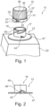
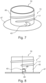
- eine perspektivische Ansicht eines Ausgiesselements in einer fünften Ausführungsform, welches mit der Verschlusskappe aus
Figur 6 zusammenwirkt; - Figur 8:
- eine Seitenansicht des Ausgiesselements aus
Figur 7 in einer Seitenansicht, wobei eine daran ausgebildete Ausnehmung in einer Schnittdarstellung gezeigt ist; - Figur 9:
- eine perspektivische Ansicht eines Ausgiesselements in einer sechsten Ausführungsform, welches mit der Verschlusskappe aus
Figur 6 zusammenwirkt; - Figur 10:
- eine Seitenansicht des Ausgiesselements aus
Figur 9 in einer Seitenansicht, wobei ein daran ausgebildeter Ring in einer Schnittdarstellung gezeigt ist und - Figur 11:
- eine siebente Ausführungsform des Behälterverschlusses in einer perspektivischen Ansicht.
- In den
Figuren 1 ,4 , und11 ist ein Behälterverschluss gezeigt, welcher gesamthaft mit dem Bezugszeichen 11 bezeichnet ist. Der Behälterverschluss 11 weist ein Ausgiesselement 13 und eine Verschlusskappe 15 auf. An der Aussenseite des Ausgiesselements 13 ist ein Aussengewinde 17 ausgebildet. Das Ausgiesselement 13 umschliesst eine Ausgiessöffnung 19, durch welche der Inhalt eines Behälters ausgegossen werden kann. Der Behälter kann ein Kunststoffbehälter 21 oder ein Getränkekarton 23 sein. Der Kunststoffbehälter kann aus einem Preform 25 hergestellt sein. Im Fall eines Kunststoffbehälters 21 ist das Ausgiesselement 13 ein integraler Bestandteil des Kunststoffbehälters 21 und besteht aus demselben Material wie der gesamte Kunststoffbehälter. Im Fall eines Getränkekartons 23, welcher aus einem Verbundwerkstoff hergestellt sein kann, ist das Ausgiesselement 13 an diesem befestigt, beispielsweise angeklebt. - Die Verschlusskappe 15 weist einen zylindrischen Gewindeteil 27 auf. Der zylindrische Gewindeteil 27 besitzt ein Innengewinde (in den Figuren nicht sichtbar), welches mit dem Aussengewinde 17 zusammenwirkt. Die Verschlusskappe 15 lässt sich daher auf das Ausgiesselement 13 aufschrauben und verschliesst im aufgeschraubten Zustand die Ausgiessöffnung 19. Das zylindrische Gewindeteil 27 weist einen offene Rand 29 auf, welcher dem Ausgiesselement 13 zugewandt ist. 1. Die Verschlusskappe ist aus einem Kunststoffmaterial, bevorzugt PP oder HDPE gefertigt.
- An dem offenen Rand 29 ist ein Garantieband 31 angeordnet, welches den Zweck erfüllt anzuzeigen, ob der Behälterverschluss 11 originalverschlossen ist oder nicht. Das Garantieband 31 ist in bekannter Weise mit einer Mehrzahl von Sollbruchstegen 33 an dem offenen Rand 29 befestigt. Beim Verdrehen der Verschlusskappe 15 in Öffnungsrichtung relativ zu dem Ausgiesselement 13 brechen die Sollbruchstege 33. Die gebrochenen bzw. gerissenen Sollbruchstege 33 lassen im geschlossenen Zustand des Behälterverschlusses 11 erkennen, dass der Behälterverschluss 11 bereits geöffnet wurde.
- Ziel der Erfindung ist es sicher zu stellen, dass die Verschlusskappe 15 unverlierbar auch nach Abschrauben von dem Ausgiesselement 13 an dem Ausgiesselement 13 gehalten ist und möglichst wenig Material für die vorgeschlagene Lösung benötigt wird.
- Das Garantieband 31 weist ein erstes Ende 35 und ein zweites Ende 37 auf. Im Vergleich zu einem Garantieband gemäss dem Stand der Technik, welches einen Ring ohne einem ersten und zweiten Ende ist, besitzt das vorliegende Garantiband 31 eine Aussparung 39. Auf der einen Seite der Aussparung 39 ist das erste Ende 35 gebildet und auf der gegenüberliegenden Seite der Aussparung 39 ist das zweite Ende 37 gebildet. Das erste Ende 35 ist fest mit dem offenen Rand 29 verbunden. Unter "fest verbunden" ist eine Verbindung zu verstehen, welche beim Öffnen der Verschlusskappe 15 nicht abreisst. Daher bleibt die Verschlusskappe 15 mit dem Garantieband 31 verbunden, auch wenn die Verschlusskappe 15 von dem Ausgiesselement 13 abgeschraubt ist. Beispielsweise kann das erste Ende 35 mit einem Steg an dem offenen Rand 29 befestigt sein.
- In einer ersten Ausführungsform gemäss den
Figuren 1 und 2 ist an dem zweiten Ende 37 ein erster Haken 41 ausgebildet. Der erste Haken 41 ist dazu vorgesehen, dass er in einer ersten Ausnehmung 43 verrastbar ist. Die erste Ausnehmung 43 ist an dem Ausgiesselement 13 derart angeordnet und ausgebildet, dass der erste Haken 41 in der ersten Ausnehmung 43 verrastbar ist. Das Ausgiesselement 13 weist einen Hals 45 und einen an den Hals anschliessenden Kragen 47 auf. In denFiguren 1 und 2 ist die Ausnehmung 43 am Übergang vom Hals 45 zu dem Kragen 47 an dem Kragen 47 ausgeformt. Wird die Verschlusskappe 15 in Öffnungsrichtung, also zumeist gegen den Uhrzeigersinn gedreht, so ist die erste Ausnehmung derart an dem Kragen 47 angeordnet, dass der erste Haken 41 in die erste Ausnehmung 43 eindringen muss. Die Ausnehmung 43 liegt daher in einer Ebene, welche orthogonal zum Hals 45 und zum Kragen 47 orientiert ist bzw. quer zum ersten Haken 41 orientiert ist. Wie inFigur 2 gezeigt ist, ist an der ersten Ausnehmung 43 ein Vorsprung 49 bzw. ein Widerhaken 49 ausgebildet, mit welchem der erste Haken 41 verrastet und formschlüssig in der ersten Ausnehmung gehalten ist. Beim weiteren Verdrehen der Verschlusskappe 15 wird das Garantieband 31 auf Schub belastet und die Sollbruchstege 33 brechen. Nach dem Abschrauben der Verschlusskappe 15 von dem Ausgiesselement 13 ist daher die Verschlusskappe 15 durch das Zusammenwirken des ersten Hakens 41 und der ersten Ausnehmung 43 unverlierbar über das Garantieband 31 an dem Ausgiesselement 13 gehalten. Bevorzugt ist es, wenn sich der erste Haken 41 aus der ersten Ausnehmung 43 nur mehr unter Zerstörung entfernen lässt, wenn er einmal in der ersten Ausnehmung 43 verrastet ist. - Es versteht sich, dass das Ausgiesselement 13 mitsamt der ersten Ausnehmung 43 auch an dem Preform 25 ausgebildet sein kann (
Figur 3 ) und integraler Bestandteil des Preforms 25 ist. Beim Streckblasen, beispielsweise zum Kunststoffbehälter 21, bleibt das Ausgiesselement 13 unverändert und wirkt mit der Verschlusskappe 15 genauso zusammen wie bei der Ausführungsform gemäss derFiguren 1 und 2 . - In der dritten Ausführungsform gemäss den
Figuren 4 und5 ist an dem Hals 45 wenigstens ein Führungselement in Gestalt einer rampenförmigen Erhebung 51 ausgebildet. Bei dieser Ausführungsform liegt die erste Ausnehmung 43 in der Ebene des Kragens 47 bzw. ist innerhalb des Kragens vorgesehen. Bei Verdrehung der Verschlusskappe 15 in Öffnungsrichtung wird der erste Haken 41 entlang der Erhebung 51 nach unten in Richtung der ersten Ausnehmung 43 geführt und in die erste Ausnehmung 43 gedrückt. In der ersten Ausnehmung verrastet der Haken 41 mit dem Widerhaken 49. - In der
Figur 4 ist gezeigt, dass das erste und zweite Ende 35, 37 des Garantiebandes 31 mit einem Garantiesteg 53 verbunden sind. Wird der erste Haken 41 von der Erhebung 51 nach unten gezwungen, so reisst der Garantiesteg 53 und zeigt an, dass der Behälterverschluss 11 nicht mehr originalverschlossen ist. Der Garantiesteg 53 ist bei der dritten Ausführungsform vorgesehen, da es denkbar ist, die Verschlusskappe 15 von dem Ausgiesselement 13 abzunehmen, ohne dass die Sollbruchstege 33 zerstört werden. In derFigur 4 ist die Breite der ersten Ausnehmung 43 im Bereich des Widerhakens 49 mit "A" bezeichnet. Die Breite des ersten Hakens 41 am Übergang zu dem Garantieband 31 ist mit "B" bezeichnet. Dadurch, dass die Breite B grösser ist als die Breite A wird der Widerhaken 49 von dem ersten Haken 41 nach oben gedrückt und vorgespannt, wenn der erste Haken 41 in die erste Ausnehmung 43 hineingedreht wird. Dadurch ist der erste Haken 41 zuverlässig in der ersten Ausnehmung 43 gehalten. - Ist an dem Ausgiesselement 13 ein mehrgängiges Aussengewinde 17 vorgesehen, so ist pro Gewinde eine erste Ausnehmung 43 und eine Erhebung 51 vorgesehen, damit der erste Haken 41 jedenfalls beim Öffnen der Verschlusskappe 15 in einer der ersten Öffnungen 43 verhakt.
- In einer vierten Ausführungsform gemäss der
Figur 6 ist der erste Haken 41 derart ausgebildet, dass er nicht nach unten in Richtung des Kragens 47 geführt ist, sondern zur Seite in Richtung des Halses 45. In diesem Fall ist die erste Ausnehmung 43 an dem Hals 45 derart ausgebildet, dass die Ausnehmung in einer zum Kragen 47 und zum Hals 45 orthogonal orientierten Ebene liegt. Wie inFigur 7 gezeigt, ist es durch die Orientierung der ersten Ausnehmung 43 möglich, dass der erste Haken 41 beim Verdrehen der Verschlusskappe 15 in Öffnungsrichtung in die erste Ausnehmung 43 hineinverdreht wird. Der erste Haken 41 verhakt in den Widerhaken 49, welche die Schnittdarstellung in derFigur 8 zeigt. Diese Ausführungsform ist insbesondere für Ausgiesselemente 13 geeignet, welche aus LDPE hergestellt sind, da sich die Ausnehmung 43 im Extrusionsblasverfahren herstellen lässt, nach welchem Extrusionsblasverfahren LDPE verarbeitet wird. - Wie die
Figuren 9 und 10 zeigen, kann die erste Ausnehmung 43 auch von einem Ring 54 umschlossen sein, welcher Ring an dem Hals 45 ausgebildet ist. Beim Verdrehen des ersten Hakens 41 wird dieser in den Ring 54 gedrückt und verhakt in dem Ring 54. Damit der erste Haken 41 in dem Ring 54 verhaken kann, besitzt der Ring eine konische Ausnehmung 43, welche sich von dem ersten Haken 41 weg verjüngt. Diese Ausführungsform ist insbesondere für Ausgiesselemente 13 geeignet, welche aus PET hergestellt sind, da der Ring 54 spritzgegossen werden kann und daher beim Spritzgiessen eines Preforms aus PET hergestellt werden kann. - In einer weiteren Ausführungsform gemäss der
Figur 11 ist an dem zweiten Ende 37 eine zweite Ausnehmung 55 vorgesehen. An dem Hals 45 ist ein zweiter Haken 57 ausgebildet. Bei Verdrehen der Verschlusskappe 15 in Öffnungsrichtung verhakt die zweite Ausnehmung 55 mit dem zweiten Haken 57. Dadurch ist die Verschlusskappe 15 mit dem Garantieband 31 nach dem Abschrauben an dem Ausgiesselement 13 gehalten. - Dadurch, dass das Garantieband 31 an seinem zweiten Ende 37 an dem Ausgiesselement 13 gehalten ist, kann auf weitere Vorrichtungen, welche das Garantieband 31 an dem Ausgiesselement 13 halten, verzichtet werden. Ein Haltering, welcher das Ausgiesselement in Umfangsrichtung umschliesst und das Zurückhalten des Garantiebandes an dem Ausgiesselement beim Abschrauben der Verschlusskappe ermöglicht, ist aus dem Stand der Technik bekannt. Gemäss der vorliegenden Erfindung kann auf einen solchen Haltering an dem Ausgiesselement verzichtet werden. Dadurch lässt sich das für den Haltering benötigte Kunststoffmaterial einsparen.
-
- 11
- Behälterverschluss
- 13
- Ausgiesselement
- 15
- Verschlusskappe
- 17
- Aussengewinde
- 19
- Ausgiessöffnung
- 21
- Kunststoffbehälter
- 23
- Getränkekarton
- 25
- Preform
- 27
- Zylindrischer Gewindeteil
- 29
- Offener Rand des Gewindeteils
- 31
- Garantieband
- 33
- Sollbruchstege
- 35
- Erstes Ende des Garantiebandes
- 37
- Zweites Ende des Garantiebandes
- 39
- Aussparung
- 41
- Erster Haken, Garantieband-Haken
- 43
- Erste Ausnehmung, Ausgiesselement-Ausnehmung
- 45
- Hals
- 47
- Kragen
- 49
- Vorsprung, Widerhaken
- 51
- Rampenförmige Erhebung
- 53
- Garantiesteg
- A
- Breite der ersten Ausnehmung 43 im Bereich des Widerhakens 49
- B
- Breite des ersten Hakens 41 am Übergang zum Garantieband 31
- 54
- Ring
- 55
- Zweite Ausnehmung, Garantieband-Ausnehmung
- 57
- Zweiter Haken, Ausgiesselement-Haken
Claims (17)
- Behälterverschluss (11) aufweisend- ein Ausgiesselement (13), welches in einen Behälterkörper übergeht oder an einem Behälterkörper befestigbar ist,- wenigstens ein an dem Ausgiesselement (13) ausgebildetes Aussengewinde (17) und- eine Verschlusskappe (15) zum Verschliessen einer innerhalb des Ausgiesselementes (13) vorgesehenen Ausgiessöffnung (19),die Verschlusskappe (15) aufweisend- einen zylindrischen Gewindeteil (27) mit einem offenen Rand (29) und einem Innengewinde, welches mit dem Aussengewinde (17) des Ausgiesselementes (13) zusammenwirkt,- ein Garantieband (31), welches mit einer Mehrzahl von Sollbruchstegen (33) mit dem offenen Rand (29) des Gewindeteils (27) verbunden ist, wobei das erstmalige Öffnen des Behälterverschlusses (11) durch Bruch der Sollbruchstege (33) anzeigbar ist und das Garantieband (31) ein erstes und ein zweites Ende (35,37) aufweist, wobei das erste Ende (35) mit dem offenen Rand (29) des Gewindeteils (27) fest verbunden ist,dadurch gekennzeichnet,
dass das zweite Ende (37) mit dem Ausgiesselement (13) verbindbar ist. - Behälterverschluss (11) nach Anspruch 1, dadurch gekennzeichnet, dass das erste Ende (35) und das zweite Ende (37) des Garantiebandes (31) mit einem Garantiesteg (53) verbunden sind, welcher Garantiesteg (53) bei Verdrehung des Gewindeteils (27) in Öffnungsrichtung bricht.
- Behälterverschluss (11) nach Anspruch 1 oder 2, dadurch gekennzeichnet, dass das zweite Ende (37) des Garantiebandes (31) durch einen Formschluss mit dem Ausgiesselement (13) verbindbar ist.
- Behälterverschluss (11) nach einem der vorangehenden Ansprüche, dadurch gekennzeichnet, dass an dem zweiten Ende (37) des Garantiebandes (31) ein Garantieband-Haken (41) ausgebildet ist, welcher in wenigstens einer an dem Ausgiesselement (13) vorgesehenen dem Garantieband-Haken (41) zugewandten Ausgiesselement-Ausnehmung (43) verrastbar ist.
- Behälterverschluss (11) nach einem der vorangehenden Ansprüche, dadurch gekennzeichnet, dass das Ausgiesselement (13) einen Hals (45) und einen an den Hals (45) anschliessenden Kragen (47) ausgebildet hat.
- Behälterverschluss (11) nach Anspruch 4 oder 5, dadurch gekennzeichnet, dass die wenigstens eine Ausgiesselement-Ausnehmung (43) an dem Hals (45) oder an dem Kragen (47) derart ausgebildet ist, dass die Ausnehmung (43) in einer zum Kragen (47) und zum Hals (45) orthogonal orientierten Ebene liegt.
- Behälterverschluss (11) nach einem der Ansprüche 4 bis 6, dadurch gekennzeichnet, dass am Übergang vom ersten Ende (35) zu dem zweiten Ende (37) des Garantibandes eine Aussparung (39) derart ausgebildet ist, dass der Garantieband-Haken (41) bei Verdrehung des Gewindeteils (27) in Öffnungsrichtung in die wenigstens eine Ausgiesselement-Ausnehmung (43) verdrehbar ist.
- Behälterverschluss (11) nach einem der Ansprüche 5 bis 7, dadurch gekennzeichnet, dass an dem Hals (45) wenigstens ein Führungselement (51) ausgebildet ist, welches bei Verdrehung des Gewindeteils (27) in Öffnungsrichtung den Garantieband-Haken (41) in die wenigstens eine Ausgiesselement-Ausnehmung (43) führt.
- Behälterverschluss (11) nach Anspruch 8, dadurch gekennzeichnet, dass das Führungselement eine rampenförmiger Erhebung (51) ist, an welcher der Garantieband-Haken (41) durch Verdrehung des Gewindeteils (27) in Öffnungsrichtung nach unten in Richtung der wenigstens einen Ausgiesselement-Ausnehmung (43) führbar ist.
- Behälterverschluss (11) nach einem der Ansprüche 5 bis 9, dadurch gekennzeichnet, dass die wenigstens eine Ausgiesselement-Ausnehmung (43) an dem Kragen (47) derart ausgebildet ist, dass die Ausnehmung (43) in der Ebene des Kragens (47) liegt.
- Behälterverschluss (11) nach einem der Ansprüche 4 bis 10, dadurch gekennzeichnet, dass innerhalb der wenigstens einen Ausgiesselement-Ausnehmung (43) ein Widerhaken (49) ausgeformt ist, welcher mit dem Garantieband-Haken (41) unlösbar verhakbar ist.
- Behälterverschluss (11) nach einem der Ansprüche 1 bis 3, dadurch gekennzeichnet, dass an dem zweiten Ende (37) des Garantiebandes (31) eine Garantieband-Ausnehmung (55) vorgesehen ist, welche mit wenigstens einem an dem Ausgiesselement (13) ausgebildeten der Garantieband-Ausnehmung (55) zugewandten Ausgiesselement-Haken (57) verrastbar ist und die Garantieband-Ausnehmung (55) bei Verdrehung des Gewindeteils (27) in Öffnungsrichtung an dem wenigstens einen Ausgiesselement-Haken (57) verhakbar ist.
- Behälterverschluss (11) nach Anspruch 11 oder 12, dadurch gekennzeichnet, dass der wenigstens eine Ausgiesselment-Haken (57) an dem Hals (45) ausgeformt ist.
- Behälterverschluss (11) nach einem der Ansprüche 5 bis 13, dadurch gekennzeichnet, dass der Hals (45) frei von einem Haltering zur Halterung des Garantiebandes (31) an dem Ausgiesselement (13) ist.
- Behälterverschluss (11) nach einem der vorangehenden Ansprüche, dadurch gekennzeichnet, dass das Ausgiesselement (13) dazu vorgesehen ist an einem Getränkekarton (23) bzw. einem Behälter hergestellt aus einem Verbundwerkstoff befestigt zu sein oder dass das Ausgiesselement (13) dazu vorgesehen ist ein integraler Bestandteil eines Kunststoffbehälters (21) zu sein.
- Ausgiesselement (13) welches in einen Behälterkörper übergeht oder an einem Behälterkörper befestigbar ist, aufweisend- einen Hals (45),- einen an den Hals (45) anschliessenden Kragen (47),- wenigstens ein an dem Hals (45) ausgebildetes Aussengewinde (17) und- eine innerhalb des Ausgiesselementes (13) vorgesehene Ausgiessöffnung (19), wobei an dem Ausgiesselement (13) eine Ausgiesselement-Ausnehmung (43) vorgesehen ist, in welcher Ausnehmung (43) ein freies Ende (37) eines an einer Verschlusskappe (15) ausgebildeten Garantiebandes (31) verrastbar ist,dadurch gekennzeichnet,
dass an dem Hals (45) wenigstens ein Führungselement (51) ausgebildet ist, welches bei Verdrehung des Gewindeteils (27) in Öffnungsrichtung den Garantieband-Haken (41) in die wenigstens eine Ausgiesselement-Ausnehmung (43) führen kann. - Verschlusskappe (15) zum Verschliessen einer innerhalb eines Ausgiesselementes (13) vorgesehenen Ausgiessöffnung (19), aufweisend- einen zylindrischen Gewindeteil (27) mit einem offenen Rand (29) und einem Innengewinde, welches mit dem Aussengewinde (17) des Ausgiesselementes (13) zusammenwirkt und- ein Garantieband (31), welches mit einer Mehrzahl von Sollbruchstegen (33) mit dem offenen Rand (29) des Gewindeteils (27) verbunden ist, wobei das erstmalige Öffnen eines Behälterverschlusses (11) durch Bruch der Sollbruchstege (33) anzeigbar ist, wobei das Garantieband (31) ein erstes und ein zweites Ende (35,37) aufweist und das erste Ende (35) mit dem offenen Rand (29) des Gewindeteils (27) fest verbunden ist und das zweite Ende (37) mit dem Ausgiesselement (13) verbindbar ist,dadurch gekennzeichnet,- dass an dem zweiten Ende (37) des Garantiebandes (31) ein Garantieband-Haken (41) ausgebildet ist, welcher in wenigstens einer an dem Ausgiesselement (13) vorgesehenen dem Garantieband-Haken (41) zugewandten Ausgiesselement-Ausnehmung (43) verrastbar ist oder- dass an dem zweiten Ende (37) des Garantiebandes (31) eine Garantieband-Ausnehmung (55) vorgesehen ist, welche mit wenigstens einem an dem Ausgiesselement (13) ausgebildeten der Garantieband-Ausnehmung (55) zugewandten Ausgiesselement-Haken (57) verrastbar ist.
Applications Claiming Priority (2)
| Application Number | Priority Date | Filing Date | Title |
|---|---|---|---|
| CH00326/19A CH715934A1 (de) | 2019-03-15 | 2019-03-15 | Behälterverschluss mit einem Ausgiesselement und einer unverlierbar gehaltenen Verschlusskappe. |
| PCT/EP2020/056947 WO2020187781A1 (de) | 2019-03-15 | 2020-03-13 | Behälterverschluss |
Publications (3)
| Publication Number | Publication Date |
|---|---|
| EP3938290A1 EP3938290A1 (de) | 2022-01-19 |
| EP3938290B1 true EP3938290B1 (de) | 2024-05-01 |
| EP3938290C0 EP3938290C0 (de) | 2024-05-01 |
Family
ID=65903847
Family Applications (1)
| Application Number | Title | Priority Date | Filing Date |
|---|---|---|---|
| EP20712497.5A Active EP3938290B1 (de) | 2019-03-15 | 2020-03-13 | Behälterverschluss |
Country Status (5)
| Country | Link |
|---|---|
| US (1) | US12371231B2 (de) |
| EP (1) | EP3938290B1 (de) |
| AR (1) | AR118370A1 (de) |
| CH (1) | CH715934A1 (de) |
| WO (1) | WO2020187781A1 (de) |
Families Citing this family (2)
| Publication number | Priority date | Publication date | Assignee | Title |
|---|---|---|---|---|
| EP4098574A1 (de) * | 2021-06-03 | 2022-12-07 | SIG Combibloc Services AG | Verschluss für einen behälter mit kontrollierter erstöffnung |
| DE102022111669A1 (de) * | 2022-05-10 | 2023-11-16 | Georg Menshen Gmbh & Co. Kg | Ausgießvorrichtung |
Family Cites Families (14)
| Publication number | Priority date | Publication date | Assignee | Title |
|---|---|---|---|---|
| US2039385A (en) * | 1934-01-24 | 1936-05-05 | Jacques R Bonhomme | Container and closure therefor |
| US4567991A (en) * | 1984-10-12 | 1986-02-04 | Sunbeam Plastics Corporation | Tamper indicating child resistant closure |
| CH672109A5 (de) * | 1987-01-30 | 1989-10-31 | Wiedmer Plastikform W | |
| US5111947A (en) * | 1990-12-04 | 1992-05-12 | Patterson Michael C | Tamper proof cap and container |
| US5040692A (en) * | 1990-12-17 | 1991-08-20 | Sunbeam Plastics Corporation | Tamper indicating closure |
| US5056675A (en) * | 1991-01-18 | 1991-10-15 | Sunbeam Plastics Corporation | Tether web ratchet drive tamper indicating band closure |
| DE9318243U1 (de) | 1993-11-29 | 1994-02-10 | Crown Cork Ag, Reinach | Kunststoff-Schraubkappe mit Garantieband und Fangband |
| AUPM505594A0 (en) * | 1994-04-15 | 1994-05-05 | G.V. Engineering Pty. Ltd. | Tamper evident closure |
| US5725115A (en) * | 1995-02-21 | 1998-03-10 | Crown Cork Ag | Closure cap with tether |
| NZ315543A (en) * | 1995-08-30 | 1998-08-26 | Gv Eng Pty Ltd | Tamper evident closure |
| US5992657A (en) * | 1998-05-28 | 1999-11-30 | Rexam Plastics Inc. | Safety closure having tamper-indicating means |
| EP1650135A1 (de) * | 2003-07-22 | 2006-04-26 | Barangüa, S.L. | Schraubkappe für behälter |
| KR20060090211A (ko) * | 2006-07-21 | 2006-08-10 | 이승준 | 병뚜껑의 이탈방지구조 |
| DE102007010786B4 (de) | 2007-03-02 | 2014-12-11 | Georg Menshen Gmbh & Co. Kg | Verschluss eines Behälters mit Originalitätsring |
-
2019
- 2019-03-15 CH CH00326/19A patent/CH715934A1/de not_active Application Discontinuation
-
2020
- 2020-03-13 EP EP20712497.5A patent/EP3938290B1/de active Active
- 2020-03-13 WO PCT/EP2020/056947 patent/WO2020187781A1/de not_active Ceased
- 2020-03-13 AR ARP200100725A patent/AR118370A1/es active IP Right Grant
- 2020-03-13 US US17/438,863 patent/US12371231B2/en active Active
Also Published As
| Publication number | Publication date |
|---|---|
| AR118370A1 (es) | 2021-09-29 |
| US12371231B2 (en) | 2025-07-29 |
| US20220144500A1 (en) | 2022-05-12 |
| WO2020187781A1 (de) | 2020-09-24 |
| EP3938290C0 (de) | 2024-05-01 |
| CH715934A1 (de) | 2020-09-15 |
| EP3938290A1 (de) | 2022-01-19 |
Similar Documents
| Publication | Publication Date | Title |
|---|---|---|
| DE69323423T2 (de) | Gegen manipulation gesicherter schraubverschluss | |
| EP0593396B1 (de) | Garantieverschluss aus Kunststoff | |
| DE2910178C2 (de) | Originalitäts-Schraubverschluß für Flaschen u.dgl | |
| DE2906812C2 (de) | ||
| DE69623459T2 (de) | Zum Zeitpunkt der Entsorgung von einer Flasche trennbare Kappe | |
| DE69702672T2 (de) | Kappe zum verschluss einer behälteröffnung | |
| EP0254673B1 (de) | Sicherheitsband an einem Gebindeverschluss | |
| EP2906475B1 (de) | Verschlusskappe, behälterhals, garantieverschluss sowie verfahren zur herstellung eines garantieverschlusses | |
| DE9318243U1 (de) | Kunststoff-Schraubkappe mit Garantieband und Fangband | |
| DE102007029541A1 (de) | Verschlusskappe mit Originalitätsband | |
| EP3938289B1 (de) | Verschlusskappe zum verschliessen eines behälters | |
| EP0951428B1 (de) | Flaschen-schraubverschluss aus kunststoff mit garantieband | |
| EP0243531A2 (de) | Sicherungsring für Flaschen-, Weithals- o.ä. Behälterverschlüsse | |
| DE2753080C2 (de) | Verschlußkappe mit Originalitätssicherung | |
| EP3938290B1 (de) | Behälterverschluss | |
| EP0451102B1 (de) | Verschlusskappe aus Kunststoff | |
| EP0371920A2 (de) | Schraubkappe mit Garantieband | |
| EP1926669A1 (de) | Garantieschraubverschluss für behälter und flaschen, insbesondere für kunststoffflaschen | |
| DE2638351C3 (de) | Garantieverschluß für Flaschen | |
| CH716870A2 (de) | Behälterverschluss. | |
| EP1529005B1 (de) | Verschluss/ausgiess-kombination mit originalit tssicherung | |
| EP0103567A2 (de) | Schraubkappe aus Kunststoff und Vorrichtung zum Verschliessen eines Behälters mit derselben | |
| DE2439414A1 (de) | Kunststoffverschluss fuer flaschen und behaelter | |
| EP1140646A1 (de) | Scharnierverschluss mit garantieelement | |
| DE102020108181A1 (de) | Vorrichtung zur austauschbaren Befestigung von Formatteilen |
Legal Events
| Date | Code | Title | Description |
|---|---|---|---|
| STAA | Information on the status of an ep patent application or granted ep patent |
Free format text: STATUS: UNKNOWN |
|
| STAA | Information on the status of an ep patent application or granted ep patent |
Free format text: STATUS: THE INTERNATIONAL PUBLICATION HAS BEEN MADE |
|
| PUAI | Public reference made under article 153(3) epc to a published international application that has entered the european phase |
Free format text: ORIGINAL CODE: 0009012 |
|
| STAA | Information on the status of an ep patent application or granted ep patent |
Free format text: STATUS: REQUEST FOR EXAMINATION WAS MADE |
|
| 17P | Request for examination filed |
Effective date: 20211014 |
|
| AK | Designated contracting states |
Kind code of ref document: A1 Designated state(s): AL AT BE BG CH CY CZ DE DK EE ES FI FR GB GR HR HU IE IS IT LI LT LU LV MC MK MT NL NO PL PT RO RS SE SI SK SM TR |
|
| DAV | Request for validation of the european patent (deleted) | ||
| DAX | Request for extension of the european patent (deleted) | ||
| GRAP | Despatch of communication of intention to grant a patent |
Free format text: ORIGINAL CODE: EPIDOSNIGR1 |
|
| STAA | Information on the status of an ep patent application or granted ep patent |
Free format text: STATUS: GRANT OF PATENT IS INTENDED |
|
| INTG | Intention to grant announced |
Effective date: 20231103 |
|
| GRAS | Grant fee paid |
Free format text: ORIGINAL CODE: EPIDOSNIGR3 |
|
| GRAA | (expected) grant |
Free format text: ORIGINAL CODE: 0009210 |
|
| STAA | Information on the status of an ep patent application or granted ep patent |
Free format text: STATUS: THE PATENT HAS BEEN GRANTED |
|
| AK | Designated contracting states |
Kind code of ref document: B1 Designated state(s): AL AT BE BG CH CY CZ DE DK EE ES FI FR GB GR HR HU IE IS IT LI LT LU LV MC MK MT NL NO PL PT RO RS SE SI SK SM TR |
|
| REG | Reference to a national code |
Ref country code: GB Ref legal event code: FG4D Free format text: NOT ENGLISH |
|
| REG | Reference to a national code |
Ref country code: CH Ref legal event code: EP |
|
| REG | Reference to a national code |
Ref country code: DE Ref legal event code: R096 Ref document number: 502020007853 Country of ref document: DE |
|
| REG | Reference to a national code |
Ref country code: IE Ref legal event code: FG4D Free format text: LANGUAGE OF EP DOCUMENT: GERMAN |
|
| U01 | Request for unitary effect filed |
Effective date: 20240521 |
|
| U07 | Unitary effect registered |
Designated state(s): AT BE BG DE DK EE FI FR IT LT LU LV MT NL PT SE SI Effective date: 20240603 |
|
| PG25 | Lapsed in a contracting state [announced via postgrant information from national office to epo] |
Ref country code: IS Free format text: LAPSE BECAUSE OF FAILURE TO SUBMIT A TRANSLATION OF THE DESCRIPTION OR TO PAY THE FEE WITHIN THE PRESCRIBED TIME-LIMIT Effective date: 20240901 |
|
| PG25 | Lapsed in a contracting state [announced via postgrant information from national office to epo] |
Ref country code: HR Free format text: LAPSE BECAUSE OF FAILURE TO SUBMIT A TRANSLATION OF THE DESCRIPTION OR TO PAY THE FEE WITHIN THE PRESCRIBED TIME-LIMIT Effective date: 20240501 |
|
| PG25 | Lapsed in a contracting state [announced via postgrant information from national office to epo] |
Ref country code: GR Free format text: LAPSE BECAUSE OF FAILURE TO SUBMIT A TRANSLATION OF THE DESCRIPTION OR TO PAY THE FEE WITHIN THE PRESCRIBED TIME-LIMIT Effective date: 20240802 |
|
| PG25 | Lapsed in a contracting state [announced via postgrant information from national office to epo] |
Ref country code: ES Free format text: LAPSE BECAUSE OF FAILURE TO SUBMIT A TRANSLATION OF THE DESCRIPTION OR TO PAY THE FEE WITHIN THE PRESCRIBED TIME-LIMIT Effective date: 20240501 |
|
| PG25 | Lapsed in a contracting state [announced via postgrant information from national office to epo] |
Ref country code: PL Free format text: LAPSE BECAUSE OF FAILURE TO SUBMIT A TRANSLATION OF THE DESCRIPTION OR TO PAY THE FEE WITHIN THE PRESCRIBED TIME-LIMIT Effective date: 20240501 |
|
| PG25 | Lapsed in a contracting state [announced via postgrant information from national office to epo] |
Ref country code: PL Free format text: LAPSE BECAUSE OF FAILURE TO SUBMIT A TRANSLATION OF THE DESCRIPTION OR TO PAY THE FEE WITHIN THE PRESCRIBED TIME-LIMIT Effective date: 20240501 Ref country code: NO Free format text: LAPSE BECAUSE OF FAILURE TO SUBMIT A TRANSLATION OF THE DESCRIPTION OR TO PAY THE FEE WITHIN THE PRESCRIBED TIME-LIMIT Effective date: 20240801 Ref country code: IS Free format text: LAPSE BECAUSE OF FAILURE TO SUBMIT A TRANSLATION OF THE DESCRIPTION OR TO PAY THE FEE WITHIN THE PRESCRIBED TIME-LIMIT Effective date: 20240901 Ref country code: HR Free format text: LAPSE BECAUSE OF FAILURE TO SUBMIT A TRANSLATION OF THE DESCRIPTION OR TO PAY THE FEE WITHIN THE PRESCRIBED TIME-LIMIT Effective date: 20240501 Ref country code: GR Free format text: LAPSE BECAUSE OF FAILURE TO SUBMIT A TRANSLATION OF THE DESCRIPTION OR TO PAY THE FEE WITHIN THE PRESCRIBED TIME-LIMIT Effective date: 20240802 Ref country code: ES Free format text: LAPSE BECAUSE OF FAILURE TO SUBMIT A TRANSLATION OF THE DESCRIPTION OR TO PAY THE FEE WITHIN THE PRESCRIBED TIME-LIMIT Effective date: 20240501 Ref country code: RS Free format text: LAPSE BECAUSE OF FAILURE TO SUBMIT A TRANSLATION OF THE DESCRIPTION OR TO PAY THE FEE WITHIN THE PRESCRIBED TIME-LIMIT Effective date: 20240801 |
|
| PG25 | Lapsed in a contracting state [announced via postgrant information from national office to epo] |
Ref country code: CZ Free format text: LAPSE BECAUSE OF FAILURE TO SUBMIT A TRANSLATION OF THE DESCRIPTION OR TO PAY THE FEE WITHIN THE PRESCRIBED TIME-LIMIT Effective date: 20240501 |
|
| PG25 | Lapsed in a contracting state [announced via postgrant information from national office to epo] |
Ref country code: RO Free format text: LAPSE BECAUSE OF FAILURE TO SUBMIT A TRANSLATION OF THE DESCRIPTION OR TO PAY THE FEE WITHIN THE PRESCRIBED TIME-LIMIT Effective date: 20240501 Ref country code: SK Free format text: LAPSE BECAUSE OF FAILURE TO SUBMIT A TRANSLATION OF THE DESCRIPTION OR TO PAY THE FEE WITHIN THE PRESCRIBED TIME-LIMIT Effective date: 20240501 |
|
| PG25 | Lapsed in a contracting state [announced via postgrant information from national office to epo] |
Ref country code: SM Free format text: LAPSE BECAUSE OF FAILURE TO SUBMIT A TRANSLATION OF THE DESCRIPTION OR TO PAY THE FEE WITHIN THE PRESCRIBED TIME-LIMIT Effective date: 20240501 |
|
| PG25 | Lapsed in a contracting state [announced via postgrant information from national office to epo] |
Ref country code: SM Free format text: LAPSE BECAUSE OF FAILURE TO SUBMIT A TRANSLATION OF THE DESCRIPTION OR TO PAY THE FEE WITHIN THE PRESCRIBED TIME-LIMIT Effective date: 20240501 Ref country code: SK Free format text: LAPSE BECAUSE OF FAILURE TO SUBMIT A TRANSLATION OF THE DESCRIPTION OR TO PAY THE FEE WITHIN THE PRESCRIBED TIME-LIMIT Effective date: 20240501 Ref country code: RO Free format text: LAPSE BECAUSE OF FAILURE TO SUBMIT A TRANSLATION OF THE DESCRIPTION OR TO PAY THE FEE WITHIN THE PRESCRIBED TIME-LIMIT Effective date: 20240501 Ref country code: CZ Free format text: LAPSE BECAUSE OF FAILURE TO SUBMIT A TRANSLATION OF THE DESCRIPTION OR TO PAY THE FEE WITHIN THE PRESCRIBED TIME-LIMIT Effective date: 20240501 |
|
| REG | Reference to a national code |
Ref country code: DE Ref legal event code: R097 Ref document number: 502020007853 Country of ref document: DE |
|
| PLBE | No opposition filed within time limit |
Free format text: ORIGINAL CODE: 0009261 |
|
| STAA | Information on the status of an ep patent application or granted ep patent |
Free format text: STATUS: NO OPPOSITION FILED WITHIN TIME LIMIT |
|
| 26N | No opposition filed |
Effective date: 20250204 |
|
| PGFP | Annual fee paid to national office [announced via postgrant information from national office to epo] |
Ref country code: GB Payment date: 20250324 Year of fee payment: 6 |
|
| U20 | Renewal fee for the european patent with unitary effect paid |
Year of fee payment: 6 Effective date: 20250325 |
|
| PGFP | Annual fee paid to national office [announced via postgrant information from national office to epo] |
Ref country code: CH Payment date: 20250401 Year of fee payment: 6 |
|
| PG25 | Lapsed in a contracting state [announced via postgrant information from national office to epo] |
Ref country code: MC Free format text: LAPSE BECAUSE OF FAILURE TO SUBMIT A TRANSLATION OF THE DESCRIPTION OR TO PAY THE FEE WITHIN THE PRESCRIBED TIME-LIMIT Effective date: 20240501 |