EP0450877A2 - Rotationszerstäuber mit integrierter Farbwechselvorrichtung und Fluiddruckregler - Google Patents
Rotationszerstäuber mit integrierter Farbwechselvorrichtung und Fluiddruckregler Download PDFInfo
- Publication number
- EP0450877A2 EP0450877A2 EP91302777A EP91302777A EP0450877A2 EP 0450877 A2 EP0450877 A2 EP 0450877A2 EP 91302777 A EP91302777 A EP 91302777A EP 91302777 A EP91302777 A EP 91302777A EP 0450877 A2 EP0450877 A2 EP 0450877A2
- Authority
- EP
- European Patent Office
- Prior art keywords
- colour
- coating material
- valve
- fluid
- rotary atomiser
- Prior art date
- Legal status (The legal status is an assumption and is not a legal conclusion. Google has not performed a legal analysis and makes no representation as to the accuracy of the status listed.)
- Granted
Links
- 239000012530 fluid Substances 0.000 title claims abstract description 59
- 239000000463 material Substances 0.000 claims abstract description 117
- 238000000576 coating method Methods 0.000 claims abstract description 98
- 239000011248 coating agent Substances 0.000 claims abstract description 97
- 230000008859 change Effects 0.000 claims abstract description 21
- 230000000295 complement effect Effects 0.000 claims description 2
- 239000002904 solvent Substances 0.000 abstract description 32
- 238000005507 spraying Methods 0.000 abstract description 13
- 238000011010 flushing procedure Methods 0.000 abstract description 12
- 238000009434 installation Methods 0.000 abstract 1
- 230000008878 coupling Effects 0.000 description 14
- 238000010168 coupling process Methods 0.000 description 14
- 238000005859 coupling reaction Methods 0.000 description 14
- 239000007788 liquid Substances 0.000 description 8
- 239000003086 colorant Substances 0.000 description 7
- 230000002829 reductive effect Effects 0.000 description 7
- 210000004907 gland Anatomy 0.000 description 6
- 239000007921 spray Substances 0.000 description 6
- 239000012811 non-conductive material Substances 0.000 description 5
- 230000000694 effects Effects 0.000 description 4
- 239000003973 paint Substances 0.000 description 4
- 230000004044 response Effects 0.000 description 4
- 238000000889 atomisation Methods 0.000 description 3
- 230000000875 corresponding effect Effects 0.000 description 3
- 238000012856 packing Methods 0.000 description 3
- 230000002093 peripheral effect Effects 0.000 description 3
- 238000010926 purge Methods 0.000 description 3
- 239000002699 waste material Substances 0.000 description 3
- 230000008901 benefit Effects 0.000 description 2
- 238000010276 construction Methods 0.000 description 2
- 230000003247 decreasing effect Effects 0.000 description 2
- 230000036961 partial effect Effects 0.000 description 2
- 230000000717 retained effect Effects 0.000 description 2
- 230000009471 action Effects 0.000 description 1
- 230000000903 blocking effect Effects 0.000 description 1
- 238000004140 cleaning Methods 0.000 description 1
- 239000004020 conductor Substances 0.000 description 1
- 239000000356 contaminant Substances 0.000 description 1
- 238000011109 contamination Methods 0.000 description 1
- 230000001276 controlling effect Effects 0.000 description 1
- 230000002596 correlated effect Effects 0.000 description 1
- 230000000593 degrading effect Effects 0.000 description 1
- 230000000977 initiatory effect Effects 0.000 description 1
- 238000003780 insertion Methods 0.000 description 1
- 230000037431 insertion Effects 0.000 description 1
- 230000001788 irregular Effects 0.000 description 1
- 230000000670 limiting effect Effects 0.000 description 1
- 239000011344 liquid material Substances 0.000 description 1
- 230000007246 mechanism Effects 0.000 description 1
- 238000000034 method Methods 0.000 description 1
- 238000002360 preparation method Methods 0.000 description 1
- 238000007493 shaping process Methods 0.000 description 1
- 229910001220 stainless steel Inorganic materials 0.000 description 1
- 239000010935 stainless steel Substances 0.000 description 1
- 238000003860 storage Methods 0.000 description 1
- 231100000331 toxic Toxicity 0.000 description 1
- 230000002588 toxic effect Effects 0.000 description 1
- 238000011144 upstream manufacturing Methods 0.000 description 1
Images

Classifications
-
- B—PERFORMING OPERATIONS; TRANSPORTING
- B05—SPRAYING OR ATOMISING IN GENERAL; APPLYING FLUENT MATERIALS TO SURFACES, IN GENERAL
- B05B—SPRAYING APPARATUS; ATOMISING APPARATUS; NOZZLES
- B05B12/00—Arrangements for controlling delivery; Arrangements for controlling the spray area
- B05B12/14—Arrangements for controlling delivery; Arrangements for controlling the spray area for supplying a selected one of a plurality of liquids or other fluent materials or several in selected proportions to a spray apparatus, e.g. to a single spray outlet
- B05B12/1409—Arrangements for controlling delivery; Arrangements for controlling the spray area for supplying a selected one of a plurality of liquids or other fluent materials or several in selected proportions to a spray apparatus, e.g. to a single spray outlet the selection means being part of the discharge apparatus, e.g. part of the spray gun
-
- B—PERFORMING OPERATIONS; TRANSPORTING
- B05—SPRAYING OR ATOMISING IN GENERAL; APPLYING FLUENT MATERIALS TO SURFACES, IN GENERAL
- B05B—SPRAYING APPARATUS; ATOMISING APPARATUS; NOZZLES
- B05B12/00—Arrangements for controlling delivery; Arrangements for controlling the spray area
- B05B12/08—Arrangements for controlling delivery; Arrangements for controlling the spray area responsive to condition of liquid or other fluent material to be discharged, of ambient medium or of target ; responsive to condition of spray devices or of supply means, e.g. pipes, pumps or their drive means
- B05B12/085—Arrangements for controlling delivery; Arrangements for controlling the spray area responsive to condition of liquid or other fluent material to be discharged, of ambient medium or of target ; responsive to condition of spray devices or of supply means, e.g. pipes, pumps or their drive means responsive to flow or pressure of liquid or other fluent material to be discharged
- B05B12/087—Flow or presssure regulators, i.e. non-electric unitary devices comprising a sensing element, e.g. a piston or a membrane, and a controlling element, e.g. a valve
- B05B12/088—Flow or presssure regulators, i.e. non-electric unitary devices comprising a sensing element, e.g. a piston or a membrane, and a controlling element, e.g. a valve the sensing element being a flexible member, e.g. membrane, diaphragm, bellows
-
- B—PERFORMING OPERATIONS; TRANSPORTING
- B05—SPRAYING OR ATOMISING IN GENERAL; APPLYING FLUENT MATERIALS TO SURFACES, IN GENERAL
- B05B—SPRAYING APPARATUS; ATOMISING APPARATUS; NOZZLES
- B05B5/00—Electrostatic spraying apparatus; Spraying apparatus with means for charging the spray electrically; Apparatus for spraying liquids or other fluent materials by other electric means
- B05B5/025—Discharge apparatus, e.g. electrostatic spray guns
- B05B5/04—Discharge apparatus, e.g. electrostatic spray guns characterised by having rotary outlet or deflecting elements, i.e. spraying being also effected by centrifugal forces
- B05B5/0426—Means for supplying shaping gas
Definitions
- This invention relates to a rotary atomising liquid spray coating apparatus and more particularly to a rotary atomizer including a colour changer and an optional fluid pressure regulator both located within the housing of the rotary atomiser.
- rotary atomiser refers to a type of liquid spray coating apparatus which includes an atomiser head rotatable at high speed (typically 10,000-40,000 rpm) to effect atomisation of a liquid coating material to be applied to a work piece.
- the head is usually in the form of a disk or a cup which includes an interior wall defining a cavity and terminating in an atomising edge. Liquid coating material delivered to the interior of the cup migrates outwardly under centrifugal force along the wall until it is flung from the atomising edge of the cup and thereby atomised.
- US Patent 4887770 and the patents discussed below teach providing a valve for selectively flushing the cup and the line which feeds coating material to the cup, with solvent, in order to clean that line and the cup prior to changing colours or types of coating material.
- U.S. Patent No. 4,422,576 to Saito et al. discloses a colour change apparatus and method for an electrostatic rotary atomiser wherein a pair of colour change valve manifolds are located remotely from the rotary atomiser.
- Each manifold includes a plurality of individual colour valves whose outlets are connected to a common material feed line as well as valves for selectively delivery paint thinner and air into the feed line for flushing.
- the inlet of each colour valve is connected to a supply of coating material of a particular colour.
- Each of the common feed lines is connected to a first change-over valve which is mounted to the rotary atomiser in the high voltage region adjacent the rotary atomising head.
- the first change-over valve selectively couples one of the feed lines either to the rotary atomising head or to an inlet of an adjacent change-over valve by way of a first drain line.
- the second change-over valve includes another inlet connected to a second drain pipe and an outlet connected to a third drain pipe.
- the second drain pipe communicates with a shroud surrounding the atomising head, while the third drain pipe runs to a remotely located ejector valve.
- solvent is fed at high pressure and at a great flow rate, together with bursts of air, through: the feed line, the first change-over valve, the first drain pipe, the second change-over valve and finally to the ejector by way of the third drain pipe.
- the change-over valves are shifted to feed solvent to the atomising head from where the solvent collects in the shroud.
- the shroud drains via the second drain pipe and through the second change-over valve to the ejector valve by way of the third drain pipe.
- This system suffers the drawback of requiring flushing of the long paint lines between the colour changer and the change-over valves. This increases both the wastage of coating material and the amount of solvent required to flush the system sufficiently to avoid contaminating the next desired coating material with the colour used previously. Rapid and complete flushing is inhibited further owing to the circuitous coating material path which must be flushed. That path is not only long and voluminous but also includes areas of irregular shape and changing cross-section where coating material tends to accumulate.
- U.S. Patent No. 4,380,321 to Culbertson et al. discloses a colour change valve structure for a rotary atomiser which includes a coating material valve and a dump valve. Both valves are mounted in a single valve body which is located just behind the rotary atomising head.
- the coating material valve includes an inlet which is connected to a feed line carrying either coating material or flushing media from remotely located valves.
- the dump valve operates selectively to connect the feed line through the material valve to a dump outlet.
- the dump valve is opened and a flow of flushing media is established through the supply line to cleanse the supply line and material valve and expel waste through the dump outlet. Thereafter, the dump valve is closed and the material valve is momentarily opened to cleanse that portion of the coating material supply path located between the material valve and the atomising head to prepare for spraying material of the different colour.
- a rotary atomiser which is capable of spraying a plurality of colours without requiring the flushing of long coating material feed lines between the rotary atomiser and a common coating material feed line for supplying colours one at a time to the atomiser.
- a rotary atomiser wherein the portion of the coating material path which must be flushed is kept to a minimal volume and presents few, if any, regions wherein coating material may accumulate in pockets which are difficult to flush thoroughly.
- Positioning a pressure regulator remotely from the atomiser causes even further pressure regulation inaccuracy when a rotary atomiser is to be mounted on an oscillator having significant vertical travel.
- the pressure head between the regulator and the nozzle supplying the coating material to the atomising head will vary as a function of the vertical height of the atomiser.
- the atomiser will tend to deliver less coating material when raised than when the atomiser is in a lower position.
- While mounting a regulator remotely of the atomiser offers an advantage in that the regulator can be conveniently disconnected when not required for a particular job, such external mounting is bulky and exposes the regulator to overspray and other contaminating build up, particularly where the regulator is mounted inside a spray booth.
- a rotary atomiser which is compact and which includes a fluid pressure regulator mounted for improved flow rate control accuracy and improved response time, irrespective of the vertical position of the rotary atomiser.
- a rotary atomiser offering such improved control while protecting the regulator from a contaminating environment yet permitting the regulator to be conveniently disconnected and reconnected depending on the requirements of a particular coating job.
- a rotary atomiser in accordance with this invention comprises a housing, an atomising head rotatable about an axis and having a coating material flow surface which forms a forward cavity and which terminates at an atomising edge, fluid being supplied to the forward cavity, and a pressure regulator being provided in the feed to the forward cavity, characterised in that the fluid pressure regulator is located entirely within the housing.
- a colour changer is connected through the fluid pressure regulator to the fluid feed, the colour changer being located entirely within the housing.
- a rotary atomiser comprises a housing, an atomising head rotatable about an axis and having a coating material flow surface which forms a forward cavity and which terminates at an atomising edge, fluid being supplied to the forward cavity, and a colour changer being provided in the feed to the forward cavity, characterised in that the colour changer is located entirely within the housing.
- the colour changer manifold may include a plurality of independently actuatable valves each having an inlet and an outlet.
- the inlet of one of the valves is preferably connected to a supply of solvent while the remaining inlets are each coupled to a supply of a different colour or type of coating material.
- the outlets of all of the valves, including the one supplied with solvent, may be connected to a common discharge port which communicates with the rotary atomising head by way of a coating material flow path.
- the coating material flow path is both short in length and small in volume. Accordingly, coating material is conserved since only a small volume of material must be purged prior to changing to a different colour and/or type of material, thereby reducing the expense of coating operations. Also, the flow path may be flushed thoroughly with a minimal volume of solvent, thereby necessary expenditures for solvent are also reduced. Since both wasted coating material and used solvent can sometimes be toxic, reducing their generation helps to protect the environment and reduces disposal costs.
- the colour changer is preferably arranged so that its discharge port lies in substantially direct alignment with all or most of the coating material flow path between the colour changer and the atomising head, and which preferably coincides with the axis of rotation of the atomising head. This provides a substantially straight, readily flushable flow path between the colour changer and the atomising head.
- the colour changer may be adjustably positionable along the aforementioned axis.
- Such mounting provides for the easy connection of a pressure regulator between the discharge port of the colour changer and the atomising head.
- the pressure regulator which is preferably a type variable by remote control, may be mounted in close proximity to the atomising head so that the outlet pressure of the regulator correlates predictably with the pressure at which the atomiser head is supplied with coating material.
- the pressure regulator always remains at substantially the same elevation as the atomising head, even when the atomiser is raised and lowered by an oscillator when in use, flow variations due to changes in the height of the atomiser do not occur.
- Each of the valves in the colour changer manifold are mounted in a common body which is preferably of an electrically non-conductive material.
- the valves may be constructed identically to minimise spare parts requirements.
- the valves are preferably disposed in a radial array within the valve body such that the outlet of each valve lies closely adjacent the common discharge port to reduce even further the length and the volume of the portion of the flow path which must be flushed prior to a colour change.
- the inlet of one of the valves of the colour change manifold can be connected to a supply of solvent while the remaining valves each receive a different colour or type of coating material.
- either solvent or coating material of a particular colour is delivered to the atomising head by way of the discharge port.
- the valve supplying the first colour is first closed.
- the valve receiving a supply of solvent is opened in order to flush the first colour from the paint path between the onboard colour changer and the atomising head.
- the solvent valve is closed and a different valve connected to a supply of material of the second colour is opened.
- the invention normally provides for selecting among a number of colours equal to one less than the total number of valves in the onboard valve manifold.
- the invention has the flexibility to provide for an even greater number of colours by connecting one of the valves of the onboard colour changer to an external colour changer.
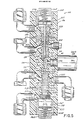
- Fig. 1 is a partial longitudinal cross-sectional view of a preferred embodiment of the present invention including an on board colour changer and an optional on board pressure regulator.
- Fig. 2 is an axial cross-sectional view along line 2-2 of Fig. 1.
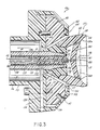
- Fig. 3 is a partial longitudinal cross-sectional view showing the forward end of the rotary atomiser of Fig. 1 in further detail.
- Fig. 4 is an axial view of the colour changer and its support along line 4-4 of Fig. 1.
- Fig. 5 is a cross-sectional view of a preferred embodiment of a colour changer in accordance with the present invention along lines 5-5 of Fig. 4.
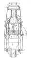
- Fig. 6 is a simplified longitudinal view of the rotary atomiser of Fig. 1, partly in cross-section as viewed along line 6-6 of Fig. 1. but having the fluid pressure regulator shown in Fig. 1 removed and having the colour changer of Fig. 1 axially repositioned to a more forward position.
- a rotary atomiser 10 includes a generally tubular housing 11 having a forward end 13 and a rearward end 15.
- Housing 11 is preferably constructed of electrically non-conductive material and defines an interior space 16 which is terminated at rearward end 15 by a support flange 18 which carries a hollow cylindrical extension 19 having locking means such as a bolt 20 for securing rotary atomizer 10 to a support member 22 which may be either fixed or movable.
- support member 22 may be attached to an oscillator (not shown) for moving rotary atomiser 10 along a predetermined path when it is in use.
- cap assembly 26 includes a tapered central recess 27 from which a rotary atomiser head in the form of a cup 29 extends.
- Cup 29 which will also be described in further detail hereinafter, includes a base 30 which is threadably secured to a shaft 31 having a frusto-conical portion 32. Shaft 31 extends from a motor 36 for rotating cup 29 at high speed about an axis 38.
- Motor 36 preferably comprises an air driven type turbine which includes internal air bearings, a driving air inlet and a braking air inlet for controlling the rotation of cup 29, all of which components are well known in the art and do not form a part of the invention.
- Motor 36 also has a bore 40 which is aligned with axis 38 and traverses the entire length of motor 36 and shaft 31.
- Shaft 31 extends from the rear of motor 36, where it is secured to turbine blades (not shown), out through the front of the motor 36 where the cup 29 is threadably secured thereto as previously described.
- a removable coating material feed tube 42 extends through bore 40.
- Feed tube 42 has a first end 44 which communicates with the interior of cup 29 and which preferably carries a removable nozzle 45 (see Fig. 3).
- Feed tube 42 further includes an opposed second end 47 having a female fluid coupling 49.
- Coupling 49 has a base 48 which is frictionally and removably received within the base 51 of motor 36. When engaged within base 51, base 48 supports feed tube 42 in cantilevered fashion free of contact from the wall of bore 40 thereby eliminating the need for a bearing between feed tube 42 and rotating components associated with motor 36.
- motor 36 is received within a motor housing 53 which is preferably formed of an electrically non-conductive material.
- Motor housing 53 has a forward end 54 secured to cap assembly 26 and a rearward end 55 which carries one or more clamps 57 engageable with the base 51 of motor 36 for holding motor 36 securely in place within motor housing 53 as shown.
- the base 51 of motor 36 includes a driving air inlet 60, a braking air inlet 61, a bearing air inlet 62 and an exhaust port 63, each connected to respective conduits (not shown) extending exteriorly of rotary atomiser 10 through a notch formed in flange 18.
- the rearward end 55 of motor housing 53 receives threaded ends 65 and 66 of a pair of parallel, spaced supports 67 and 68 only one of which 68, is partially visible in Fig.1 (see Fig. 6 also).
- Supports 67 and 68 each extend through the interior space 16 of housing 11 to support flange 18 and are generally perpendicular thereto.
- the respective second threaded ends 72, 73 of supports 67,68 extend through flange 18 and are secured relative to flange 18 by means of respective nuts 77 and 78.
- the rotatably atomiser 10 can be an electrostatic type adapted to impart an electrical charge to liquid coating material just prior to its atomisation. Accordingly, rotary atomiser 10 can be supplied with a high voltage by a high voltage cable (not shown) which would supply a high voltage to one or more charging electrodes for imparting a charge to the coating material in the manner described in U.S. Patent No. 4,887,770, which has previously been incorporated by reference herein.
- Cap assembly 26 includes a generally circular cap 98 which mates flush with the forward end 54 of motor housing 53 and is positionally located with respect thereto by means of a pin 99.
- Cap assembly 26 includes an electrically non-conductive cover 96 which is connected to cap 98 by means of a plurality of flat head screws 97.
- Cover 96 includes an annular groove 103 intersected by a plurality of small air ports 104 each of which is oriented in a direction generally parallel to rotational axis 38 (as shown in Fig. 3).
- Groove 103 is connected to an air line (not shown) to provide a plurality of jets which discharge from air ports 104 to assist in both shaping the spray of coating material discharged from atomising edge 114 and propelling the spray toward a work piece to be coated.
- the cup 29 in the preferred embodiment is formed of the base portion 30 and an end cap 110.
- Base 30 is removably threaded to the shaft 31 of motor 36 while end cap 110 is removably threaded to base 30.
- End cap 110 includes a divider 120 which defines a forward cup cavity 117 and a rearward cup cavity 118.
- divider 120 takes the form of a generally circular disk having a forward face which dishes inwardly toward its central portion.
- the peripheral portion of divider 120 at its rearward face, adjoins wall 112 and, at its forward face, adjoins a coating material flow surface 112a which terminates at an atomising edge 114.
- the periphery of divider 120 includes a plurality of circumferentially spaced holes 122. Holes 122 have inlets adjacent wall 112 and terminate adjacent coating material flow surface 112a thereby establishing flow paths through which most of the fluid entering rear cavity 118 makes its way to the coating material flow surface 112a which partially surrounds forward cup cavity 117. Also, the central portion of divider 120 is provided with a central opening 121 through which rearward cavity 118 can communicate with forward cavity 117. Preferably, opening 121 is formed of four separate, circumferentially spaced holes which intersect near the forward face of divider 120 but which diverge away from axis 38 so that coating material discharge from nozzle 45 is not aimed directly into opening 121.
- removable feed tube 42 comprises a first tube 130 having a reduced diameter end portion 131 which is adhesively bonded inside a recess formed inside a short second portion 133. Second portion 133 threadably receives a nozzle 45 having a central orifice 136 which communicates with the interior passageway 138 of removable feed tube 42.
- the size of central orifice 136 and/or interior passageway 138 can be varied by replacing nozzle 45 and/or feed tube 42 with ones having a central orifice 136 or interior passageway 138 respectively of a different size or diameter to provide desired flow characteristics.
- the first portion 130 of feed tube 42 is constructed of a rigid material such as stainless steel capable of being supported in cantilevered fashion as described earlier while the second portion 133 of feed tube 44 is preferably made of an electrically non-conductive material. Portions 130 and 133 of feed tube 42 are preferably covered with a layer of heat-shrinkable tubing 137.
- the rotary atomiser 10 of the invention includes a colour change valve manifold 140 as well as an optional fluid pressure regulator 145.
- Manifold 140 includes a discharge port 141 which can be connected to a fluid inlet 147 of regulator 145.
- Regulator 145 also includes a fluid outlet 148 and a control air inlet 150.
- the inlet 147 of regulator 145 receives a threaded end of a first rigid conduit 152 while its fluid outlet 148 receives a threaded end of a second rigid conduit 154.
- conduits 152 and 154 each include respective reduced diameter portions 156 and 157 opposite their threaded ends.
- Portions 156 and 157 each has a groove with a respective O-ring 159, 160 mounted therein.
- Reduced diameter portion 156 with its O-ring 159 fits snugly inside the wall of discharge port 141 in order to effect a fluid tight connection between discharge port 141 and first conduit 152.
- the reduced diameter portion 157 associated with second conduit 154 with its O-ring 160 likewise affects a snug and fluid tight connection with the female coupling 49 of removable feed tube 42.
- fluid pressure regulator 145 is preferably a remotely variable type and, in the preferred embodiment includes an upper housing 163 which threadably connects to a lower housing 164.
- a flexible diaphragm 166 is captured between upper housing 163 and lower housing 164 to define an upper cavity 168 above diaphragm 166 and a lower cavity 169 below diaphragm 166.
- Lower cavity 169 communicates with control air inlet 150 which is connected via an air line means (not shown) to a source of control air located remotely from rotary atomiser 10.
- Upper housing 163 is traversed by a bore 171 which includes a land which supports a valve seat 172.
- Seat 172 is clamped in place by means of a radially ported, inverted cup-shaped member 174 which extends downwardly from a threaded plug 175 fitted within the upper end of bore 171 as illustrated.
- a movable valve stem 176 having a shape matable with valve seat 172 is mechanically connected to diaphragm 166.
- Fluid inlet 147 communicates with bore 171 and with the region above valve stem 176 by way of ported member 174.
- the region beneath valve seat 172 including upper cavity 168 communicates with fluid outlet 148.
- Regulator 145 operates by limiting the passage of fluid from inlet 147 to outlet 148 past valve seat 172 as a function of the control air pressure applied to lower cavity 169 by way of inlet 150.
- Pressure regulator 145 is supported between motor 36 and manifold 140 by conduits 152 and 154. Withdrawal of those conduits from either the female coupling 49 provided at the second end of removable feed tube 42 on one hand or from discharge port 141 on the other hand is prevented by locking regulator 145 and conduits 152 and 154 in place between female coupling 49 and the discharge port 141 of manifold 140. This is facilitated by means of a pair of releasable clamps 180 and 181 which are slidably mounted upon supports 67 and 68, respectively (as shown in Fig. 6).
- Each clamp 180, 181 can be locked in place by bolts 183 and 184 to prevent rearward movement of manifold 140 and compress manifold 140 against conduit 152, which in turn, through regulator 145, compresses conduit 154 against coupling 49, thus preventing withdrawal of rigid conduits 152 and 153 from discharge port 141 or coupling 49, respectively.
- the manifold 140 includes four valves 190,191,192 and 193 disposed in a radial array within a common valve body 196. While the manifold 140 illustrated includes four valves, those skilled in the art will appreciate that the number of valves can be increased as space constraints permit.
- body 196 can be formed of an electrically non-conducting material to avoid the storage of a capacitive charge.
- body 196 includes a first, forwardly directed face 198 which is penetrated by discharge port 141 and a mutually opposed second, rearwardly directed face 199. Faces 198 and 199 are separated by a mutually adjoining generally circular peripheral side 200 as shown in Fig. 4.
- Valve body 196 includes a pair of diametrically opposed guide recesses 201 and 202 shown in Fig. 4 which are spaced apart from one another by a distance corresponding to the spacing between supports 67 and 68.
- Recesses 201 and 202 have a shape complementary to the profile of supports 67 and 68 (i.e., circular in the illustrated embodiment) so as to be slidably matable therewith.
- valve manifold 140 can be selectively positioned at any desired axial location along supports 67 and 68 while at all times maintaining discharge port 141 in direct axial alignment with rotary axis 38. Maintaining discharge port 141 in such axial alignment facilitates connection and disconnection of pressure regulator 145 and its associated conduits 152 and 154 as described above. Moreover, thorough flushing of the material coating path between discharge port 141 and cup 29 is facilitated by maintaining discharge port 141, conduit 152, inlet 147, outlet 148, conduit 154 and feed tube 42 all in substantially direct axial alignment with one another and preferably in alignment with axis 38.
- Such configuration provides the straightest possible flow path for both coating material and solvent particularly in the embodiment of Fig. 6, thereby keeping to an absolute minimum any areas where flow must change direction and where coating material might accumulate.
- Such a substantially straight path also minimises the volume of the flow path between discharge port 141 and cup 29 thereby reducing the volume of unusable coating material which must be purged prior to colour change and further reducing the volume of solvent which must be used to purge that flow path. This not only produces cost savings by reducing waste of coating material and reducing solvent usage, but further serves to reduce cost and protect the environment by reducing the volume of wasted coating material and used solvent which must be disposed of.
- Body 196 also includes a pair of diametrically opposed notches 204 and 205 (see Fig. 4). These notches provide clearance for passage of an electrostatic cable (not shown) or fluid or air conduits. They also provide access openings to facilitate insertion and removal of feed tube 42 and regulator 145.
- the rearward face 199 of valve body 196 is also penetrated by an actuating air inlets 206,207,208 and 209 as well as respective fluid inlets 212,213, 214 and 215 for each respective valve 190,191,192 and 193.
- Each valve 190-193 also includes respective weep holes 217,218,219 and 220 which indicate coating material leakage, and isolate the coating material from the valve actuating air to prevent contamination of the air supply system by the coating material. They also prevent air and contaminants from migrating from the air supply system into the coating material passing through manifold 140.
- Each of the valves 190,193 located within valve body 196 is of an identical construction which will now be described with reference to Fig. 5.
- valve 190 in a closed position and valve 191 in an open position. Since valves 190-193 are of identical construction, only one valve, such as valve 190 need be described in detail to complete the description of operation of colour changer manifold 140.
- valve 190 includes an actuating air inlet 206 and a fluid inlet 212 each of which enter valve body 196 from its rearward face 199.
- Valve 190 further includes a fluid recirculation outlet 222 which penetrates valve body 196 from the forward face 198 thereof.
- face 198 is also penetrated by common discharge port 141 which receives the reduced diameter portion 156 of conduit 152.
- a multi-stepped bore 228 penetrates body 196 from its peripheral side 200.
- Bore 228 is formed along an axis directed radially inwardly toward a common chamber 230 which communicates with discharge port 141 via a passage 232.
- a member 237 is disposed within the lower portion of bore 228.
- Member 237 includes an interior fluid passage 238 which communicates with both fluid inlet 212 and fluid recirculation outlet 222 through a plurality of radially directed ports 240 formed in the upper portion of the wall of member 237.
- Fluid passage 238 receives a movable valve stem 241 having a tapered end portion 242 matable with a valve seat 243 formed inside member 237 at the lower end of passage 238. Movement of valve stem 241 toward and away from valve seat 243 is effective to open and close valve 190.
- a packing gland 247 which includes a pair of spaced O-rings 249 and 250 to effect a fluid-tight seal between the exterior of gland 247 and the wall of bore 228. Additionally, gland 247 includes a pair of cup seals 251 and 252 for effecting a fluid-tight seal between the upper portion of passage 238 and the exterior of valve stem 241. As illustrated, the region of packing gland 247 between O-ring 249 and O-ring 250 communicates with pressure weep hole 217 to ensure effective operation of seals 251 and 252.
- the packing gland is itself retained by a gland nut 254 which threadably engages an intermediate portion of the wall of bore 228.
- valve stem 241 opposite its tapered portion 242 is connected to a piston 257 which is biased by a spring 258 to hold valve 190 in a normally closed position as shown.
- Spring 258 is retained within the upper end of bore 228 by means of a threaded nut 260 having a cylindrical wall 261 defining a cylinder within which piston 257 travels.
- the underside of piston 257 communicates with air inlet 206.
- valve 190 When valve 190 is open, fluid entering inlet 212 flows through passage 238 past valve seat 243 to a common chamber 230 which communicates with discharge port 141 and thus, conduit 152 by way of passage 232.
- piston 257 moves downwardly so that the tapered portion 242 of valve stem 241 engages seat 243.
- Valve 190 is thereby closed, blocking the flow of fluid between fluid inlet 212 and discharge port 141. In that event, fluid entering inlet 212 flows via ports 240 to recirculation outlet 222 from which it is conducted via a conduit which returns unused coating material to its supply (not shown) or to other collection means located remotely from rotary atomiser 10.
- FIG. 6 it can be seen that supports 67 and 68 upon which colour change manifold 140 is mounted within the interior space 16 of housing 11 extend between flange 18 and the rearward end 55 of motor housing 53 as already described. Supports 67 and 68 are mounted parallel with one another and with axis 38. Since discharge port 141 is also centered with respect to axis 38, it can be appreciated that colour changer manifold 141 can be selectively repositioned along axis 38.
- the fluid regulator 145 and its associated conduits 152 and 154 shown in Fig. 1 can be removed and, as illustrated in Fig. 6, replaced with a short conduit 264 having frictionally securable O-ring connections of the type described previously on both ends.
- clamping rings 180 and 181 are initially released by loosening hex bolts 183 and 184.
- Manifold 140 is then slid rearwardly from the position 267 (which corresponds to the position of manifold 140 illustrated in Fig. 1) by a distance sufficient to permit withdrawal of conduits 152 and 154 from discharge outlet 141 and female coupling 49, respectively.
- conduit 154 Once conduit 154 is disconnected from female coupling 49, removable feed tube 42 may be conveniently withdrawn from bore 40 whereupon it may be cleaned or replaced with another feed tube having a different internal diameter. Thereafter, regulator 145 and its associated conduits 152 and 154 can be reinstalled in the positions shown in Fig. 1. Alternatively, regulator 145 and conduits 152 and 154 can be removed from the interior 16 of housing 11 and replaced with conduit 264 which fits into female coupling 49. To couple the opposite end of conduit 264 with outlet 141, colour changer 140 is slid forwardly along supports 67 and 68 to the position 268 shown in Fig. 6. Clamps 180 and 181 are then moved along supports 67 and 68 into close abutment with manifold 140 and then tightened to hold manifold 140 as well as conduit 264 and feed tube 42 securely in place.
- a pressurised supplied of each material is coupled to three of the fluid inlets of manifold 140 such as inlets 213,214 and 215.
- the remaining fluid inlet 212 is then coupled to a pressurised source of solvent material (not shown).
- the recirculation outlet 222 associated with the valve 190 is plugged while the remaining recirculation outlets 223, 224 and 225 are connected via conduit means (not shown) back to the appropriate container from which each material is supplied.
- each recirculation outlet 222-225 can be plugged.
- connections to manifold 140 are completed by connecting each respective actuating air inlet 206,207,208 and 209 to air supplies (not shown) which can be selectively pressurised to operate each valve 190-193 independently.
- Appropriate air supplies are also connected to motor 33 at inlets 60,61 and 62 to supply motor 33 with driving air, braking air and bearing air, respectively.
- feed tube 42 is selected in accordance with the needs of a particular coating job.
- feed tube 42 is preferably selected to be one having a larger diameter internal passage and nozzle 45 is selected to be one having a larger orifice.
- nozzle 45 is selected to be one having a larger orifice.
- the liquid coating material is of a thin consistency and/or lower volume flow rates are desired a feed tube 42 and nozzle 45 having smaller diameter passages can be selected.
- fluid pressure regulator 145 is counted between discharge port 141 and fluid coupling 49 in the manner previously described with reference to Fig. 1. If the use of a fluid pressure regulator is not desired, fluid pressure regulator 145 and its associated conduits 152 and 154 are removed and replaced with conduit 264 as illustrated in Fig. 6. To connect conduit 264 between coupling 49 and the discharge port 141 of manifold 140, manifold 140 is axially repositioned from its original position 267 to its more forward position 268 and locked in place by securing clamping rings 180 and 181 in place on supports 67 and 68 in abutment with the rear of manifold 140 as illustrated in Fig.6.
- a supply of control air is connected to its control air inlet 150.
- a suitable supply of pressurised air is applied to the annular groove 103 formed in cover 96 to provide a plurality of air jets which are expelled from the air ports 104 which surround cup 29.
- cup 29 is rotated at high speed in accordance with the air pressure supplied to driving air inlet 60 and braking air inlet 61.
- actuating air is delivered at sufficiently high pressure to inlet 207 to cause valve 191 to open and deliver the coating material applied to inlet 213 to discharge port 141 in a manner completely analogous to the operation of valve 190 described earlier with reference to Fig. 5.
- Fluid material flows from discharge port 141 through conduit 152 to the inlet 147 of regulator 145 and through ported member 174 to the area above valve seat 172 and valve stem 176. Fluid flows at a controlled rate into upper cavity 168 and into conduit 154 by way of outlet 148.
- the pressure at outlet 148 will depend on the gap between valve stem 176 and valve seat 172 which in turn will depend on the pressure differential between cavity 168 and lower cavity 169 which are separated by diaphragm 166. In the event a greater or lesser flow of coating material is desired the pressure at outlet 148 can be increased or decreased from a control location remote from atomiser 10 by increasing or decreasing, respectively, the pressure of the control air signal applied to the control inlet 150 of regulator 145.
- valve 191 Prior to opening either valve 192 or 193 to commence flow of a different colour or type of coating material from the discharge port 141 of manifold 140 to cup 29 in the manner just described, the first coating material must be purged from the flow path between discharge port 141 and cup 29. To do so, valve 191 is closed and subsequently, valve 190 is opened. Solvent is introduced under pressure into inlet 212 thereby initiating a flow of solvent from outlet 141 through first conduit 152, pressure regulator 145, second conduit 154, feed tube 42 and cup 29.
- valve 193 can be readily supplied with a third colour or type of liquid coating material the spraying of which can be carried out in the manner described above, the invention provides the flexibility to spray an even greater number of colours by connecting the inlet of, for example valve 193, to a paint feed pipe emanating from a conventional colour change valve mechanism of the type described for example in U.S. Patent No. 4,422,576 to Saito et al. which is expressly incorporated herein by reference.
- the outlet 225 normally used for purposes of recirculation is connected by way of a length of tubing (not shown) to the inlet 24 of dump valve 23 whose outlet 25 may suitably be connected to a drain line or waste receptacle (see Fig. 1).
- valve 193 is closed and dump valve 23 is opened. Thereafter, solvent is introduced into inlet 215 by way of the remote feed line in order to purge and flush the feed line through dump valve 23 by way of outlet 225. Once the feed line has been sufficiently flushed, valve 193 is opened just long enough to permit a flow of solvent to sufficiently flush the flow path between discharge port 141 and cup 29. If the next desired colour or type of coating material is to be supplied from the remote valve assembly, valve 193 is opened and the next material is introduced into manifold 140 by way of the feed line from the remote valve assembly. Otherwise, valve 193 is closed and the next colour or type of material to be sprayed is selected by actuating either valve 191 or 192.
- the invention is applicable both to electrostatic and non-electrostatic rotary atomisers, and also to electrostatic rotary atomisers made either of conductive or of non-conductive materials.
Landscapes
- Electrostatic Spraying Apparatus (AREA)
- Spray Control Apparatus (AREA)
- Nozzles (AREA)
Applications Claiming Priority (2)
| Application Number | Priority Date | Filing Date | Title |
|---|---|---|---|
| US503310 | 1990-03-30 | ||
| US07/503,310 US5100057A (en) | 1990-03-30 | 1990-03-30 | Rotary atomizer with onboard color changer and fluid pressure regulator |
Publications (3)
| Publication Number | Publication Date |
|---|---|
| EP0450877A2 true EP0450877A2 (de) | 1991-10-09 |
| EP0450877A3 EP0450877A3 (en) | 1992-02-26 |
| EP0450877B1 EP0450877B1 (de) | 1994-10-26 |
Family
ID=24001560
Family Applications (1)
| Application Number | Title | Priority Date | Filing Date |
|---|---|---|---|
| EP91302777A Expired - Lifetime EP0450877B1 (de) | 1990-03-30 | 1991-03-28 | Rotationszerstäuber mit integrierter Farbwechselvorrichtung und Fluiddruckregler |
Country Status (7)
| Country | Link |
|---|---|
| US (1) | US5100057A (de) |
| EP (1) | EP0450877B1 (de) |
| JP (1) | JPH04222653A (de) |
| AU (1) | AU631979B2 (de) |
| CA (1) | CA2038075A1 (de) |
| DE (1) | DE69104761T2 (de) |
| ES (1) | ES2064904T3 (de) |
Cited By (5)
| Publication number | Priority date | Publication date | Assignee | Title |
|---|---|---|---|---|
| FR2703266A1 (fr) * | 1993-04-01 | 1994-10-07 | Sames Sa | Machine de projection de produit de revêtement. |
| DE4339301A1 (de) * | 1993-11-18 | 1995-05-24 | Abb Patent Gmbh | Farbwechselblock |
| EP0858840A1 (de) * | 1997-02-12 | 1998-08-19 | Wagner International Ag | Einrichtung und Verfahren zum elektrostatischen Pulverbeschichten von Werkstücken |
| EP0861691A1 (de) * | 1997-02-05 | 1998-09-02 | Illinois Tool Works Inc. | Auswechselbare Auskleidung für den Glockenkörper eines Rotationszerstäubers |
| EP1346775A1 (de) | 2002-03-21 | 2003-09-24 | Dürr Systems GmbH | Zerstäuber für eine Beschichtungsanlage |
Families Citing this family (22)
| Publication number | Priority date | Publication date | Assignee | Title |
|---|---|---|---|---|
| US5156336A (en) * | 1989-12-27 | 1992-10-20 | Xerox Corporation | Multiple fluid injection nozzle array for rotary atomizer |
| US5219690A (en) * | 1991-04-12 | 1993-06-15 | Xerox Corporation | Substrate and process for coating a substrate with multi-pigment charge generation layers |
| JP2830683B2 (ja) * | 1992-09-11 | 1998-12-02 | トヨタ自動車株式会社 | 回転霧化静電塗装装置 |
| JPH06129563A (ja) * | 1992-10-16 | 1994-05-10 | Toyota Motor Corp | 切替バルブ |
| DE4340441A1 (de) * | 1992-12-03 | 1994-06-09 | Nordson Corp | Rotationszerstäuber |
| US5474236A (en) * | 1992-12-03 | 1995-12-12 | Nordson Corporation | Transfer of electrostatic charge to a rotary atomizer head through the housing of a rotary atomizing spray device |
| DE4306799A1 (de) * | 1993-03-04 | 1994-09-08 | Duerr Gmbh & Co | Rotationszerstäuber für eine Beschichtungsvorrichtung |
| US6056215A (en) * | 1995-03-15 | 2000-05-02 | Nordson Corporation | Electrostatic rotary atomizing spray device |
| US5697559A (en) * | 1995-03-15 | 1997-12-16 | Nordson Corporation | Electrostatic rotary atomizing spray device |
| US6105886A (en) * | 1995-05-19 | 2000-08-22 | Nordson Corporation | Powder spray gun with rotary distributor |
| DE69623768T2 (de) * | 1995-05-19 | 2003-08-14 | Nordson Corp., Westlake | Pulverzerstäuber mit rotierendem sprühkopf |
| JP3245040B2 (ja) * | 1996-02-29 | 2002-01-07 | トリニティ工業株式会社 | 静電塗装機 |
| US5862988A (en) * | 1996-05-15 | 1999-01-26 | Van Der Steur; Gunnar | Coating apparatus and shroud thereof |
| WO1998003268A1 (fr) * | 1996-07-18 | 1998-01-29 | Abb Industry K.K. | Dispositif de pulverisation de peinture |
| US5947377A (en) * | 1997-07-11 | 1999-09-07 | Nordson Corporation | Electrostatic rotary atomizing spray device with improved atomizer cup |
| DE60321586D1 (de) * | 2002-10-23 | 2008-07-24 | Fanuc Robotics America Inc | Lackierroboter |
| WO2006129407A1 (ja) * | 2005-06-02 | 2006-12-07 | Abb K.K. | 回転霧化頭型塗装機 |
| US7837136B2 (en) * | 2005-08-01 | 2010-11-23 | Abb K.K. | Electrostatic coating device |
| US7828527B2 (en) | 2005-09-13 | 2010-11-09 | Illinois Tool Works Inc. | Paint circulating system and method |
| GB0518637D0 (en) | 2005-09-13 | 2005-10-19 | Itw Ltd | Back pressure regulator |
| CN109663679B (zh) * | 2019-01-21 | 2020-09-25 | 江苏大学 | 一种低频超声静电式雾化喷嘴 |
| CN113877737B (zh) * | 2021-12-08 | 2022-04-08 | 昌乐县人民医院 | 一种多功能喷射装置 |
Citations (3)
| Publication number | Priority date | Publication date | Assignee | Title |
|---|---|---|---|---|
| FR2149795A5 (de) * | 1971-08-02 | 1973-03-30 | Gema Ag | |
| US4380321A (en) * | 1981-01-26 | 1983-04-19 | Binks Manufacturing Company | Color change valve structure for rotary head electrostatic spray coating systems |
| EP0125966A1 (de) * | 1983-04-27 | 1984-11-21 | Patrick Mancel | Farbspritzvorrichtung |
Family Cites Families (40)
| Publication number | Priority date | Publication date | Assignee | Title |
|---|---|---|---|---|
| US2893893A (en) * | 1950-01-31 | 1959-07-07 | Ransburg Electro Coating Corp | Method and apparatus for electrostatic coating |
| US3051394A (en) * | 1955-12-01 | 1962-08-28 | Interplanetary Res & Dev Corp | Electrostatic spray coating apparatus and method |
| US3121024A (en) * | 1960-03-22 | 1964-02-11 | Gen Motors Corp | Electrostatic painting apparatus |
| FR1330178A (fr) * | 1962-04-25 | 1963-06-21 | Sames Mach Electrostat | Perfectionnements aux têtes de pulvérisation électrostatique |
| US3408985A (en) * | 1966-11-07 | 1968-11-05 | Interplanetary Res & Dev Corp | Electrostatic spray coating apparatus |
| US3590318A (en) * | 1969-12-08 | 1971-06-29 | Ransburg Electro Coating Corp | Powder coating apparatus producing a flat powder spray |
| DE2048639A1 (de) * | 1970-10-03 | 1972-04-06 | Esb Voehringer | Elektrostatische Spritzvorrichtung |
| US3653594A (en) * | 1970-11-17 | 1972-04-04 | Epec Ind Inc | Precision coatings spray gun |
| US3826425A (en) * | 1972-06-21 | 1974-07-30 | Ransburg Corp | Electrostatic apparatus |
| US3870233A (en) * | 1973-09-12 | 1975-03-11 | Nordson Corp | Color change of electrostatic spray apparatus |
| JPS5117235A (en) * | 1974-08-04 | 1976-02-12 | Senichi Masuda | Seidenfuntaitochakusochi |
| US4458844A (en) * | 1977-02-07 | 1984-07-10 | Ransburg Japan Ltd. | Improved rotary paint atomizing device |
| DE3000002C2 (de) * | 1980-01-02 | 1985-07-25 | Ernst Mueller Gmbh & Co, 7057 Winnenden | Elektrostatische Farbspritzpistole mit Rotationszertäuber |
| DE3001209C2 (de) * | 1980-01-15 | 1985-07-25 | Behr, Hans, 7000 Stuttgart | Vorrichtung zum Vernebeln flüssiger Farbe, insbesondere Lackzerstäuber |
| US4337895A (en) * | 1980-03-17 | 1982-07-06 | Thomas Gallen | High speed rotary atomizers |
| JPS56163776A (en) * | 1980-05-21 | 1981-12-16 | Toyota Motor Corp | Rotary atomization electrostatic painting device |
| US4331299A (en) * | 1980-06-26 | 1982-05-25 | Binks Manufacturing Company | Safety cover for rotary head electrostatic spray coating systems |
| JPS6051867B2 (ja) * | 1980-08-04 | 1985-11-15 | 日本ランズバ−グ株式会社 | 塗料色替え方法 |
| DE3129151A1 (de) * | 1980-08-06 | 1982-03-18 | National Research Development Corp., London | "vorrichtung zum elektrostatischen spruehen von fluessigkeit" |
| US4381079A (en) * | 1980-11-03 | 1983-04-26 | Ransburg Corporation | Atomizing device motor |
| DE3214314A1 (de) * | 1982-04-19 | 1983-10-20 | J. Wagner AG, 9450 Altstätten | Elektrostatische spruehvorrichtung |
| US4508271A (en) * | 1982-05-03 | 1985-04-02 | Gress Ronald A | Airbrush assembly |
| DE3241504A1 (de) * | 1982-10-21 | 1984-04-26 | Basf Farben + Fasern Ag, 2000 Hamburg | Vorrichtung und verfahren zum elekrtostatischen ueberziehen von gegenstaenden mit fluiden |
| EP0120648A3 (de) * | 1983-03-24 | 1985-10-16 | Nordson Corporation | Verfahren und Einrichtung zum induktiven Laden von zentrifugal zerstäubtem Beschichtungsmaterial |
| US4520949A (en) * | 1983-04-11 | 1985-06-04 | Champion Spark Plug Company | Protective housing for coating applicator |
| FR2552345B1 (fr) * | 1983-09-27 | 1985-12-20 | Sames Sa | Appareillage de peinture electrostatique a pulverisateur pneumatique sur support mobile, reglable en fonctionnement |
| US4589597A (en) * | 1983-10-03 | 1986-05-20 | Graco Inc. | Rotary atomizer spray painting device |
| US4555058A (en) * | 1983-10-05 | 1985-11-26 | Champion Spark Plug Company | Rotary atomizer coater |
| US4896834A (en) * | 1984-08-30 | 1990-01-30 | The Devilbiss Company | Rotary atomizer apparatus |
| DE3534269A1 (de) * | 1985-09-26 | 1987-04-02 | Richard C Walther Gmbh & Co Kg | Farbwechselventil |
| US4643357A (en) * | 1985-11-22 | 1987-02-17 | Binks Manufacturing Company | Rapidly cleanable atomizer |
| US4728034A (en) * | 1986-02-06 | 1988-03-01 | Trinity Industrial Corporation | Cleaning device upon color-change in an electrostatic mutli-color coating apparatus |
| US4887770A (en) * | 1986-04-18 | 1989-12-19 | Nordson Corporation | Electrostatic rotary atomizing liquid spray coating apparatus |
| US4919333A (en) * | 1986-06-26 | 1990-04-24 | The Devilbiss Company | Rotary paint atomizing device |
| US4936510A (en) * | 1986-06-26 | 1990-06-26 | The Devilbiss Company | Rotary automizer with air cap and retainer |
| EP0250942B1 (de) * | 1986-06-26 | 1992-08-05 | Illinois Tool Works Inc. | Rotierender Zerstäuber mit Luftlager |
| US4776520A (en) * | 1987-05-11 | 1988-10-11 | Binks Manufacturing Company | Rotary atomizer |
| DE8708312U1 (de) * | 1987-06-12 | 1987-07-30 | Behr Industrieanlagen GmbH & Co, 74379 Ingersheim | Einrichtung zum Vernebeln flüssiger Farbe |
| US4927081A (en) * | 1988-09-23 | 1990-05-22 | Graco Inc. | Rotary atomizer |
| US5014645A (en) * | 1989-03-17 | 1991-05-14 | Behr Industrial Equipment Inc. | Electrostatic spray coating system |
-
1990
- 1990-03-30 US US07/503,310 patent/US5100057A/en not_active Expired - Fee Related
-
1991
- 1991-03-12 CA CA002038075A patent/CA2038075A1/en not_active Abandoned
- 1991-03-25 AU AU73790/91A patent/AU631979B2/en not_active Ceased
- 1991-03-27 JP JP3063418A patent/JPH04222653A/ja active Pending
- 1991-03-28 DE DE69104761T patent/DE69104761T2/de not_active Expired - Fee Related
- 1991-03-28 EP EP91302777A patent/EP0450877B1/de not_active Expired - Lifetime
- 1991-03-28 ES ES91302777T patent/ES2064904T3/es not_active Expired - Lifetime
Patent Citations (4)
| Publication number | Priority date | Publication date | Assignee | Title |
|---|---|---|---|---|
| FR2149795A5 (de) * | 1971-08-02 | 1973-03-30 | Gema Ag | |
| US3782632A (en) * | 1971-08-02 | 1974-01-01 | Gema Ag | Powder spray gun for spraying different color powders from a powder channel of a spray gun |
| US4380321A (en) * | 1981-01-26 | 1983-04-19 | Binks Manufacturing Company | Color change valve structure for rotary head electrostatic spray coating systems |
| EP0125966A1 (de) * | 1983-04-27 | 1984-11-21 | Patrick Mancel | Farbspritzvorrichtung |
Non-Patent Citations (1)
| Title |
|---|
| PATENT ABSTRACTS OF JAPAN, vol. 10, no. 252 (C-369) 29 August 1986; & JP-A-61 078 457 (NIPPON GUREI KK) 22 April 1986 * |
Cited By (7)
| Publication number | Priority date | Publication date | Assignee | Title |
|---|---|---|---|---|
| FR2703266A1 (fr) * | 1993-04-01 | 1994-10-07 | Sames Sa | Machine de projection de produit de revêtement. |
| WO1994022590A1 (fr) * | 1993-04-01 | 1994-10-13 | Sames S.A. | Machine de projection de produit de revetement |
| DE4339301A1 (de) * | 1993-11-18 | 1995-05-24 | Abb Patent Gmbh | Farbwechselblock |
| DE4339301C2 (de) * | 1993-11-18 | 1999-11-18 | Abb Patent Gmbh | Farbwechselblock mit einem kreiszylindrischen Gehäuse |
| EP0861691A1 (de) * | 1997-02-05 | 1998-09-02 | Illinois Tool Works Inc. | Auswechselbare Auskleidung für den Glockenkörper eines Rotationszerstäubers |
| EP0858840A1 (de) * | 1997-02-12 | 1998-08-19 | Wagner International Ag | Einrichtung und Verfahren zum elektrostatischen Pulverbeschichten von Werkstücken |
| EP1346775A1 (de) | 2002-03-21 | 2003-09-24 | Dürr Systems GmbH | Zerstäuber für eine Beschichtungsanlage |
Also Published As
| Publication number | Publication date |
|---|---|
| DE69104761T2 (de) | 1995-05-24 |
| EP0450877B1 (de) | 1994-10-26 |
| US5100057A (en) | 1992-03-31 |
| AU7379091A (en) | 1991-10-03 |
| DE69104761D1 (de) | 1994-12-01 |
| JPH04222653A (ja) | 1992-08-12 |
| CA2038075A1 (en) | 1991-10-01 |
| ES2064904T3 (es) | 1995-02-01 |
| EP0450877A3 (en) | 1992-02-26 |
| AU631979B2 (en) | 1992-12-10 |
Similar Documents
| Publication | Publication Date | Title |
|---|---|---|
| EP0450877B1 (de) | Rotationszerstäuber mit integrierter Farbwechselvorrichtung und Fluiddruckregler | |
| US5707009A (en) | Rotary atomizer with a bell element | |
| US4776520A (en) | Rotary atomizer | |
| US4927081A (en) | Rotary atomizer | |
| US4936510A (en) | Rotary automizer with air cap and retainer | |
| CA2041512C (en) | Rotary atomizer cup | |
| KR101021894B1 (ko) | 에어 무화형 도장 장치 | |
| KR100265890B1 (ko) | 회전무화 헤드형 도장장치 | |
| KR0128058B1 (ko) | 정전 회전 분무식 액체 스프레이 코팅 장치 | |
| US4997130A (en) | Air bearing rotary atomizer | |
| CA2359300C (en) | Rotary atomizer and bell cup and methods thereof | |
| US4380321A (en) | Color change valve structure for rotary head electrostatic spray coating systems | |
| US6223997B1 (en) | Quick color change powder coating system | |
| US4928883A (en) | Air turbine driven rotary atomizer | |
| JPH11505173A (ja) | 回転式ディストリビュータを備えた粉体スプレガン | |
| EP0250942B1 (de) | Rotierender Zerstäuber mit Luftlager | |
| US4936509A (en) | Air turbine driven rotary atomizer | |
| US9427753B2 (en) | Rotary atomizer | |
| JPS6215262B2 (de) | ||
| JPH11262726A (ja) | 回転霧化頭型塗装装置の塗装方法 | |
| GB2250697A (en) | Rotary atomizer |
Legal Events
| Date | Code | Title | Description |
|---|---|---|---|
| PUAI | Public reference made under article 153(3) epc to a published international application that has entered the european phase |
Free format text: ORIGINAL CODE: 0009012 |
|
| AK | Designated contracting states |
Kind code of ref document: A2 Designated state(s): DE ES FR GB IT |
|
| PUAL | Search report despatched |
Free format text: ORIGINAL CODE: 0009013 |
|
| AK | Designated contracting states |
Kind code of ref document: A3 Designated state(s): DE ES FR GB IT |
|
| 17P | Request for examination filed |
Effective date: 19920423 |
|
| 17Q | First examination report despatched |
Effective date: 19920717 |
|
| GRAA | (expected) grant |
Free format text: ORIGINAL CODE: 0009210 |
|
| AK | Designated contracting states |
Kind code of ref document: B1 Designated state(s): DE ES FR GB IT |
|
| REF | Corresponds to: |
Ref document number: 69104761 Country of ref document: DE Date of ref document: 19941201 |
|
| ITF | It: translation for a ep patent filed | ||
| ET | Fr: translation filed | ||
| REG | Reference to a national code |
Ref country code: ES Ref legal event code: FG2A Ref document number: 2064904 Country of ref document: ES Kind code of ref document: T3 |
|
| PLBE | No opposition filed within time limit |
Free format text: ORIGINAL CODE: 0009261 |
|
| STAA | Information on the status of an ep patent application or granted ep patent |
Free format text: STATUS: NO OPPOSITION FILED WITHIN TIME LIMIT |
|
| 26N | No opposition filed | ||
| PGFP | Annual fee paid to national office [announced via postgrant information from national office to epo] |
Ref country code: GB Payment date: 19990216 Year of fee payment: 9 |
|
| PGFP | Annual fee paid to national office [announced via postgrant information from national office to epo] |
Ref country code: ES Payment date: 19990311 Year of fee payment: 9 |
|
| PG25 | Lapsed in a contracting state [announced via postgrant information from national office to epo] |
Ref country code: GB Free format text: LAPSE BECAUSE OF NON-PAYMENT OF DUE FEES Effective date: 20000328 |
|
| PG25 | Lapsed in a contracting state [announced via postgrant information from national office to epo] |
Ref country code: ES Free format text: LAPSE BECAUSE OF NON-PAYMENT OF DUE FEES Effective date: 20000329 |
|
| GBPC | Gb: european patent ceased through non-payment of renewal fee |
Effective date: 20000328 |
|
| REG | Reference to a national code |
Ref country code: ES Ref legal event code: FD2A Effective date: 20011010 |
|
| PGFP | Annual fee paid to national office [announced via postgrant information from national office to epo] |
Ref country code: DE Payment date: 20050309 Year of fee payment: 15 |
|
| PGFP | Annual fee paid to national office [announced via postgrant information from national office to epo] |
Ref country code: FR Payment date: 20050311 Year of fee payment: 15 |
|
| PG25 | Lapsed in a contracting state [announced via postgrant information from national office to epo] |
Ref country code: IT Free format text: LAPSE BECAUSE OF NON-PAYMENT OF DUE FEES Effective date: 20050328 |
|
| PG25 | Lapsed in a contracting state [announced via postgrant information from national office to epo] |
Ref country code: DE Free format text: LAPSE BECAUSE OF NON-PAYMENT OF DUE FEES Effective date: 20061003 |
|
| REG | Reference to a national code |
Ref country code: FR Ref legal event code: ST Effective date: 20061130 |
|
| PG25 | Lapsed in a contracting state [announced via postgrant information from national office to epo] |
Ref country code: FR Free format text: LAPSE BECAUSE OF NON-PAYMENT OF DUE FEES Effective date: 20060331 |