EP0448610B1 - Procede et dispositif pour la commande de convertisseurs electro-mecaniques - Google Patents
Procede et dispositif pour la commande de convertisseurs electro-mecaniques Download PDFInfo
- Publication number
- EP0448610B1 EP0448610B1 EP90900794A EP90900794A EP0448610B1 EP 0448610 B1 EP0448610 B1 EP 0448610B1 EP 90900794 A EP90900794 A EP 90900794A EP 90900794 A EP90900794 A EP 90900794A EP 0448610 B1 EP0448610 B1 EP 0448610B1
- Authority
- EP
- European Patent Office
- Prior art keywords
- dependent
- transformer
- moment
- instantaneous values
- rotation
- Prior art date
- Legal status (The legal status is an assumption and is not a legal conclusion. Google has not performed a legal analysis and makes no representation as to the accuracy of the status listed.)
- Expired - Lifetime
Links
Images


Classifications
-
- G—PHYSICS
- G01—MEASURING; TESTING
- G01R—MEASURING ELECTRIC VARIABLES; MEASURING MAGNETIC VARIABLES
- G01R31/00—Arrangements for testing electric properties; Arrangements for locating electric faults; Arrangements for electrical testing characterised by what is being tested not provided for elsewhere
- G01R31/34—Testing dynamo-electric machines
- G01R31/343—Testing dynamo-electric machines in operation
Definitions
- the invention relates to a method for controlling electromechanical transducers for the purpose of generating a predetermined force or torque curve, in particular for reducing angle-dependent torque fluctuations in electric motors, in which time-dependent or position-dependent (path or angle of rotation-dependent) data records are stored in a function memory and are dependent on distance or angle of rotation traveled during operation, or called up in a timed manner and linked in an arithmetic circuit unit with an input variable to instantaneous values, and in which, depending on the instantaneous values, voltages or currents with a corresponding time- or position-dependent curve shape into the electrical connections of the converter.
- an arrangement for performing such a method is the subject of the present invention.
- an electric motor is its concentricity (or the uniform force curve of an electromechanical converter). It affects both the accuracy and the stability of a drive system. In order to suppress the disturbing torque pulsations in motors, the cause must first be localized.
- Four factors are essentially responsible for the torque fluctuations: Even when the armature is de-energized, permanent magnetic torque fluctuations can occur in motors with permanent magnetic excitation or in motors with iron parts with high remanence induction, triggered by the interaction between the permanent magnetic materials and the winding slots or other ferromagnetic parts.
- a rotation of the rotor leads to fluctuations in the total energy of the magnetic circuit and thus to angle-dependent torques with alternating stable and unstable extreme values.
- the electromagnetic torque fluctuations result from the interaction between the armature current coating and the magnetic field.
- the electromagnetic fluctuations are a result of the special magnetic field distribution in the air gap, the winding arrangement and the armature current curve shape depending on the rotor angle.
- Torque pulsations in the motor can also have mechanical causes.
- the mechanical torque fluctuations are triggered, for example, by asymmetrical tensioning of the motor shaft, such as axis misalignment in couplings, eccentric bearing seats, etc. They can also result from the load coupled to the motor (or converter in general).
- the proportion of permanent magnetic torque fluctuations can be eliminated, for example, by using an ironless winding combined with a ring-shaped iron yoke (example: bell-armature motors).
- a ring-shaped iron yoke example: bell-armature motors
- a strong one Reduction is achieved by tapering the iron sheet stack, for example by a groove division, as well as by a suitable design of the magnet shape and the groove, tooth or pole shoe geometry.
- Drive motors that are designed for stationary speeds are often equipped with an additional flywheel (e.g. turntable).
- the electromagnetic pole sensitivity can be structurally influenced, for example, by a choice of the winding design adapted to the air gap field and the current curve, and thus also by an inclination of the slot pitch.
- the reluctant torque fluctuations can be greatly reduced, among other things, by using rotationally symmetrically arranged soft and hard magnetic materials.
- Another possibility to improve the synchronization is the electrical compensation of the torque pulsations.
- one provides automatic control device for improved synchronization, run-up or positioning.
- the demands placed on the controller for adaptive control parameters, speed and stability cannot always be met satisfactorily with this method. It is therefore advisable to relieve the controller of the regulation of the pendulum torques and to generate the current harmonics required for constant torque based on a characteristic curve that was determined in advance from the motor data.
- a method that is frequently used in brushless DC motors is to vary the ratio of the on and off area of the square-wave control.
- an improved synchronization characteristic is achieved (references 1 to 3).
- the present invention is based on the object of proposing a method and an arrangement for controlling electromechanical transducers for the purpose of generating a predetermined force or torque curve, in which all, at least the most important and most evident, relate to the force or torque curve components and possibly also other disturbance variables in other directions are taken into account, in particular in order to achieve good concentricity in electric motors, no structural measures having to be taken on the motor for this purpose.
- the method according to the invention have the advantage that there is a simpler construction of the converter with lower tolerance requirements, and that in the event of a reduction in the position-dependent force and torque fluctuations in electric motors, noise is reduced and special flywheels in the drives can be eliminated .
- the data sets that take into account the force or torque curve of the converter and, if applicable, the load can either be calculated from the given construction and material data, or they are calculated indirectly from parameters and / or characteristic curves measured on a sample. In the first case, no test bench is required, and no other measurements are required.
- An expedient arrangement for carrying out the method according to the invention is characterized by a functional memory with one memory section for each influence to be taken into account for storing the assigned data record, an arithmetic circuit unit for linking data records read from the memory sections with at least one input variable and for combining the linking results into instantaneous values , a position or timer assigned to the electromechanical transducer for controlling the position or time-dependent reading of the data in the functional memory, and a power controller for impressing voltages or currents into the electrical connections of the transducer in accordance with the instantaneous values.
- a multi-phase converter e.g. a multi-phase electric motor
- data records can be stored for each of the individual phases and corresponding instantaneous values can be derived therefrom, corresponding function memories, arithmetic circuit units and power controllers or corresponding sections being provided for each of the phases, or these being operated in time-division multiplex.
- asymmetries and other deviations between the individual phases of the converter can be taken into account.
- electromechanical transducer is understood to mean any transducer which produces a mechanical effect from an electrical current or a voltage or vice versa, e.g. electromagnetic transducers, piezoelectric transducers, electrical transducers, thermal transducers. Of particular importance are rotating electric motors and generators (ideal brake) as well as linear motors, but also loudspeaker drive systems, relays, actuators and pulling magnets.
- the first term of the torque equation contains the electromagnetic torque component. It is determined by the interaction between the magnetic coil fluxes and the associated armature currents.
- the electromagnetic component consists of a constant useful torque and a superimposed pulsation torque.
- the second term from the torque equation describes the reluctance torque.
- a change in the motor inductance as a function of the angle leads, in conjunction with the armature currents, to a resulting moment which, depending on the supply and design, consists of a constant useful torque and pulsation torque.
- the third term from the torque equation shows the permanent magnetic and the mechanical part. Due to the interaction between armature grooves and permanent magnets, this generates cogging moments and thus disturbing pulsations.
- the size of these four components is influenced by the principle and the engine design.
- phase voltage characteristic for one phase of the motor is shown in FIG. 3.
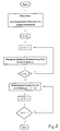
- the induced voltages were recorded at a very high speed (5000 rpm), so that disturbances due to speed fluctuations are negligible. If these measurements have to be made at lower speeds, an additional flywheel would be required. If this motor is fed with the phase current curves determined according to the flow diagram according to FIG. 2, the torque curve is very uniform without fluctuations. Any residual disturbances can be detected by a measurement and eliminated by appropriately adapted current curves in a second step or in additional subsequent steps.
- the ordinal number of the current harmonics is determined so that they interact with the largest voltage harmonics (basic harmonics).
- the disturbance torques that arise from the interaction of the calculated current harmonics with voltage components, the atomic number of which Fundamental harmonics deviate, are calculated and eliminated step by step through an iterative correction process.
- the permanent magnetic cogging torque from the torque equation (Eq. 1-15) is a function of the rotor angle ⁇ .
- T r T r ( ⁇ ); (3 -1)
- this part is independent of the current.
- the torque curve can be determined via a field calculation or directly via a measurement.
- the route via the (numerical) field calculations sometimes leads to very uncertain results.
- the effects of these effects are directly included in a torque measurement. Two methods are available for torque measurement:
- the derivation of the system of equations for the compensation of the permanent magnetic and mechanical torque component begins with the representation of the dynamic equation of motion for the measuring system according to FIG. 5.
- the drive servo motor is controlled via a controllable voltage source in such a way that the permanent magnetic tilting moments of the currentless test motor are just overcome at the lowest possible speed will.
- the torque that occurs can be measured in the steady state via the armature current of the drive motor.
- T f (I ( ⁇ )); (3 -2)
- the measurable torque consists of three components, which are considered below.
- the cogging torque T r is triggered by a superimposition of the permanent magnetic torque fluctuations, the mechanical torque fluctuations and the speed-independent friction torque component.
- T 2 ( ⁇ ) can depend linearly or strongly non-linearly on the speed. Influencing variables are bearing and brush friction, air friction, eddy current and hysteresis braking torques.
- the current curve can alternatively be determined on the basis of a harmonic analysis.
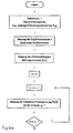
- phase current curves can be seen from the flow diagram according to FIG. 6 (with the parts of FIGS. 6a, 6b and 6c).
- the measurements on the engine required for the calculation are carried out fully automatically on a measuring and test stand, so that the engine can then be operated and tested with the determined correction curve.
- FIG. 7 shows, for a motor phase, the current curve determined in the iterative method according to the flow diagram according to FIG. 6 in a standardized form for the compensation of permanent magnetic and mechanical torque fluctuations.
- 8 and 9 show curves for the standstill torque before and after the electronic correction.
- 10 now shows an exemplary embodiment in a schematic representation of an arrangement for actuating electromechanical converters, in the present case an electric motor.
- 10 contains a motor controller 10, an arithmetic circuit unit 20, a function memory 30 and a power supply for the motor 3, which in the present example consists of a current controller 5, an output stage 6, a DC voltage supply 7 and a current measuring device 4.
- the arithmetic circuit unit contains two multipliers 21 and 22 and a logic circuit in the form of an accumulator (summer) 23, the output signal of which controls the current regulator 5.
- the function memory 30 contains two curve memories 31 and 32 in the present case, so that two different terms can be taken into account. Should other terms, e.g. B.
- the arithmetic circuit unit 20 and the functional memory 30 are still to be expanded by the corresponding elements.
- the links may not be multiplicative and additive, as shown in Fig. 10, but if necessary by corresponding other functional links.
- each of the memory sections can be divided into several parts so that different data records can be stored for each influencing variable. These different data records are then selected by an input variable 33.
- the motor controller 10 contains a torque control 11, a speed controller 12 and a position controller 13, the output signals of which are optionally applied to an input 25 of the arithmetic circuit unit 20 via a changeover switch, as well as a speed and direction of rotation detection 14.
- a changeover switch as well as a speed and direction of rotation detection 14.
- an input 24 is provided for the arithmetic circuit unit.
- the motor 3 is coupled to an angle encoder 2 in order to deliver corresponding angular position signals both for the function memory 30 and for the motor controller 10.
- Input variable 33 decides on the selection of special curves to take various operating states into account (non-linear operation due to iron saturation and armature reaction, temperature ) and motor operating modes (e.g. uniform operation or pulsating operation as stepper motor).
- the following input variables are of interest for the circuit arrangement: manipulated variables for the amplitudes of the stored nominated curves or the curve generator, possibly a signal variable which enables the curves to be read out depending on the time or depending on the rotor position, control or signal variables for selecting the curves and possibly for changing the curves Curve shape especially with non-linear motor characteristics, where the curve shape has to be adjusted according to the operating state.
- control variables for an arithmetic circuit unit 20 can also occur, for example, which control the sequence of the linking of manipulated variables and curves or change the linking function in accordance with the operating state of the engine.
- the output variables are digital, analog or other signal quantities which, if necessary, impress the motor phases via a power controller, defined currents or voltages in order to improve the concentricity of the motor or the operating characteristics in general.
- the data for curves which lead to the compensation of the individual types of torque fluctuations are stored in the function memory 30.
- the data can be saved in the form of tables, regulations (e.g. limitation of the maximum current amplitude), equations or functions.
- regulations e.g. limitation of the maximum current amplitude
- equations or functions e.g. limitation of the maximum current amplitude
- the function memory 30 can also be replaced by curve generators which generate the defined curves.
- An arithmetic circuit unit 20 now links the curve amplitudes provided as a function of time or rotor angle to the input manipulated variables according to defined functions.
- the current curve values calculated for a rotor revolution of the individual phases for reducing the electromagnetic torque fluctuation (curve memory 32) and the permanent magnetic including the mechanical fluctuation (curve memory 31) are separated and stored in standardized form.
- the current curve of the curve memory 31 is read out in accordance with the rotor angle ⁇ and multiplied by a current amplitude i A (input 24).
- the amplitude i A is chosen so that the permanent magnetic torque fluctuations are minimal.
- the amplitude i A is also contained in the stored data set. For motors with an unsaturated iron circuit and negligible armature reaction, the amplitude can be kept constant. Otherwise, the value must be updated according to the circumstances.
- the current curve generated in this way flows unchanged into the individual phase windings, regardless of the operating state of the motor and thus compensates for the permanent magnetically and mechanically caused torque pulsations.
- a third path or further paths consisting of an additional memory section and a logic element (not shown), can be added to the circuit according to FIG. 10, which the Reduction of the reluctant fluctuations allowed by appropriate current profiles.
- the electrical circuit can be implemented in various ways. For example, it can be constructed purely in terms of hardware from analog and / or digital modules, or it can also be implemented in software using a computer program.
- a torque control as well as a position, speed or acceleration control can now be superimposed on the electrical circuit.
- the overall circuit has the structure of a cascade control.
- a speed controller 12 is internally subordinate to the position controller 13 in the motor controller 10, and a current controller 5 is subordinate to this externally.
- the main difference to other position, speed, acceleration and torque controls lies in the fact that due to the selected current curve control any torque fluctuations are suppressed even in the beginning and thus the superimposed control loops are relieved very much.
- the controllers are only to be designed for a fine correction. There is no need for a controller to impress a torque.
- the proposed electronic circuit is suitable for controlling motors with any current curve. If you add an additional frequency-controllable pulse generator parallel to the angle encoder 2, this circuit is suitable for universal operation of all types of small electric motors, i.e. also for externally controlled and non-position-controlled motors, such as general synchronous motors, stepper motors, asynchronous motors etc. For the feedback Operation one switches the angle encoder 2 and for the controlled operation the pulse generator in the electrical circuit.
Landscapes
- Physics & Mathematics (AREA)
- General Physics & Mathematics (AREA)
- Control Of Electric Motors In General (AREA)
- Control Of Ac Motors In General (AREA)
Abstract
Claims (19)
- Procédé de commande de convertisseurs électromécaniques pour obtenir un profil prédéterminé de force ou de couple, notamment pour réduire les variations de couple de rotation dépendant de l'angle, dans les moteurs électriques,- selon lequel on enregistre dans une mémoire de fonction (30) des jeux de données dépendant du temps ou de la position (dépendant de la course ou de l'angle de rotation), jeux qui dépendent de la course ou de l'angle parcouru pendant le fonctionnement ou qui sont appelés de manière commandée dans le temps pour être combinés par une unité arithmétique (20) avec une grandeur d'entrée pour former les valeurs instantanées et- selon lequel, en fonction des valeurs instantanées on applique des tensions ou des intensités avec des formes de courbes correspondantes dépendant du temps ou de la position aux bornes électriques du convertisseur (3),procédé caractérisé en ce que la mémoire de fonction (30) contient plusieurs jeux de données différents obtenus à partir du profil de la force ou du couple du convertisseur (3) et le cas échéant d'une charge reliée en tenant compte de différentes influences, jeu de données notamment sous la forme de tableaux de prescriptions, d'équations ou de fonctions,- ces jeux de données sont appelés en fonction de la position ou en fonction du temps dans la mémoire de fonction (30) et sont combinés séparément selon les influences, par jeux avec chaque fois au moins une grandeur d'entrée (24, 25, 26, 27) et ces résultats de combinaisons ainsi obtenus sont réunis aux valeurs instantanées dépendant de la position ou du temps.
- Procédé selon la revendication 1 pour la commande de convertisseurs électromagnétiques (3),
caractérisé en ce que
on tient compte d'au moins deux grandeurs suivantes influençant le profil de la force ou du couple du convertisseur (3) et le cas échéant de la charge raccordée :a) influence électromagnétique,b) influence réluctante,c) influence par aimant permanent,d) influence mécanique (convertisseur et le cas échéant également charge raccordée). - Procédé de commande d'un convertisseur électromagnétique pour créer un profil prédéterminé de force ou de couple, notamment pour réduire les variations de couple dépendant de l'angle dans des moteurs électriques,- selon lequel une mémoire de fonction (30) contient des jeux de données dépendant de la position (course ou angle de rotation) et qui ont été appelés en dépendance de la course ou de l'angle de rotation parcouru pendant le fonctionnement ou commandés en fonction du temps, et qui sont combinés dans une unité arithmétique (20) d'une grandeur d'entrée pour former des valeurs instantanées et- selon lequel, en fonction des valeurs instantanées on applique des tensions ou des intensités à courbe de forme correspondante dépendant du temps ou de la position dans les bornes électriques du convertisseur (3),- procédé caractérisé en ce que dans la mémoire de fonction (30) on enregistre un jeu de données déterminé à partir du profil de la force ou du couple du convertisseur (3), et tenant compte des influences d'aimantation permanente du convertisseur, on appelle ce jeu de données dans la mémoire de fonction (30) en dépendance de la position ou du temps et on combine avec au moins une grandeur d'entrée (24, 25, 26, 27) et- les résultats obtenus des combinaisons représentent les valeurs instantanées dépendant de la position ou du temps.
- Procédé de commande de convertisseurs électromécaniques (3) pour créer un profil prédéterminé de force ou de couple, notamment pour réduire les variations de couple des moteurs électriques dépendant de l'angle,- selon lequel on enregistre dans une mémoire de fonction (30) des jeux de données dépendant de la position (dépendant de la course ou de l'angle de rotation), ces jeux étant appelés en fonction de la course ou de l'angle parcouru pendant le fonctionnement ou de manière commandée dans le temps et sont combinés à une grandeur d'entrée dans une unité arithmétique (20) pour former des valeurs instantanées, et- selon lequel, en fonction de la valeur instantanée des tensions et des intensités on applique aux bornes électriques du convertisseur (3) des tensions ou intensités avec des profils de courbe correspondants, dépendant du temps ou de la position,procédé caractérisé en ce qu'on appelle dans la mémoire de fonction, selon la position ou le temps, un jeu de données obtenu à partir du profil, de la force ou du couple du convertisseur et le cas échéant de la charge raccordée et qui tient compte des influences mécaniques et on combine ce jeu à au moins une grandeur d'entrée (24, 25, 26) et les résultats ainsi obtenus de la combinaison représentent les valeurs instantanées dépendant de la position ou du temps.
- Procédé selon l'une des revendications 1 à 4, caractérisé en ce que l'on applique non seulement des composantes d'intensité ou de tension pour la force souhaitée ou pour le couple utile mais en plus on applique des composantes d'intensité ou de tension pour compenser les forces parasites ou les couples parasites dont la direction se distingue de la direction de la force utile ou du couple utile.
- Procédé selon la revendication 5 pour un moteur électrique (3), caractérisé en ce qu'on applique les tensions ou les intensités tenant compte de ces forces ou couples parasites dans d'autres directions, au moins en partie par des enroulements supplémentaires.
- Procédé selon l'une des revendications 1 à 6, caractérisé en ce que les jeux de données tenant compte du profil, des forces ou du couple du convertisseur (3) et le cas échéant de la charge ne sont calculés qu'à partir de données de construction ou de matériaux.
- Procédé selon l'une des revendications 1 à 6, caractérisé en ce que les jeux de données tenant compte du profil, de la force ou du couple du convertisseur (3) et le cas échéant de la charge sont calculés à partir de paramètres et/ou de courbes caractéristiques mesurés sur un modèle.
- Procédé selon l'une des revendications 1 à 6, caractérisé en ce que les jeux de données tenant compte du profil, de la force ou du couple du convertisseur (3) et le cas échéant de la charge sont obtenus par des parcours de mesure pour optimiser un profil prédéterminé de force ou de couple d'un modèle dans un poste de mesures et d'essais.
- Procédé selon l'une des revendications 7, 8 ou 9 en combinaison avec la revendication 2 ou 4, caractérisé en ce qu'en plus des influences du convertisseur (3) on tient également compte des influences d'une charge couplée au convertisseur.
- Procédé selon une ou plusieurs des revendications 1 à 10, caractérisé en ce qu'au moins l'une des grandeurs d'entrée (24, 25, 26, 27) est une constante ou une grandeur adaptée aux effets pour des états de fonctionnement correspondant à une caractéristique non linéaire de convertisseur, la saturation du fer, l'excitation en retour de l'induit, etc...
- Procédé selon une ou plusieurs des revendications 1 à 10, caractérisé en ce qu'au moins l'une des grandeurs d'entrée (24, 25, 26, 27) est une grandeur guide par exemple une régulation ou commande de force, de couple, de vitesse de rotation, d'accélération et/ou de position.
- Procédé selon la revendication 11 ou 12, caractérisé en ce que les grandeurs d'entrée (24, 25, 26, 27) peuvent être commutées.
- Procédé selon une ou plusieurs des revendications précédentes, caractérisé en ce que l'on a plusieurs jeux de données par influence qui sont choisis par une autre grandeur d'entrée (26, 27) selon l'état de fonctionnement, notamment pour tenir compte d'une caractéristique non linéaire du convertisseur, de la saturation du fer, de la réaction de l'induit, etc...et/ou pour modifier le comportement en fonctionnement du convertisseur (3).
- Montage pour la mise en oeuvre du procédé selon une ou plusieurs des revendications précédentes, caractérisé par une mémoire de fonction (30) comprenant chaque fois une zone de mémoire (31, 32) pour toute influence à prendre en compte, pour enregistrer le jeu de données correspondant,- une unité arithmétique (20) pour combiner des jeux de données lues dans les zones de mémoire avec au moins une grandeur d'entrée (24, 25, 26) et pour réunir les résultats de la combinaison et former des valeurs instantanées,- un capteur de position ou de temps (2) associé au convertisseur électromécanique (3) pour commander la lecture des données dans la mémoire de fonction selon la position ou le temps et- un régulateur de puissance (6) pour appliquer des tensions ou intensités aux bornes électriques du convertisseur (3) selon les valeurs instantanées.
- Montage selon la revendication 15, caractérisé en ce que l'unité arithmétique (20) comporte des éléments multiplicateurs (21, 22) pour combiner les jeux de données lus avec chaque fois une grandeur d'entrée (24, 25, 26, 27) ainsi qu'un élément d'addition/ soustraction (23) pour réunir avec ou sans exploitation, les résultats de la multiplication.
- Montage selon la revendication 15 ou 16, pour un convertisseur (3) polyphasé,
caractérisé en ce que des jeux de données correspondants sont enregistrés pour les différentes phases et en liaison avec les grandeurs d'entrée (24, 25, 26, 27) on déduit des valeurs instantanées correspondantes et en ce que pour chacune des différentes phases on met en oeuvre des mémoires de fonction (30) correspondantes, des unités arithmétiques (20) et des régulateurs de puissance (6) ou on les fait travailler de manière multiplexée dans le temps. - Montage selon la revendication 15 ou 16 pour un convertisseur polyphasé (3),
caractérisé en ce que l'on enregistre des jeux de données communs pour toutes les phases et- pour les différentes phases on lit ces jeux de données avec déphasage et on les combine dans la ou les unités arithmétiques (20) avec les grandeurs d'entrée (24, 25, 26, 27) pour former les valeurs instantanées associées aux différentes phases. - Montage selon la revendication 15 ou 16 pour un convertisseur polyphasé (3),
caractérisé en ce que l'on enregistre des jeux de données communs pour toutes les phases et à partir de ces jeux de données on déduit des valeurs instantanées et en ce qu'il est prévu une unité de déphasage qui, à partir des valeurs instantanées communes, déduit les valeurs instantanées déphasées de l'angle de phase correspondant pour toutes les phases.
Applications Claiming Priority (11)
| Application Number | Priority Date | Filing Date | Title |
|---|---|---|---|
| CH4643/88 | 1988-12-15 | ||
| CH464488 | 1988-12-15 | ||
| CH464388 | 1988-12-15 | ||
| CH4644/88 | 1988-12-18 | ||
| CH76389 | 1989-03-02 | ||
| CH763/89 | 1989-03-02 | ||
| CH1523/89 | 1989-04-21 | ||
| CH152389 | 1989-04-21 | ||
| DE3930898 | 1989-09-15 | ||
| DE3930898 | 1989-09-15 | ||
| PCT/EP1989/001545 WO1990007229A1 (fr) | 1988-12-15 | 1989-12-15 | Procede et dispositif pour la commande de convertisseurs electro-mecaniques |
Publications (2)
| Publication Number | Publication Date |
|---|---|
| EP0448610A1 EP0448610A1 (fr) | 1991-10-02 |
| EP0448610B1 true EP0448610B1 (fr) | 1994-06-29 |
Family
ID=27508887
Family Applications (2)
| Application Number | Title | Priority Date | Filing Date |
|---|---|---|---|
| EP90900794A Expired - Lifetime EP0448610B1 (fr) | 1988-12-15 | 1989-12-15 | Procede et dispositif pour la commande de convertisseurs electro-mecaniques |
| EP89123200A Withdrawn EP0377854A1 (fr) | 1988-12-15 | 1989-12-15 | Station de mesure et d'essai pour un convertisseur électromécanique |
Family Applications After (1)
| Application Number | Title | Priority Date | Filing Date |
|---|---|---|---|
| EP89123200A Withdrawn EP0377854A1 (fr) | 1988-12-15 | 1989-12-15 | Station de mesure et d'essai pour un convertisseur électromécanique |
Country Status (4)
| Country | Link |
|---|---|
| US (1) | US5274313A (fr) |
| EP (2) | EP0448610B1 (fr) |
| DE (1) | DE58907988D1 (fr) |
| WO (1) | WO1990007229A1 (fr) |
Families Citing this family (17)
| Publication number | Priority date | Publication date | Assignee | Title |
|---|---|---|---|---|
| US5638051A (en) * | 1991-10-25 | 1997-06-10 | Siemens Aktiengesellschaft | Method and apparatus for monitoring an electrical drive |
| JP3066622B2 (ja) * | 1992-08-04 | 2000-07-17 | 本田技研工業株式会社 | 電気自動車用同期モータ制御装置 |
| DE69226532D1 (de) * | 1992-12-30 | 1998-09-10 | Ansaldo Energia Spa | Rotorwindungsschlussdetektor |
| US5485071A (en) * | 1993-08-09 | 1996-01-16 | Bi; Chao | Method and apparatus for establishing a reference current for use in operating a synchronous motor |
| JPH07170777A (ja) * | 1993-12-14 | 1995-07-04 | Fuji Electric Co Ltd | 電動機の振動抑制制御装置 |
| US5886493A (en) * | 1995-02-16 | 1999-03-23 | The Kansai Electric Power Co., Inc. | Synchronous machine excitation control device for absorbing harmonics superposed onto fundamental current |
| US5621294A (en) * | 1995-11-21 | 1997-04-15 | Universal Instruments Corporation | Apparatus and method for force compensation in a variable reluctance motor |
| JP3806985B2 (ja) * | 1996-08-21 | 2006-08-09 | 株式会社ニコン | ステッピングモータ駆動装置 |
| US5886489A (en) * | 1996-12-04 | 1999-03-23 | International Business Machines Corporation | Apparatus and method for reducing spindle power and acoustic noise in a disk drive |
| FI112891B (fi) * | 1998-09-04 | 2004-01-30 | Kone Corp | Menetelmä virtasäädetyn moottorin ohjaamiseksi |
| GB0109643D0 (en) * | 2001-04-19 | 2001-06-13 | Isis Innovation | System and method for monitoring and control |
| US6480130B1 (en) * | 2001-06-28 | 2002-11-12 | Honeywell International Inc. | Method for improving repeatability and removing hysteresis from electromechanical actuators |
| US7117754B2 (en) * | 2002-10-28 | 2006-10-10 | The Curators Of The University Of Missouri | Torque ripple sensor and mitigation mechanism |
| WO2004082482A1 (fr) * | 2003-03-20 | 2004-09-30 | Matsushita Electric Industrial Co. Ltd. | Sonde ultrasonore et dispositif ultrasonographique |
| JP2005033959A (ja) * | 2003-07-10 | 2005-02-03 | Fanuc Ltd | モータ、及びモータの制御方法 |
| DE102004001932B4 (de) * | 2004-01-14 | 2009-10-01 | Minebea Co., Ltd. | Verfahren zur Ansteuerung eines elektronisch kommutierten Motors und Motorsteuerung |
| EP2706420B1 (fr) * | 2012-09-05 | 2015-03-18 | Siemens Aktiengesellschaft | Procédé destiné au fonctionnement d'un appareil d'automatisation |
Family Cites Families (22)
| Publication number | Priority date | Publication date | Assignee | Title |
|---|---|---|---|---|
| DE1954089A1 (de) * | 1969-10-28 | 1971-05-06 | Siemens Ag | Einrichtung zum Erzeugen einer dem Drehmoment einer Induktionsmaschine proportionalen Groesse |
| US3839665A (en) * | 1970-03-30 | 1974-10-01 | A Gabor | Apparatus measuring relative velocity of movable members including means to detect velocity from the position encoder |
| DE2420166A1 (de) * | 1974-04-25 | 1975-11-13 | Siemens Ag | Winkelschrittgeber fuer eine elektrische maschine |
| DE2737372C3 (de) * | 1977-08-18 | 1980-08-14 | Max-Planck-Gesellschaft Zur Foerderung Der Wissenschaften E.V., 3400 Goettingen | Einrichtung zum Erzeugen einer periodisch hin- und hergehenden geradlinigen Bewegung eines Bauteiles mit einer im wesentlichen konstanten Geschwindigkeit |
| US4228396A (en) * | 1978-05-26 | 1980-10-14 | Dataproducts Corporation | Electronic tachometer and combined brushless motor commutation and tachometer system |
| DE2834740A1 (de) * | 1978-08-08 | 1980-02-21 | Franz Vertriebs Gmbh | Antriebsanordnung fuer ein informationsspeicherlaufwerk insbesondere fuer einen plattenspieler |
| US4205383A (en) * | 1978-11-13 | 1980-05-27 | Bakanovich Eduard A | Method of testing objects for random actions thereon and digital simulator-computer system for effecting same |
| IT1165014B (it) * | 1979-03-27 | 1987-04-22 | Innocenti Santeustacchio Spa | Sistema di controllo geometrico,per aumentare la precisione du una macchina utensile,particolarmente di una macchina utensile di grandi dimensioni |
| US4270074A (en) * | 1979-10-22 | 1981-05-26 | The Singer Company | Brushless DC motor control utilizing a ROM |
| US4429262A (en) * | 1980-09-12 | 1984-01-31 | Technicare Corporation | Three phase motor oscillatory servo control |
| US4447771A (en) * | 1981-08-31 | 1984-05-08 | Kollmorgen Technologies Corporation | Control system for synchronous brushless motors |
| US4559485A (en) * | 1981-08-31 | 1985-12-17 | Kollmorgen Technologies Corporation | Control systems for AC induction motors |
| JPS59123482A (ja) * | 1982-12-29 | 1984-07-17 | Fanuc Ltd | 同期モータの制御装置 |
| EP0180083B1 (fr) * | 1984-10-19 | 1990-08-22 | Kollmorgen Corporation | Systèmes de régulation pour machines à réluctance variable |
| JPH0667258B2 (ja) * | 1985-08-12 | 1994-08-24 | 松下電器産業株式会社 | ブラシレスモ−タ |
| JPS63314195A (ja) * | 1987-01-30 | 1988-12-22 | Nippon Digital Equip Kenkyu Kaihatsu Center Kk | 三相直流ブラシレスモ−タの駆動方法および装置 |
| US4841184A (en) * | 1987-06-23 | 1989-06-20 | Mechanical Technology Incorporated | Velocity and imbalance observer control circuit for active magnetic bearing or damper |
| US4814677A (en) * | 1987-12-14 | 1989-03-21 | General Electric Company | Field orientation control of a permanent magnet motor |
| US4884016A (en) * | 1988-08-23 | 1989-11-28 | Aerotech, Inc. | Closed loop torque angle control of synchronous motor |
| JPH0295192A (ja) * | 1988-09-29 | 1990-04-05 | Sony Corp | ホールモータの回転制御回路 |
| US5023528A (en) * | 1988-10-27 | 1991-06-11 | Advanced Engineering Systems, Operation & Products, Inc. | Method of three-phase winding motor control of rotary motor-driven linear actuators, linear motor-actuated carriages, and similar systems, and apparatus for practicing the same |
| US4999534A (en) * | 1990-01-19 | 1991-03-12 | Contraves Goerz Corporation | Active vibration reduction in apparatus with cross-coupling between control axes |
-
1989
- 1989-12-15 EP EP90900794A patent/EP0448610B1/fr not_active Expired - Lifetime
- 1989-12-15 WO PCT/EP1989/001545 patent/WO1990007229A1/fr active IP Right Grant
- 1989-12-15 EP EP89123200A patent/EP0377854A1/fr not_active Withdrawn
- 1989-12-15 DE DE58907988T patent/DE58907988D1/de not_active Expired - Fee Related
- 1989-12-15 US US07/681,511 patent/US5274313A/en not_active Expired - Fee Related
Also Published As
| Publication number | Publication date |
|---|---|
| WO1990007229A1 (fr) | 1990-06-28 |
| US5274313A (en) | 1993-12-28 |
| EP0377854A1 (fr) | 1990-07-18 |
| EP0448610A1 (fr) | 1991-10-02 |
| DE58907988D1 (de) | 1994-08-04 |
Similar Documents
| Publication | Publication Date | Title |
|---|---|---|
| EP0448610B1 (fr) | Procede et dispositif pour la commande de convertisseurs electro-mecaniques | |
| EP0151296B1 (fr) | Circuit de commande pour un moteur pas à pas | |
| DE3941553A1 (de) | Verfahren und anordnung zur ansteuerung elektromechanischer wandler | |
| DE69731578T2 (de) | Steuerungsgerät für einen bürstenlosen Motor und Gerät zum Feststellen der Ankerstellung eines solchen Motors | |
| DE60029548T2 (de) | Regelung für eine bürstenlose Maschine | |
| DE2341761C3 (de) | Schaltungsanordnung zum Betrieb eines fahrweggebundenen Triebfahrzeuges mit einem synchronen Linearmotor | |
| DE4437793C2 (de) | Verfahren und Vorrichtung zur Steuerung eines Elektromotors | |
| DE69930114T2 (de) | Motorregelvorrichtung | |
| DE69818585T2 (de) | Verfahren zum Regeln von Drehmomentschwankungen eines Motors mit Permanentmagneten im Inneren und ein Regler mit diesem Verfahren | |
| DE112009001282B4 (de) | Drehwinkelerfassungsvorrichtung | |
| DE3504681C2 (fr) | ||
| EP3134964B1 (fr) | Procede et dispositif pour reduire l'ondulation de couple dans un moteur a courant continu | |
| EP0762625A1 (fr) | Entraînement électrique | |
| DE2758423A1 (de) | Elektrischer antrieb | |
| DE2803839C2 (fr) | ||
| WO2020064420A1 (fr) | Réduction de bruits parasites et/ou de vibrations lors du fonctionnement d'une machine électrique | |
| DE2612721B2 (de) | Schaltungsanordnung zur Regelung der Drehzahl und der Winkellage des Läufers eines Gleichstrommotors | |
| EP0690556B1 (fr) | Reconnaissance de l'arrêt d'un moteur tournant alimenté par un onduleur sans capteur de vitesse, dans le cas d'un redémarrage | |
| DE60036679T2 (de) | Regelung für eine geschaltete Reluktanzmaschine | |
| DE3740712A1 (de) | Beschleunigunssteuervorrichtung | |
| DE19503492A1 (de) | Vorrichtung zum Antrieb und Lagebestimmung bei einem Stellsystem | |
| DE2914495A1 (de) | Kreisellaeuferantrieb | |
| EP0469177A1 (fr) | Procédé et dispositif pour le redémarrage d'un moteur à induction | |
| DE60038648T2 (de) | Regelungsprozess für eine drehende Maschine und Vorrichtung zur Versorgung dieser Maschine | |
| EP1127278B1 (fr) | Dispositif et procede pour la production d'un signal partiellement synthetise de haute qualite dynamique correspondant a l'acceleration d'un rotor dans un dispositif d'entrainement electrique |
Legal Events
| Date | Code | Title | Description |
|---|---|---|---|
| PUAI | Public reference made under article 153(3) epc to a published international application that has entered the european phase |
Free format text: ORIGINAL CODE: 0009012 |
|
| 17P | Request for examination filed |
Effective date: 19910601 |
|
| AK | Designated contracting states |
Kind code of ref document: A1 Designated state(s): CH DE FR GB IT LI NL SE |
|
| 17Q | First examination report despatched |
Effective date: 19920615 |
|
| RBV | Designated contracting states (corrected) |
Designated state(s): DE GB IT |
|
| GRAA | (expected) grant |
Free format text: ORIGINAL CODE: 0009210 |
|
| AK | Designated contracting states |
Kind code of ref document: B1 Designated state(s): DE GB IT |
|
| ITF | It: translation for a ep patent filed |
Owner name: FIAMMENGHI FIAMMENGHI RACHELI |
|
| REF | Corresponds to: |
Ref document number: 58907988 Country of ref document: DE Date of ref document: 19940804 |
|
| GBT | Gb: translation of ep patent filed (gb section 77(6)(a)/1977) |
Effective date: 19940802 |
|
| RAP2 | Party data changed (patent owner data changed or rights of a patent transferred) |
Owner name: PAPST LICENSING GMBH |
|
| ITTA | It: last paid annual fee | ||
| REG | Reference to a national code |
Ref country code: GB Ref legal event code: 732E |
|
| PLBE | No opposition filed within time limit |
Free format text: ORIGINAL CODE: 0009261 |
|
| STAA | Information on the status of an ep patent application or granted ep patent |
Free format text: STATUS: NO OPPOSITION FILED WITHIN TIME LIMIT |
|
| 26N | No opposition filed | ||
| REG | Reference to a national code |
Ref country code: GB Ref legal event code: IF02 |
|
| PGFP | Annual fee paid to national office [announced via postgrant information from national office to epo] |
Ref country code: GB Payment date: 20041203 Year of fee payment: 16 |
|
| PGFP | Annual fee paid to national office [announced via postgrant information from national office to epo] |
Ref country code: DE Payment date: 20050125 Year of fee payment: 16 |
|
| PG25 | Lapsed in a contracting state [announced via postgrant information from national office to epo] |
Ref country code: IT Free format text: LAPSE BECAUSE OF NON-PAYMENT OF DUE FEES;WARNING: LAPSES OF ITALIAN PATENTS WITH EFFECTIVE DATE BEFORE 2007 MAY HAVE OCCURRED AT ANY TIME BEFORE 2007. THE CORRECT EFFECTIVE DATE MAY BE DIFFERENT FROM THE ONE RECORDED. Effective date: 20051215 Ref country code: GB Free format text: LAPSE BECAUSE OF NON-PAYMENT OF DUE FEES Effective date: 20051215 |
|
| PG25 | Lapsed in a contracting state [announced via postgrant information from national office to epo] |
Ref country code: DE Free format text: LAPSE BECAUSE OF NON-PAYMENT OF DUE FEES Effective date: 20060701 |
|
| GBPC | Gb: european patent ceased through non-payment of renewal fee |
Effective date: 20051215 |