EP0447863A1 - Train de roues pour des conteneurs, engins, etc. - Google Patents
Train de roues pour des conteneurs, engins, etc. Download PDFInfo
- Publication number
- EP0447863A1 EP0447863A1 EP91103168A EP91103168A EP0447863A1 EP 0447863 A1 EP0447863 A1 EP 0447863A1 EP 91103168 A EP91103168 A EP 91103168A EP 91103168 A EP91103168 A EP 91103168A EP 0447863 A1 EP0447863 A1 EP 0447863A1
- Authority
- EP
- European Patent Office
- Prior art keywords
- lever
- bearing
- roller
- rocker
- push rod
- Prior art date
- Legal status (The legal status is an assumption and is not a legal conclusion. Google has not performed a legal analysis and makes no representation as to the accuracy of the status listed.)
- Withdrawn
Links
Images


Classifications
-
- B—PERFORMING OPERATIONS; TRANSPORTING
- B62—LAND VEHICLES FOR TRAVELLING OTHERWISE THAN ON RAILS
- B62B—HAND-PROPELLED VEHICLES, e.g. HAND CARTS OR PERAMBULATORS; SLEDGES
- B62B5/00—Accessories or details specially adapted for hand carts
- B62B5/04—Braking mechanisms; Locking devices against movement
- B62B5/0457—Braking mechanisms; Locking devices against movement by locking in a braking position
- B62B5/0461—Braking mechanisms; Locking devices against movement by locking in a braking position with positive engagement
Definitions
- the invention relates to a chassis for transport containers, apparatus or the like.
- a base plate and - mounted thereon at least two rollers and a locking device for a blocking device for at least the rotational movement of the wheels of the rollers
- the locking device each having at least one locking lever and one Has release levers which are coupled to one another via a linkage arrangement and are operatively connected to tappet-side tappets as part of the blocking device, whereby on a rocker arm pivotably mounted on the base plate, on the one hand, handlebars connected to the levers, and on the other hand, push rods engage with which at least indirectly wedge surfaces for adjusting the tappets are connected are.
- this is intended for a landing gear for serving trolleys that serve as mobile containers in commercial aircraft for storing food and beverages that are issued to the passengers, and then for collecting the empty containers and packaging.
- Such transport containers are called “trolleys”.
- An undercarriage for trolleys has become known through obvious prior use, which is very complicated in the construction of its locking device and blocking device.
- the present invention is based on such a chassis.
- the push rods which are in turn articulated on the rocker, are coupled with adjustable brackets mounted in brackets.
- These adjusting brackets which like their bearings consist of complex light-alloy die-cast parts, act on stroke-adjusting rods in the bearing cheeks of the bearings with respect to the height.
- the object of the invention is therefore to provide a chassis of the type outlined in the preamble of claim 1, which is considerably simplified in its construction and in which the blocking device always acts reliably for each roller to be blocked.
- the design of the undercarriage should also allow a simple arrangement of a swivel lock of the castors if necessary.
- the invention solves this problem primarily and essentially in that the push rods directly are guided from the rocker to the rollers and are provided with the wedge surfaces that are supported on the tappets by pressure.
- the push rods are guided directly, that is to say in short ways, directly from the rocker to the respective roller.
- the wedge surfaces previously located on the rotating bodies are now arranged on the push rods and serve for the direct direct action on the tappets as the components of the blocking device for at least one wheel of at least one steering roller of the undercarriage. In general, however, at least one wheel of each of a total of four castors located on the chassis is blocked.
- each push rod generally has a wedge surface that adjusts the ram. Because there are only a few interconnected parts, there is less overall play and consequently a more precise and low-wear adjustment mechanism. Of course, this also results in a considerably simplified and quicker installation of the entire undercarriage.
- each push rod each pointing from the rocker to a roller, preferably rest in a pivot bearing, which is preferably on a plate-like one Console is designed for the mounting plate of a roller.
- the end of each push rod pointing from the rocker to a roller can be overlapped by the mounting plate of the associated roller, whereby the connecting rod is held captive with respect to the base plate.
- At least one of the push rods carries an inhibiting shoe which blocks the pivoting movement of the associated roller and which presses against the roller support part when the tappet is depressed. Since the push rod is not adjusted transversely to the floor, but parallel to the floor in accordance with the invention, a restraint shoe which is fastened to the push rod and can therefore also be adjusted parallel to the floor can be arranged without further ado, so that both the wheel brake and the swivel lock on the castor take effect simultaneously can. This does not require any significant additional design effort.
- Each push rod is preferably made of plastic, and the wedge surface is integrally formed on it.
- the handlebars have web-like drivers on which the levers are each supported with claw-like actuation projections in a push-fit or pull-fit manner.
- the handlebars were previously coupled to the respective lever by means of a cotter-pin connection. It is particularly simple if the drivers on the handlebars and the actuating projections on the levers are each made of the same material and in one piece.
- the common bearing axis for the set lever and the release lever is provided with at least two axially spaced jacket projections, of which the axially outer non-rotatably in a keyhole-like notch one of the axle bearing cheeks of a lever bearing bracket and the axially inside one of the two levers is axially supported in a stepped bore, the axle bearings of the two levers being sleeve-shaped and complementing each other in their overall length to a dimension that, taking into account the required swivel movement play on the bearing axis, the clear internal dimension between the axle bearing cheeks of the levers - Storage console corresponds.
- levers and their storage are in addition to the levers themselves and the lever bracket required anyway only this specially designed bearing axis is required.
- Distance bushings and sleeves as well as washers and split pins to secure the bearing axis on the lever bearing bracket, as they were previously required, are no longer required.
- the levers are assembled without tools or external means by simply bayonet-like insertion of the bearing axis into the bearing cheeks of the lever-bearing bracket and insertion through a similar keyhole in a bearing area of one of the two levers.
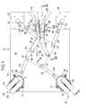
- a base plate of a transport container which can be rolled with the aid of a chassis designated as a whole by 11 is designated by 10.
- the undercarriage 11 comprises four twin casters 12 designed as swivel castors, of which a pair is shown in FIGS. 1 and 2. They are each screwed onto a plate-like console 15 by means of a mounting plate 13 and screws 14, which in turn is fastened to the base plate 10.
- a plate-like rocker arm 16 is pivotably arranged in a plane parallel to the base by means of an axis 17.
- two link levers - hereinafter referred to as links 18 and 19 - are coupled to it.
- Each link 18, 19 has a key-like extension 20 which fits into a keyhole-like recess 21 of the rocker 16. After insertion, each link 18, 19 is pivoted into the intended position shown in FIGS. 1 and 2, in which it is captively attached to the rocker by means of a locking bar-like grip.
- the handlebar 18 is coupled to a lever 22 in a plane parallel to the floor and, analogously, the handlebar 19 is coupled to a lever 23 arranged next to it.
- the lever 23 is the locking lever
- the lever 22 is the release lever for the blocking device for the wheels 24, 25 of the rollers 12 described in detail below.
- the two levers 22 and 23 are pivotally mounted in a top view U-shaped lever bearing bracket 26 on a bearing axis 27 which is screwed to the base plate 10 by means of screws 28. Besides the screws 14 and the bearing screw 17 for the rocker 16, these are the only ones of the entire undercarriage.
- each push rod 29 corresponding to the number of rollers 12 are articulated in a radially more external arrangement than that of the links 18 and 19.
- the free ends of each push rod 29 pointing away from the rocker 16 are pivotally mounted in pivot bearings 30 of the brackets 15.
- the pivot bearings 30 are formed in the brackets 15 as pockets open towards the axis 17.
- Each push rod 29 extends outward from the rocker 16 substantially in the direction of the pivot axis S of each of the four steering rollers 12.
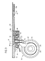
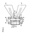
- each push rod 29 has a wedge surface 31, which points downward from the base plate 10 to the respective roller 12 and pressurizes a plunger 32, which centrally in the castor bearing 33 is vertically adjustable.
- Each tappet 32 is in motion-coupled connection via an arm 34 to a wheel brake body 35, the external toothing 36 of which is intended for engagement in a counter toothing 37 on a wheel 25. In the event of braking intervention (FIG. 3), this wheel 25 is thus locked in rotation.
- This wheel braking or locking device is also the subject of DE-GM 88 10 731 by the applicant, to which reference is made with regard to structural details.
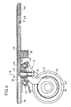
- each tappet 32 contacts the associated push rod 29 in a pressure-locking manner in the region of its wedge surface 31 or a runner thereof (FIG. 4), the tappet 32 is in an upper position which corresponds to the wheel position not braked. If the rocker arm 16 is now rotated counterclockwise in the direction of the arrow 38 by actuating the locking lever 23, starting from FIGS. 1 and 4, all four push rods 29 are advanced. Their respective wedge surface 31 pushes onto the tappet 32 and presses it downward into the braking position corresponding to FIGS. 2 and 3.
- each push rod 29 there is also an inhibiting shoe 39, which consists of an entropy-elastic material, in particular rubber or rubber-elastic plastic, and which, in the braking position, presses against the back bearing 40 of the associated roller 12, which is thereby prevented from pivoting about its pivot axis S, which coincides with the longitudinal axis of the plunger 32.
- the brake is designed on the one hand as a rotary block for at least one wheel 25 and at the same time as a swivel block for each swivel castor 12.
- each push rod 29 consisting of a molded plastic part is held directly on the surface of the base plate 10 and is held captively in place by the push rod being overlapped by the mounting plate 13 of the associated steering roller 12.
- the push rod 29 is always on the upper end face of the plunger 32. The coupling of each end of the push rod 29 facing away from the castors 12 with the rocker 16 is simply achieved by the rocker 16 engaging with a dome recess 41 over a corresponding circular coupling pin 42 at the end of the push rod 29.
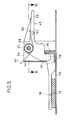
- each link 18 and 19 pass through a window 43 of the central web 44 of the lever bearing bracket 26 on their way from the rocker 16 to the respectively associated lever 22 or 23.
- each link has a web - or rib-like driver 45, with which the lever 22 cooperates in a one-sided manner by means of an extension 46 and the lever 23 by means of two extensions 47, 48, which form a claw, in a manner which is interlocking and pressure-locking.
- the arrangement is such that each lever 22, 23 on the associated one Handlebar 18 or 19 pulls when he is stepped on.
- the direction of kick for the lever 22 is designated by 49 and that for the lever 23 by 50.
- Both the two links 18 and 19 and the two levers 22 and 23 are each in turn one-piece plastic injection molded parts.
- each of the two nebulae 22 and 23 is seated on the bearing axis 27 by means of sleeve-like axle bearings 51 and 52, respectively.
- This has axially spaced and paired projections 53 and 54. These are essentially in the form of ribs tangential compression of the material of the axis 27 is formed.
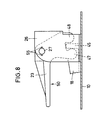
- the axially outer jacket projections 53 engage in the manner of key beards in adapted keyhole-shaped gaps 55 (FIG. 8) of one of the two axle bearing cheeks 56 of the lever bearing bracket 26.
- the other pair of projections 54 sits in a circular receptacle 57 which is formed within the bearing sleeve 52 of the lever 23.
- the bearing axis 27 is rotatably held by the positive engagement of the jacket projections 53 in the axle bearing cheek 56, while the lever 23 can pivot relative to the fixed axis 27. So that the bearing axis and lever 23 can be plugged together, the bearing bore of the mist 23 also has matching “keyholes” 63 (FIG. 7) in an arrangement that is offset circumferentially from the operating position.
- the two sleeve-shaped bearing sections 51 and 52 of the two levers 22 and 23 directly adjoin one another and have an overall length which is essentially corresponds to the clear inner width between the two legs 56 and 58 of the bracket 26.
- a leg return spring 59 is mounted on a sleeve section 51a of the lever 22, one leg 60 of which is supported in a press-fit manner under an extension 62 of the mist 22 and the other leg 61 of which rests under spring pressure on the mist bearing bracket 26 (FIG. 5).
- the locking lever 23 is depressed (arrow 50) swivels - as stated - the rocker 16 in the circumferential direction 38 and pushes the push rods 29 into the blocking position.
- the handlebar 18 is simultaneously pulled away from its associated fog 22 in the direction of the center of the plate.
- the release lever 22 is conveyed into the end position shown in FIG. 5.
- this lever 22 is depressed (arrow 49), by means of which the extension 18 pulls the handlebar 18 to the edge of the base plate 10.
- the release lever according to FIG. 5 jumps back into its favorable starting position for later actuation.
- the other handlebar 19 is pulled towards the middle of the plate. This has the consequence that the locking lever 50 is conveyed back from its position corresponding to the blocking position according to FIG. 7 into the position shown in FIG. 8, in which it can be actuated again by stepping in the direction of the arrow 50.
- each push rod 29 forms a toggle lever arrangement with the rocker 16, one toggle lever being formed by the push rod 29 itself, the other toggle lever by the connection between the pivot pins 17 and 42 and the knee coincides with the pivot pin 42.
- the blocking position according to FIG. 2 is distinguished with respect to the four toggle lever arrangements by their slight over-center position, so that the braking or blocking position is automatically secured.
- Another advantage of the toggle arrangement consists in the low actuating force of the locking lever 23 that has to be applied.
- the toggle lever blocking by depressing the release lever 22 is also easily possible with little effort.
- the blocking shoes 39 designed as elastic cushions also act to compensate for tolerances and hold the toggle lever arrangement under non-positive tension.
Landscapes
- Engineering & Computer Science (AREA)
- Chemical & Material Sciences (AREA)
- Combustion & Propulsion (AREA)
- Transportation (AREA)
- Mechanical Engineering (AREA)
- Braking Arrangements (AREA)
- Handcart (AREA)
Applications Claiming Priority (2)
| Application Number | Priority Date | Filing Date | Title |
|---|---|---|---|
| DE19904008855 DE4008855A1 (de) | 1990-03-20 | 1990-03-20 | Fahrwerk fuer transportbehaelter, apparate o. dgl. |
| DE4008855 | 1990-03-20 |
Publications (1)
| Publication Number | Publication Date |
|---|---|
| EP0447863A1 true EP0447863A1 (fr) | 1991-09-25 |
Family
ID=6402599
Family Applications (1)
| Application Number | Title | Priority Date | Filing Date |
|---|---|---|---|
| EP91103168A Withdrawn EP0447863A1 (fr) | 1990-03-20 | 1991-03-02 | Train de roues pour des conteneurs, engins, etc. |
Country Status (2)
| Country | Link |
|---|---|
| EP (1) | EP0447863A1 (fr) |
| DE (1) | DE4008855A1 (fr) |
Cited By (4)
| Publication number | Priority date | Publication date | Assignee | Title |
|---|---|---|---|---|
| EP0678438A1 (fr) * | 1994-04-21 | 1995-10-25 | Bucher Management AG | Frein pour conteneurs roulants |
| NL1006682C2 (nl) * | 1997-07-29 | 1999-02-08 | Driessen Aircraft Holding B V | Onderstel voor een wagen met name voor een trolley, alsmede een wagen voorzien van een dergelijk onderstel. |
| DE202016103782U1 (de) | 2016-07-13 | 2016-10-19 | Steinco Paul Vom Stein Gmbh | Vorrichtung zur zumindest teilweise gleichzeitigen Bremsung und/oder Feststellung einer Mehrzahl an einer Unterseite eines Gerätewagens angeordneter Rollen |
| DE102016112884B3 (de) * | 2016-07-13 | 2017-08-24 | Steinco Paul Vom Stein Gmbh | Vorrichtung zur zumindest teilweise gleichzeitigen Bremsung und/oder Feststellung einer Mehrzahl an einer Unterseite eines Gerätewagens angeordneter Rollen |
Families Citing this family (3)
| Publication number | Priority date | Publication date | Assignee | Title |
|---|---|---|---|---|
| DE202005008098U1 (de) * | 2005-05-19 | 2006-09-28 | Wanzl Metallwarenfabrik Gmbh | Transportwagen |
| DE102012100855A1 (de) * | 2012-02-02 | 2013-08-08 | Sunny Castors Co., Ltd. | Bremsrolle |
| DE102012100853A1 (de) * | 2012-02-02 | 2013-08-08 | Sunny Castors Co., Ltd. | Bremsrolle |
Citations (5)
| Publication number | Priority date | Publication date | Assignee | Title |
|---|---|---|---|---|
| GB1338643A (en) * | 1971-02-08 | 1973-11-28 | Tomado Nv | Sub-frame provided with castors |
| FR2200123A1 (fr) * | 1972-09-22 | 1974-04-19 | Walle Albert Van De | |
| DE8324703U1 (de) * | 1983-08-27 | 1984-01-12 | Rolf Rodehau GmbH & Co KG Metallwarenfabrik, 6070 Langen | Blockierbremse für rollbare Behälter, insbesondere Servierwagen in Verkehrsflugzeugen |
| GB2130316A (en) * | 1982-11-17 | 1984-05-31 | Haseltine H L | Goods trolley |
| DE8809849U1 (fr) * | 1988-08-02 | 1988-09-22 | Lermer Gmbh, 6200 Wiesbaden, De |
Family Cites Families (3)
| Publication number | Priority date | Publication date | Assignee | Title |
|---|---|---|---|---|
| GB1223039A (en) * | 1968-12-20 | 1971-02-17 | Ici Ltd | Process for the manufacture of methylene bridged polyarylamines |
| DE3431073A1 (de) * | 1983-08-27 | 1985-03-21 | Rolf Rodehau GmbH & Co KG Metallwarenfabrik, 6070 Langen | Blockierbremse fuer rollbare behaelter, insbesondere servierwagen in verkehrsflugzeugen |
| DE8810731U1 (fr) * | 1988-08-25 | 1988-10-13 | Paul Vom Stein & Co, 5632 Wermelskirchen, De |
-
1990
- 1990-03-20 DE DE19904008855 patent/DE4008855A1/de not_active Withdrawn
-
1991
- 1991-03-02 EP EP91103168A patent/EP0447863A1/fr not_active Withdrawn
Patent Citations (5)
| Publication number | Priority date | Publication date | Assignee | Title |
|---|---|---|---|---|
| GB1338643A (en) * | 1971-02-08 | 1973-11-28 | Tomado Nv | Sub-frame provided with castors |
| FR2200123A1 (fr) * | 1972-09-22 | 1974-04-19 | Walle Albert Van De | |
| GB2130316A (en) * | 1982-11-17 | 1984-05-31 | Haseltine H L | Goods trolley |
| DE8324703U1 (de) * | 1983-08-27 | 1984-01-12 | Rolf Rodehau GmbH & Co KG Metallwarenfabrik, 6070 Langen | Blockierbremse für rollbare Behälter, insbesondere Servierwagen in Verkehrsflugzeugen |
| DE8809849U1 (fr) * | 1988-08-02 | 1988-09-22 | Lermer Gmbh, 6200 Wiesbaden, De |
Cited By (6)
| Publication number | Priority date | Publication date | Assignee | Title |
|---|---|---|---|---|
| EP0678438A1 (fr) * | 1994-04-21 | 1995-10-25 | Bucher Management AG | Frein pour conteneurs roulants |
| US5634532A (en) * | 1994-04-21 | 1997-06-03 | Bucher Management Ag | Brake system for traveling container |
| NL1006682C2 (nl) * | 1997-07-29 | 1999-02-08 | Driessen Aircraft Holding B V | Onderstel voor een wagen met name voor een trolley, alsmede een wagen voorzien van een dergelijk onderstel. |
| WO1999006260A1 (fr) * | 1997-07-29 | 1999-02-11 | Driessen Aircraft Holding B.V. | Chassis pour un chariot, en particulier un chariot de service, et chariot dote dudit chassis |
| DE202016103782U1 (de) | 2016-07-13 | 2016-10-19 | Steinco Paul Vom Stein Gmbh | Vorrichtung zur zumindest teilweise gleichzeitigen Bremsung und/oder Feststellung einer Mehrzahl an einer Unterseite eines Gerätewagens angeordneter Rollen |
| DE102016112884B3 (de) * | 2016-07-13 | 2017-08-24 | Steinco Paul Vom Stein Gmbh | Vorrichtung zur zumindest teilweise gleichzeitigen Bremsung und/oder Feststellung einer Mehrzahl an einer Unterseite eines Gerätewagens angeordneter Rollen |
Also Published As
| Publication number | Publication date |
|---|---|
| DE4008855A1 (de) | 1991-09-26 |
Similar Documents
| Publication | Publication Date | Title |
|---|---|---|
| EP0678438B1 (fr) | Frein pour conteneurs roulants | |
| EP0072491B1 (fr) | Dispositif de freinage pour conteneurs roulants | |
| EP0447863A1 (fr) | Train de roues pour des conteneurs, engins, etc. | |
| CH642306A5 (de) | Lenkrolle mit bremsvorrichtung. | |
| DE19836454C2 (de) | Bremsbare Lenkrolle für Apparate, Geräte, Möbel oder dergleichen | |
| DE2841869A1 (de) | Fersenhalter fuer ausloeseskibindung | |
| DE4201012C2 (de) | Deichselgelenktes Flurförderzeug, insbesondere Gabelhubwagen | |
| DE4221541C2 (de) | Gebremste Lenkrolle | |
| DE2722230A1 (de) | Feststellvorrichtung fuer laufraeder | |
| DE3019256C2 (fr) | ||
| DE202010012390U1 (de) | Bremsvorrichtung für einen Transportwagen | |
| DE19827068C1 (de) | Längsverstellvorrichtung an einem Kraftfahrzeugsitz für insbesondere zweitürige Kraftfahrzeuge | |
| DE4025157A1 (de) | Hydraulische brems- und lenkbremseinrichtung | |
| EP0332876B1 (fr) | Chariot | |
| DE19525275C2 (de) | Bremsvorrichtung für Rollstühle | |
| DE102021126854A1 (de) | Rollwagen | |
| DE3243211A1 (de) | Lenkrolle mit einer feststellvorrichtung zum blockieren der dreh- und schwenkbeweglichkeit des laufrades | |
| DE3245422C2 (fr) | ||
| AT331645B (de) | Bremsvorrichtung fur die rader von gepacktransportkarren | |
| DE19726311C2 (de) | Reisekoffer | |
| DE2821157A1 (de) | Feststellvorrichtung an einer lenkrolle | |
| DE202004010097U1 (de) | Handbetriebenes Flurförderfahrzeug mit automatischer Feststellbremse | |
| DE202021104420U1 (de) | Laufrolleneinrichtung für mobile Behälter | |
| DE1605466C3 (de) | Lenkrolle mit Feststellhebel zum Blockieren der Schwenk- und Drehbeweglichkeit ihres Laufrades | |
| DE2336691A1 (de) | Handbewegtes flurfoerderzeug |
Legal Events
| Date | Code | Title | Description |
|---|---|---|---|
| PUAI | Public reference made under article 153(3) epc to a published international application that has entered the european phase |
Free format text: ORIGINAL CODE: 0009012 |
|
| AK | Designated contracting states |
Kind code of ref document: A1 Designated state(s): DE FR GB IT NL |
|
| 17P | Request for examination filed |
Effective date: 19920311 |
|
| 17Q | First examination report despatched |
Effective date: 19920716 |
|
| STAA | Information on the status of an ep patent application or granted ep patent |
Free format text: STATUS: THE APPLICATION HAS BEEN WITHDRAWN |
|
| 18W | Application withdrawn |
Withdrawal date: 19930311 |