EP0446776B1 - Joint d'étanchéité profilé - Google Patents
Joint d'étanchéité profilé Download PDFInfo
- Publication number
- EP0446776B1 EP0446776B1 EP91103436A EP91103436A EP0446776B1 EP 0446776 B1 EP0446776 B1 EP 0446776B1 EP 91103436 A EP91103436 A EP 91103436A EP 91103436 A EP91103436 A EP 91103436A EP 0446776 B1 EP0446776 B1 EP 0446776B1
- Authority
- EP
- European Patent Office
- Prior art keywords
- sealing
- sealing profile
- profile
- cavity
- area
- Prior art date
- Legal status (The legal status is an assumption and is not a legal conclusion. Google has not performed a legal analysis and makes no representation as to the accuracy of the status listed.)
- Expired - Lifetime
Links
Images


Classifications
-
- E—FIXED CONSTRUCTIONS
- E06—DOORS, WINDOWS, SHUTTERS, OR ROLLER BLINDS IN GENERAL; LADDERS
- E06B—FIXED OR MOVABLE CLOSURES FOR OPENINGS IN BUILDINGS, VEHICLES, FENCES OR LIKE ENCLOSURES IN GENERAL, e.g. DOORS, WINDOWS, BLINDS, GATES
- E06B7/00—Special arrangements or measures in connection with doors or windows
- E06B7/16—Sealing arrangements on wings or parts co-operating with the wings
- E06B7/22—Sealing arrangements on wings or parts co-operating with the wings by means of elastic edgings, e.g. elastic rubber tubes; by means of resilient edgings, e.g. felt or plush strips, resilient metal strips
- E06B7/23—Plastic, sponge rubber, or like strips or tubes
- E06B7/2305—Plastic, sponge rubber, or like strips or tubes with an integrally formed part for fixing the edging
-
- E—FIXED CONSTRUCTIONS
- E06—DOORS, WINDOWS, SHUTTERS, OR ROLLER BLINDS IN GENERAL; LADDERS
- E06B—FIXED OR MOVABLE CLOSURES FOR OPENINGS IN BUILDINGS, VEHICLES, FENCES OR LIKE ENCLOSURES IN GENERAL, e.g. DOORS, WINDOWS, BLINDS, GATES
- E06B3/00—Window sashes, door leaves, or like elements for closing wall or like openings; Layout of fixed or moving closures, e.g. windows in wall or like openings; Features of rigidly-mounted outer frames relating to the mounting of wing frames
- E06B3/54—Fixing of glass panes or like plates
- E06B3/58—Fixing of glass panes or like plates by means of borders, cleats, or the like
- E06B3/62—Fixing of glass panes or like plates by means of borders, cleats, or the like of rubber-like elastic cleats
-
- E—FIXED CONSTRUCTIONS
- E06—DOORS, WINDOWS, SHUTTERS, OR ROLLER BLINDS IN GENERAL; LADDERS
- E06B—FIXED OR MOVABLE CLOSURES FOR OPENINGS IN BUILDINGS, VEHICLES, FENCES OR LIKE ENCLOSURES IN GENERAL, e.g. DOORS, WINDOWS, BLINDS, GATES
- E06B7/00—Special arrangements or measures in connection with doors or windows
- E06B7/16—Sealing arrangements on wings or parts co-operating with the wings
- E06B7/22—Sealing arrangements on wings or parts co-operating with the wings by means of elastic edgings, e.g. elastic rubber tubes; by means of resilient edgings, e.g. felt or plush strips, resilient metal strips
- E06B7/23—Plastic, sponge rubber, or like strips or tubes
- E06B7/2301—Plastic, sponge rubber, or like strips or tubes without an integrally formed part for fixing the edging
- E06B7/2303—Plastic, sponge rubber, or like strips or tubes without an integrally formed part for fixing the edging hollow
-
- E—FIXED CONSTRUCTIONS
- E06—DOORS, WINDOWS, SHUTTERS, OR ROLLER BLINDS IN GENERAL; LADDERS
- E06B—FIXED OR MOVABLE CLOSURES FOR OPENINGS IN BUILDINGS, VEHICLES, FENCES OR LIKE ENCLOSURES IN GENERAL, e.g. DOORS, WINDOWS, BLINDS, GATES
- E06B7/00—Special arrangements or measures in connection with doors or windows
- E06B7/16—Sealing arrangements on wings or parts co-operating with the wings
- E06B7/22—Sealing arrangements on wings or parts co-operating with the wings by means of elastic edgings, e.g. elastic rubber tubes; by means of resilient edgings, e.g. felt or plush strips, resilient metal strips
- E06B7/23—Plastic, sponge rubber, or like strips or tubes
- E06B7/2305—Plastic, sponge rubber, or like strips or tubes with an integrally formed part for fixing the edging
- E06B7/2307—Plastic, sponge rubber, or like strips or tubes with an integrally formed part for fixing the edging with a single sealing-line or -plane between the wing and the part co-operating with the wing
- E06B7/2309—Plastic, sponge rubber, or like strips or tubes with an integrally formed part for fixing the edging with a single sealing-line or -plane between the wing and the part co-operating with the wing with a hollow sealing part
-
- E—FIXED CONSTRUCTIONS
- E06—DOORS, WINDOWS, SHUTTERS, OR ROLLER BLINDS IN GENERAL; LADDERS
- E06B—FIXED OR MOVABLE CLOSURES FOR OPENINGS IN BUILDINGS, VEHICLES, FENCES OR LIKE ENCLOSURES IN GENERAL, e.g. DOORS, WINDOWS, BLINDS, GATES
- E06B7/00—Special arrangements or measures in connection with doors or windows
- E06B7/16—Sealing arrangements on wings or parts co-operating with the wings
- E06B7/22—Sealing arrangements on wings or parts co-operating with the wings by means of elastic edgings, e.g. elastic rubber tubes; by means of resilient edgings, e.g. felt or plush strips, resilient metal strips
- E06B7/23—Plastic, sponge rubber, or like strips or tubes
- E06B7/2314—Plastic, sponge rubber, or like strips or tubes characterised by the material
-
- E—FIXED CONSTRUCTIONS
- E06—DOORS, WINDOWS, SHUTTERS, OR ROLLER BLINDS IN GENERAL; LADDERS
- E06B—FIXED OR MOVABLE CLOSURES FOR OPENINGS IN BUILDINGS, VEHICLES, FENCES OR LIKE ENCLOSURES IN GENERAL, e.g. DOORS, WINDOWS, BLINDS, GATES
- E06B3/00—Window sashes, door leaves, or like elements for closing wall or like openings; Layout of fixed or moving closures, e.g. windows in wall or like openings; Features of rigidly-mounted outer frames relating to the mounting of wing frames
- E06B3/54—Fixing of glass panes or like plates
- E06B3/58—Fixing of glass panes or like plates by means of borders, cleats, or the like
- E06B3/62—Fixing of glass panes or like plates by means of borders, cleats, or the like of rubber-like elastic cleats
- E06B2003/6217—Fixing of glass panes or like plates by means of borders, cleats, or the like of rubber-like elastic cleats with specific fixing means
- E06B2003/6223—Fixing of glass panes or like plates by means of borders, cleats, or the like of rubber-like elastic cleats with specific fixing means with protruding parts anchored in grooves
-
- E—FIXED CONSTRUCTIONS
- E06—DOORS, WINDOWS, SHUTTERS, OR ROLLER BLINDS IN GENERAL; LADDERS
- E06B—FIXED OR MOVABLE CLOSURES FOR OPENINGS IN BUILDINGS, VEHICLES, FENCES OR LIKE ENCLOSURES IN GENERAL, e.g. DOORS, WINDOWS, BLINDS, GATES
- E06B3/00—Window sashes, door leaves, or like elements for closing wall or like openings; Layout of fixed or moving closures, e.g. windows in wall or like openings; Features of rigidly-mounted outer frames relating to the mounting of wing frames
- E06B3/54—Fixing of glass panes or like plates
- E06B3/58—Fixing of glass panes or like plates by means of borders, cleats, or the like
- E06B3/62—Fixing of glass panes or like plates by means of borders, cleats, or the like of rubber-like elastic cleats
- E06B2003/6217—Fixing of glass panes or like plates by means of borders, cleats, or the like of rubber-like elastic cleats with specific fixing means
- E06B2003/6229—Fixing of glass panes or like plates by means of borders, cleats, or the like of rubber-like elastic cleats with specific fixing means with grooves anchoring the cleat on a rim
-
- E—FIXED CONSTRUCTIONS
- E06—DOORS, WINDOWS, SHUTTERS, OR ROLLER BLINDS IN GENERAL; LADDERS
- E06B—FIXED OR MOVABLE CLOSURES FOR OPENINGS IN BUILDINGS, VEHICLES, FENCES OR LIKE ENCLOSURES IN GENERAL, e.g. DOORS, WINDOWS, BLINDS, GATES
- E06B3/00—Window sashes, door leaves, or like elements for closing wall or like openings; Layout of fixed or moving closures, e.g. windows in wall or like openings; Features of rigidly-mounted outer frames relating to the mounting of wing frames
- E06B3/54—Fixing of glass panes or like plates
- E06B3/58—Fixing of glass panes or like plates by means of borders, cleats, or the like
- E06B3/62—Fixing of glass panes or like plates by means of borders, cleats, or the like of rubber-like elastic cleats
- E06B2003/625—Specific form characteristics
- E06B2003/6264—Specific form characteristics hollow
-
- E—FIXED CONSTRUCTIONS
- E06—DOORS, WINDOWS, SHUTTERS, OR ROLLER BLINDS IN GENERAL; LADDERS
- E06B—FIXED OR MOVABLE CLOSURES FOR OPENINGS IN BUILDINGS, VEHICLES, FENCES OR LIKE ENCLOSURES IN GENERAL, e.g. DOORS, WINDOWS, BLINDS, GATES
- E06B3/00—Window sashes, door leaves, or like elements for closing wall or like openings; Layout of fixed or moving closures, e.g. windows in wall or like openings; Features of rigidly-mounted outer frames relating to the mounting of wing frames
- E06B3/54—Fixing of glass panes or like plates
- E06B3/58—Fixing of glass panes or like plates by means of borders, cleats, or the like
- E06B3/62—Fixing of glass panes or like plates by means of borders, cleats, or the like of rubber-like elastic cleats
- E06B2003/627—Fixing of glass panes or like plates by means of borders, cleats, or the like of rubber-like elastic cleats with specific characteristics concerning the material
- E06B2003/6273—Fixing of glass panes or like plates by means of borders, cleats, or the like of rubber-like elastic cleats with specific characteristics concerning the material reinforced, e.g. against elongation
-
- E—FIXED CONSTRUCTIONS
- E06—DOORS, WINDOWS, SHUTTERS, OR ROLLER BLINDS IN GENERAL; LADDERS
- E06B—FIXED OR MOVABLE CLOSURES FOR OPENINGS IN BUILDINGS, VEHICLES, FENCES OR LIKE ENCLOSURES IN GENERAL, e.g. DOORS, WINDOWS, BLINDS, GATES
- E06B3/00—Window sashes, door leaves, or like elements for closing wall or like openings; Layout of fixed or moving closures, e.g. windows in wall or like openings; Features of rigidly-mounted outer frames relating to the mounting of wing frames
- E06B3/54—Fixing of glass panes or like plates
- E06B3/58—Fixing of glass panes or like plates by means of borders, cleats, or the like
- E06B3/62—Fixing of glass panes or like plates by means of borders, cleats, or the like of rubber-like elastic cleats
- E06B2003/627—Fixing of glass panes or like plates by means of borders, cleats, or the like of rubber-like elastic cleats with specific characteristics concerning the material
- E06B2003/6285—Fixing of glass panes or like plates by means of borders, cleats, or the like of rubber-like elastic cleats with specific characteristics concerning the material with provisions for receiving putty or pasty adhesives
Definitions
- the invention relates to a sealing profile for sealing between a wooden window frame and a window pane according to the preamble of claim 1 and a method for producing such a sealing profile according to the preamble of claim 9.
- Sealing profiles are generally used where an undesired passage of heat or moisture is to be prevented.
- sealing profiles are used when sealing between a window frame and the associated window pane, in order to prevent moisture, for example, from penetrating from the weather side of the window onto the inside thereof or penetrating into the window frame itself.
- a so-called glazing bead which, like the frame, is also made of wood, is pressed on the inside of the insulating glass pane and then fastened, for example by nailing, to the inside wooden frame.
- the gap between the glazing bead and the insulating glass pane which is generally minimal, can also be sealed by applying additional sealing material such as putty or silicone.
- the weatherproof sealing material becomes brittle or shrinks or in some other way stands out from the area to be sealed.
- Unusually rapid aging effects have set in with the putty seal, so that silicone has also recently been used as a sealing material.
- the contact pressure drops very sharply within a short time, so that gaps form between the sealing material and the insulating glass pane or the sealing material and the wooden frame. Through this gap, moisture can penetrate into the interior of the wooden frame via vapor diffusion, so that the wood swells and / or the lacquer layer is pressed off in the moist areas. The penetration of moisture into the wooden frame can also form an undesirable moisture deposit in the space or the spaces in the case of multiple glazing.
- a profile comparable to the sealing profile of the type mentioned at the outset is known from GB-A-2 140 068 for sealing car windows.
- This sealing profile has a cavity that also receives a sealing material.
- a membrane-like predetermined tear point is torn.
- the leakage of the sealing material is made more difficult by the fact that the sealing wall to be located on the inside of the window has to be extracted from its largely horizontal position below the lower edge of the window in a relatively cumbersome manner.
- this inner sealing wall is then to be stabilized in its vertical orientation by introducing a support member.
- a sealing profile for sealing glass panes in wooden window frames in which a permanently plastic, preferably mixed with an adhesive putty is arranged between holding lips of a wedge-shaped anchoring foot in order to improve the holding of the profile.
- the sticky sealing material is covered with protective films, which increase the manufacturing effort and have to be removed on site in an additional step.
- the invention has for its object to provide a sealing profile which ensures a very good and permanent seal between a window frame and a window pane with a particularly simple handling.
- a specially designed sealing profile is created.
- the sealing profile according to the invention is attached to the area of the window frame to be sealed before a window pane or insulating glass is padded on. Only then is the window pane pressed against the profile and fastened on the inside, for example with a glazing bead. It is also conceivable to block the glass pane for certain sealing profile shapes and then to insert the proposed sealing profile into the gap that results between the window frame and the window pane. This procedure can be particularly advantageous if, due to its cross-sectional shape, the sealing profile used cannot sufficiently clamp itself on the window frame, so that e.g. there is a risk that parts of the sealing profile move away from their predetermined position before the window pane is clogged up.
- a particularly effective seal can be achieved by a sealing profile, which has a cover lip in the area of a frame part and an upper and lower sealing lip as well as a cavity with a filling material and a thin wall facing the area to be sealed, in that the upper sealing lip and the lower sealing lip are designed to be spreadable.
- a predetermined breaking point tears open in the thin wall, so that the sealing material is distributed over the area to be sealed, thereby also penetrating into cracks and gaps that have formed and from the sealing material covered area of the window pane is limited by spreading sealing lips.
- the spread-apart sealing lips which cover the emerging sealing material, counteract the aging of the sealing material and, due to the spreading apart, ensure an increased tension, by means of which the sealing material emerging from the predetermined breaking point is pressed particularly firmly and reliably against a window pane surface.
- the entire sealing area, in particular the window pane area wetted by the sealing material, is enlarged by the spread-apart sealing lips.
- the vertical arrangement of the window pane means that the area between the sealing or filling material and the window pane is in relation to the penetration of moisture particularly at risk, since rainwater runs down the weather side of the window pane over the filler material and the adjoining window frame. Therefore, the aforementioned area must be sealed particularly reliably. This fact is taken into account in an advantageous manner in that the thin wall of the filled cavity faces the window pane, the cavity extending over most of the height of the sealing profile.
- a sealing profile means that the area between the window frame and the sealing profile also does not take place via a cavity filled with filler material. In any case, not too large a surface needs to be sealed in this area, so that it is sufficient as additional security if such a filled cavity is arranged in the area of an edge of the wooden frame.
- This edge can either be the upper edge of the wooden frame or an edge that is created by arranging a horizontal incision in the window frame for receiving a cantilevered sealing lip of the sealing profile.
- the cavities of the sealing profile filled with filler material are designed in such a way that they reliably tear open or burst open when the window pane is clamped when the window pane is clamped in order to distribute the filler material reliably and safely.
- the filling or sealing material is fully covered and thus protected even in the sealed state of the window by the design of the sealing profile.
- External weather-related influences thus advantageously contribute to a much lesser extent to aging and thus to a change in the filling material.
- the filler material may change over a longer period, even if it is protected by the sealing profile itself, ie possibly shrink.
- the arrangement of the sealing profile is of very outstanding advantage, since the sealing profile is under tension by pressing the window pane and can compensate for any shrinkage of the filler material due to this tension, so that the formation of gaps or air-filled cavities is reliably prevented.
- a sealing material for example based on silicone
- silicone has the task of providing security against the penetration of moisture and loss of heat
- a sealing material is advantageously used as the filling material.
- silicone has proven to be advantageous, since silicone retains its liquid state in the absence of air and cures only under the influence of air. Thus, after the cavity of the sealing profile has been torn open, the silicone can first penetrate or wet all the areas to be sealed.
- the wall of the filled cavity facing the area to be sealed has a predetermined tear point.
- a predetermined tear point can advantageously be installed in the wall facing the area to be sealed, so that when the window pane is pressed on and the pressure thus created in the filled cavity, tearing is not only completely ensured , but can also take place at a very specific, predeterminable point. In this way, the walls of the filled cavity can be torn open at those points where sealing is absolutely necessary.
- the predetermined tear point after installation of the sealing profile of an edge of the area to be sealed. This applies in particular to the area between the wooden frame and the sealing profile, since a filled cavity arranged there may not be as pressurized due to the material of the sealing profile due to the pressing of the window pane as is the case with that facing the window pane Cavity is the case. However, in order to nevertheless ensure that this cavity, which is arranged in the region of the window frame, also tears open or bursts open, the predetermined tear point is best placed on an edge of the window frame. Even a little pressure is enough to cause the target tear point to tear.
- At least one cavity is filled with air, which is advantageously arranged in the vicinity of the filled cavity.
- the air-filled cavity will press in before the sealing material is squeezed out of the sealing profile, so that additional space is created for the sealing material.
- the wall thickness of the air-filled cavity to the cavity filled with sealing material and the cross-sectional size of the air-filled cavity can be adjusted so that leakage or underflow of the sealing material under the sealing lips or the sealing area can be reliably avoided.
- the cavity or cavities are compressed and that the upper and lower regions of the sealing profile in contact with the window pane each spread outwards through the insertion of the window pane.
- the advantages of compressing the cavities are on the one hand that the sealing material is reliably pressed to all desired locations by the compression and, on the other hand, space can be created for the sealing material by compressing an air-filled cavity as required.
- the upper and the lower area of the sealing profile lying against the window pane can spread outwards due to the pressing of the window pane and the tearing of the wall facing the window pane. This spreading causes the areas of the sealing profile mentioned to be under tension and thus lie tightly and securely on the window pane.
- the wall of the filled hollow chamber facing the area to be sealed has a pre-stressed insert which is arranged in the area facing the filled cavity and is continuous in the longitudinal direction of the sealing profile.
- This insert ensures that the torn wall rolls up after the crack due to the existing bias and thus completely releases the area to be sealed.
- a fiber shortening can be provided on the mentioned side of the wall when producing the sealing profile, so that there is a rolling effect not due to a pretensioned insert but rather due to a pretension already applied during manufacture.
- the lower region of the sealing profile facing the window pane edge has a thread which is continuous in the longitudinal direction of the sealing profile. Because of this thread, the necessary incision of the sealing profile can be made in the miter area without the existing strength of the sealing profile occurring in this area and without the risk that the sealing profile in the miter area is completely severed.
- the cutting of the sealing profile in the miter area has the further advantage in the present configuration of the sealing profile that when cutting the sealing profile, some sealant will flow out on both sides, so that when the sealing profile is folded down - as a rule by 90 ° - the effect occurs that the sealing profile is glued in the miter area due to the leaked sealant and thus the vulnerable miter area can be reliably kept tight.
- a projecting sealing lip is arranged in the lower region of the sealing profile facing away from the window pane.
- This sealing lip has the advantage that when the sealing profile is mounted on the window frame - before the window pane is put on or pressed against the sealing profile - the sealing profile can be clamped on the window frame.
- the window frame Corresponding to the cantilevered sealing lip, which is arranged somewhat obliquely from the horizontal, the window frame has a horizontally running incision into which the cantilevered sealing lip can be inserted.
- the sealing lip must be bent slightly downwards so that when it is fully inserted into the horizontal cutout, in conjunction with the upper cover lip, it results in a clamping effect.
- the sealing profile can thus first be clamped to the window frame without fear that the sealing profile will either partially or completely detach from the window frame during or before the window pane is installed.
- the sealing profile is made from elastomers, in particular from PVC or thermo-rubber / TPE.
- Elastomers have proven to be very reliable in the manufacture of sealing profiles and the tasks of sealing profiles.
- the use of the aforementioned materials is also inexpensive.
- the weather influences on the aforementioned materials are extremely low.
- any length of sealing tape can be produced in one operation, which is immediately filled with filler material in at least one cavity, without having to subsequently fill certain cavities with filler material with the aid of a second device.
- the proposed method also ensures that no bubbles or unfilled sections can result when the cavity is filled, since a corresponding amount of filler material is pressed into the cavity in accordance with the cavity cross section.
- Another advantage of the proposed method is that a conventional extrusion machine can be used and only the spray plate or part of the spray plate has to be changed.
- the proposed method also has the advantage that the production speed compared to normal sealing profiles is the same with unfilled cavities. So there is no loss of time during production.
- the proposed sealing profile can also be stored and transported like a sealing profile with unfilled cavities.
- a thread is inserted into one of the profile cross sections of the sealing profile when the sealing profile is extruded, so that the thread is completely surrounded by the material of the sealing profile. Also in the proposed method, it is possible to incorporate an additional process step by means of which a thread can be introduced into the sealing profile, so that the advantages of arranging a thread in the sealing profile, as mentioned above, can also be used in the proposed method.
- the sealing profile is made from elastomers, in particular from PVC or thermo-rubber / TPE.
- elastomers in particular from PVC or thermo-rubber / TPE.
- the aforementioned elastomers can be used to guarantee cost-effective and safe production in the extrusion process.
- a sealing material in particular silicone, is used as the filling material.
- a sealing material in particular silicone
- the fields of use of the sealing profiles produced with the proposed method have shown that it is advantageous if a sealing material is used as the filler material, so that a high level of security against the penetration of moisture and against heat loss is achieved. Silicone in particular has proven to be very reliable and inexpensive.
- the surface of the vertical profile part facing the window frame has a double-sided adhesive tape.
- the sealing profile can be securely and firmly attached to the window frame be held if the sealing profile is first attached to the edge of the window frame and the window pane has not yet been inserted.
- falling or detachment of the sealing profile is reliably and reliably prevented, even if the sealing profile should be pressed or pushed from the wrong side when the window pane is inserted.
- sealing profiles can be used whose cavities are not or not all filled with filler or sealing material. After installing the window pane in the window frame, it is in fact possible to lift off the upper sealing lip somewhat, so that, if necessary, filling or sealing material can subsequently be pressed between the sealing profile and the window pane from the outside. Depending on the press-in pressure, it is then also possible to fully or unintentionally leave voids between the sealing profile and the window pane filled with filler or sealing material.
- an appropriate injection device in particular its end part, it can be ensured that, on the one hand, reliable filling of cavities is ensured and, on the other hand, the sealing profile in the region of its upper sealing lip is not damaged. Due to the elasticity of the sealing profile, when the sealing or filling material is subsequently filled in, it immediately and securely rests against the window pane.
- the vertical profile part has a step-like cross-sectional widening in the central region on the side facing the window frame.
- This step-like widening of the cross section is particularly advantageous when the window frame has a vertically extending projection in the upper region facing the window pane.
- the step-like widening of the cross-section engages under the window frame projection and thus creates a clamping effect of the sealing profile on the window frame.
- the sealing profile is then pressed or rolled in between the window frame and the window pane and thereby obtains its firm and exact fit, the step-like cross-sectional widening engaging under the window frame projection or snapping into this projection.
- the subsequent introduction of sealing profiles is required, for example, when the sealing materials that have become unusable are removed in sections from the gap between the window frame and window in used wooden windows.
- the proposed sealing profile can then be pressed into the resulting gap.
- the step-like widening of the cross-section in conventional assembly has the same effect as that of a cantilevered sealing lip, namely a clamping effect on the window frame before the window pane is used.
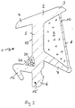
- the sealing profile shown there in cross section is approximately T-shaped.
- the crossbar of the T-shape is inclined to the horizontal and consists of an upper profile part 2, at the end of which the upper sealing lip 3 and the covering lip 4 are located.
- the trunk of the T-shape is formed by the vertical profile part 5, at the end of which the sealing foot 6 is located.
- a lower sealing lip 7 that extends obliquely downwards spreads out.
- the end of the lower sealing lip 7, viewed in the horizontal direction, is further away from the vertical profile part 5 than the end of the upper sealing lip 3.
- the end of the lower sealing lip 7 is connected to the upper profile part 2 via a scribing lip 8 so that the upper sealing lip 3 presents itself as a cantilevered, free profile part.
- the upper profile part 2, the scribing lip 8, the lower sealing lip 7 and parts of the vertical profile part 5 enclose a cavity 9 which is filled with a sealant.
- FIG. 1 The arrangement of a predetermined tear point 10 can be seen in FIG. 1 in the upper region of the scribing lip 8.
- the functioning and task of the individual parts can best be explained with reference to FIG. 4.
- FIG. 2 shows a cross section through a further sealing profile according to the invention, which differs from the sealing profile shown in FIG. 1 by the additional arrangement of a further cavity 11 and the arrangement of a projecting sealing lip 12.
- the additional cavity 11 is also filled with a sealant.
- the other parts correspond essentially to the sealing profile according to FIG. 1.
- the task and mode of operation of the individual parts result from the description of FIG. 4.
- the sealing lip 12 functions primarily as an anchoring foot.
- FIG. 3 shows a further variant of the sealing profile 1 according to the invention, which essentially corresponds to the sealing profile 1 shown in FIG. 1.
- the only difference in the sealing profile 1 according to FIG. 3 is the arrangement of a further cavity 13 which is arranged adjacent to the cavity 9 and is separated from it by a sealing web part 14.
- the further cavity 13 is only filled with air, so it has no sealant.
- the cavity 13 has a compensating function in the installed state of the sealing profile.
- the scribe lip 8 tears when the window pane is installed and pressed against the sealing profile 1, as a result of which the cavity 9 and thus also the sealant therein are compressed.
- the cavity 13 is reduced accordingly, so that it is ensured that no sealant can escape from the sealing profile 1.
- the sealing web part which lies between the filled cavity 9 and the further cavity 13, is designed to be correspondingly thinner.
- the thickness of the sealing web part 14 can be varied, so that a pressure which is passed on to the further cavity 13 via the sealant of the cavity 9 requires a correspondingly greater or smaller compression of the cavity 13.
- a double-sided adhesive tape 15 is provided over part of the height of the vertical profile part 5. This double-sided adhesive tape 15 is actually not necessary in the sealing profile shown in FIGS. 2 + 5, but can nevertheless be provided as an additional measure.
- All sealing profiles have an inserted thread 16 'in the area of the sealing foot 6.
- the thread 16 ' is arranged in the sealing foot 6 so that it is enclosed on all sides by the material of the sealing profile 1. In the miter area, it is necessary to cut the sealing profile 1 accordingly. The incision is made shortly before the thread 16 '.
- the thread 16 ' now ensures that the resulting weak point in the miter area does not tear during assembly and in the installed state, since the thread can absorb tensile stresses. Because the thread in the miter area remains undamaged, the sealing profile 1 does not gap in the miter area even if, for example, the sealing profile 1 is shortened in its longitudinal direction due to external influences, since the thread also creates tensile stresses in the miter area installed state can safely record.
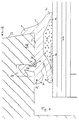
- Fig. 4 shows the sealing profile 1 of FIG. 2 in the installed state.
- the weather side of a wooden window corner area is shown in cross section.
- the sealing profile 1 has a projecting sealing lip 12 which engages in the horizontal recess or groove 17 of the window frame 16 and interacts with it the cover lip 4 clamps on the projecting part 18 of the window frame.
- the window pane or the insulating glass 19 shown is first clogged in the window frame 16. The block is not shown. Then the insulating glass 19 is pressed against the sealing profile 1. Due to the oblique arrangement of the upper sealing lip 3 and the lower sealing lip 7, they each deflect outwards, i.e. the upper sealing lip 3 is pressed upwards and the lower sealing lip 7 downwards. The scribing lip 8 is stretched and is thus under tension.
- the sealing lip 8 Since the sealing lip 8 is thin in relation to the other profile cross-sectional parts and also has a predetermined tear point 10, the scribing lip 8 will tear open during the pressing of the insulating glass 19 against the sealing profile 1.
- the sealing material located in the cavity 9 can thus emerge and seal on the insulating glass 19.
- the scribing lip 8 can also have a non-illustrated, prestressed insert on the side facing the cavity 9 or can be designed in such a way that the named side is under greater tension than the opposite side. Because of this pretension, the scribing lip 8 will roll up, starting at the predetermined breaking point 10, so that an even larger area is released in which the sealing material seals the insulating glass 19.
- the predetermined tear point 20 is arranged in a scribing lip 26 which seals the cavity 11 to the outside, the cross section of the further scribing lip 26 being thin in relation to the other profile cross sections.
- the predetermined tear point 20 is arranged so that it is exactly opposite the lower edge 21 in the installed state. Due to the contact pressure and due to the interaction between the lower edge 21 and the predetermined tear point 20, the additional cavity 11 is torn open and the sealing material located therein can escape and seal the area of the lower edge 21 of the projecting part 18.
- the seal described is intended to ensure that moisture does not penetrate into the interior on the side between window frame 16 and sealing profile 1. Due to the inclined surface 22 of the window frame 16 and the arrangement of the cover lip 4 penetration of moisture is largely prevented, but it can still happen that moisture penetrates into the space between the window frame 16 and the sealing profile due to damage or other circumstances. So that this moisture cannot penetrate into the interior between the window frame and the insulating glass 19, the lower edge 21 of the projecting part 18 is additionally sealed by the sealant located in the hollow chamber 11.
- a first protection against the ingress of moisture is therefore first of all due to the inclined surface 22 of the window frame 16 and the cover lip 4 and the upper sealing lip 3. Reliable and safe protection against the ingress of moisture and to prevent heat loss is then provided in the hollow chambers 9 and 11 located sealing material guaranteed.
- the sealing material is protected from premature signs of aging, since it is not directly exposed to the weather, but is protected by the sealing profile 1.
- polysulfides eg thiokol
- acrylic resins or acrylic rubber or the like can also be used.
- FIG. 5 shows a further variant of a sealing profile 1 according to the invention according to FIG. 1 in the clamped state on the window frame 16.
- the essential difference between the sealing profile 1 from FIG. 5 and the sealing profile 1 from FIG. 1 is the arrangement of a step 23 in the central region of the vertical profile part 5.
- the window frame 16 is designed such that it is on its vertical side facing the sealing profile jumps back, so that seen in the vertical direction, an extension 24 is formed.
- the distance between the underside of the covering lip 4 and the step 23 corresponds to the height of the extension piece 24.
- a double-sided adhesive tape 15 can also be provided on the surface of the sealing profile 1 opposite the attachment piece 24.
- sealing profile 1 shown in FIG. 5 It is also possible with the sealing profile 1 shown in FIG. 5 to subsequently press the sealing profile 1 into the gap between the window frame 16 and the window pane when the window pane is already installed.
- the correct and firm fit of the sealing profile 1 is ensured in that the step-like cross-sectional widening 25 of the vertical profile part snaps under the extension 24 of the window frame 16.
- the snapped-in state can be recognized by the fact that the sealing profile 1, in the snapped-in state, bears in the upper region under tension against the window frame 16 and against the window pane.
- the sealing profile 1 can also be used in other than wooden window frames, for example also plastic or aluminum window frames, the advantages being particularly evident in the sealing of wooden windows.
- a further cavity 11 can be provided in the corner region between the upper cover lip 4 and the vertical profile part 5, the predetermined tear point 20 then being oriented approximately obliquely downwards.
Landscapes
- Engineering & Computer Science (AREA)
- Civil Engineering (AREA)
- Structural Engineering (AREA)
- Securing Of Glass Panes Or The Like (AREA)
- Glass Compositions (AREA)
- Materials For Medical Uses (AREA)
- Diaphragms For Electromechanical Transducers (AREA)
- Secondary Cells (AREA)
Claims (10)
- Joint profilé pour réaliser l'étanchéité entre un cadre de fenêtre (16) en bois et une vitre (19) comportant une première partie qui assure l'étanchéité avec le cadre de fenêtre (16) et une deuxième partie qui assure l'étanchéité avec la vitre (19), au moins une cavité (9, 11) qui est aménagée dans la direction longitudinale du joint profilé (1) et est destinée à recevoir une masse d'étanchéité qui, avec des lèvres d'étanchéité, permet d'obtenir une étanchéité avec la vitre (19) et/ou le cadre de fenêtre (16), une lèvre de recouvrement (4) supérieure au niveau de la première partie qui est en contact d'étanchéité avec une partie de cadre (18) et des lèvres d'étanchéité (3, 7)supérieure et inférieure au niveau de la deuxième partie qui délimitent une paroi fine (8) de la cavité (9) et qui, avec la masse d'étanchéité contenue dans la cavité (9), viennent en contact étanche avec la vitre (19) lors du montage, caractérisé par le fait que la lèvre d'étanchéité (3) supérieure et la lèvre d'étanchéité (7) inférieure peuvent être écartée et par le fait qu'après application de la vitre (19), un point destiné à la rupture (10) de la paroi (8) fine se rompt et la surface de la vitre (19) qui est couverte par la masse d'étanchéité est limitée par les lèvres d'étanchéité (3, 7) écartées.
- Joint profilé selon la revendication 1, caractérisé par le fait que la première partie qui assure l'étanchéité avec le cadre de fenêtre (16) comporte une cavité (11) supplémentaire qui est remplie de masse d'étanchéité et est pourvue d'une paroi (26) de faible épaisseur et par le fait qu'au montage du joint profilé (1), un point destiné à la rupture (20) de la paroi (26) de faible épaisseur est situé en regard d'un angle (21) du cadre de fenêtre (16).
- Joint profilé selon la revendication 1 ou 2, caractérisé par le fait qu'il est prévu au voisinage de la cavité remplie de masse d'étanchéité au moins une cavité (13) remplie d'air.
- Joint profilé selon la revendication 3, caractérisé par le fait que la cavité (13) remplie d'air est séparée de la cavité (9) remplie de masse d'étanchéité par une cloison (14) du joint et par le fait qu'on peut régler la compression de la cavité (9) ou des cavités (13, 9) au moyen de l'épaisseur de la cloison (14) et de la section de la cavité (13) remplie d'air.
- Joint profilé selon l'une des revendications 1 à 4, caractérisé par le fait que les parois des cavités (9, 11) remplies, tournées vers la zone avec laquelle il s'agit de réaliser l'étanchéité, comportent une garniture continue qui est disposée dans la partie tournée vers la cavité remplie, est précontrainte et s'étend dans la direction longitudinale du joint profilé (1) aux fins de rouler au moins partiellement les parois (8, 26) de faible épaisseur après rupture des points destinés à la rupture (10, 20).
- Joint profilé selon l'une des revendications 1 à 5, caractérisé par le fait qu'une lèvre d'étanchéité (12) saillante servant de pied d'ancrage est disposée dans la première partie du joint profilé (1), dans la région de la cavité (11).
- Joint profilé selon l'une des revendications 1 à 6, caractérisé par le fait qu'il est prévu une partie (5) profilée verticale qui, sur sa surface tournée vers le cadre de fenêtre est pourvue d'une bande adhésive double face (15).
- Joint profilé selon l'une des revendications 1 à 7, caractérisé par le fait que le joint profilé (1) est en élastomère, notamment en PCV ou en thermo-caoutchouc/TPE.
- Procédé de fabrication par extrusion d'un joint profilé selon l'une des revendications 1 à 8 comportant une ou plusieurs cavités contiinues qui s'étendent dans la direction longitudinale du joint profilé, caractérisé par le fait qu'après réalisation des cavités on injecte dans certaines de celles-ci une masse d'étanchéité différente du matériau du joint profilé, notamment une masse d'étanchéité à base de silicone, à la suite de quoi on extrude le joint profilé pourvu de la masse d'étanchéité.
- Procédé selon la revendication 9, caractérisé par le fait que lors de l'extrusion du joint profilé on place un fil à l'intérieur d'une partie du profilé et par le fait que le fil est entièrement entouré par le matériau constituant le joint profilé.
Applications Claiming Priority (2)
| Application Number | Priority Date | Filing Date | Title |
|---|---|---|---|
| DE4006983A DE4006983C2 (de) | 1990-03-06 | 1990-03-06 | Dichtungsprofil |
| DE4006983 | 1990-03-06 |
Publications (3)
| Publication Number | Publication Date |
|---|---|
| EP0446776A2 EP0446776A2 (fr) | 1991-09-18 |
| EP0446776A3 EP0446776A3 (en) | 1992-05-20 |
| EP0446776B1 true EP0446776B1 (fr) | 1994-06-29 |
Family
ID=6401516
Family Applications (1)
| Application Number | Title | Priority Date | Filing Date |
|---|---|---|---|
| EP91103436A Expired - Lifetime EP0446776B1 (fr) | 1990-03-06 | 1991-03-06 | Joint d'étanchéité profilé |
Country Status (4)
| Country | Link |
|---|---|
| EP (1) | EP0446776B1 (fr) |
| AT (1) | ATE108001T1 (fr) |
| DE (2) | DE4006983C2 (fr) |
| DK (1) | DK0446776T3 (fr) |
Families Citing this family (10)
| Publication number | Priority date | Publication date | Assignee | Title |
|---|---|---|---|---|
| DE4421804C2 (de) * | 1994-06-22 | 1998-02-19 | Deflex Dichtsysteme Gmbh | Anordnung zur Abdichtung |
| FR2747172B1 (fr) * | 1996-04-03 | 1998-05-29 | Heurteaux | Bande profilee de largeur modulable, en particulier pour la formation d'un joint ou d'une goulotte |
| DE19704094A1 (de) * | 1997-02-04 | 1998-08-06 | Volkswagen Ag | Dichtung |
| CN1093211C (zh) * | 1998-05-09 | 2002-10-23 | 朱铁全 | 铝、塑门窗密封胶条的一种制造工艺 |
| EP1845229B1 (fr) | 2006-04-13 | 2012-11-14 | Dätwyler Ag Schweizerische Kabel-, Gummi- Und Kunststoffwerke | Elément d'étanchéité pour vitrage |
| DE102008024609A1 (de) * | 2008-05-21 | 2009-12-10 | Artweger Gmbh & Co. | Dichtungsprofil |
| US8584426B2 (en) | 2010-06-04 | 2013-11-19 | Milgard Manufacturing Incorporated | Sash binder |
| CN108360965A (zh) * | 2018-04-26 | 2018-08-03 | 刘家栋 | 一种密封条及使用该密封条的门、窗 |
| CN116181197A (zh) * | 2021-11-26 | 2023-05-30 | 南通市开泰高分子材料有限公司 | 一种玻璃窗聚硫密封胶条 |
| DE102023211382A1 (de) * | 2023-11-15 | 2025-05-15 | Volkswagen Aktiengesellschaft | Dichtung, Verfahren zur Montage einer Dichtung und Verfahren zur Herstellung einer Dichtung, insbesondere für ein Kraftfahrzeug |
Family Cites Families (11)
| Publication number | Priority date | Publication date | Assignee | Title |
|---|---|---|---|---|
| DE1129273B (de) * | 1957-12-12 | 1962-05-10 | Pawling Rubber Corp | Elastisches Scheiben- oder Platteneinfassprofil, insbesondere zum Abdichten von Fensterscheiben gegenueber dem Rahmen |
| US3061895A (en) * | 1960-08-05 | 1962-11-06 | Pawling Rubber Corp | Resilient caulking seal |
| DE3048744A1 (de) * | 1980-12-23 | 1982-07-22 | Metzeler Kautschuk GmbH, 8000 München | Anordnung zum abdichten einer mehrscheibenverglasung |
| DE8120340U1 (de) * | 1981-07-11 | 1981-11-05 | SCHÜCO Heinz Schürmann GmbH & Co, 4800 Bielefeld | "fenster oder tuer mit einem zwischen einer glashalteleiste und der scheibe einsetzbaren dichtungsprofil" |
| DE8131774U1 (de) * | 1981-10-30 | 1982-04-01 | Deventer GmbH & Co, 8000 München | "dichtungsprofil" |
| DE3415347A1 (de) * | 1983-04-28 | 1984-10-31 | Huber & Suhner Ag Kabel-, Kautschuk-, Kunststoffwerke, Herisau | Gummielastisches profil |
| GB2140068B (en) * | 1983-05-20 | 1986-03-19 | Draftex Ind Ltd | Window glass mounting |
| GB8422322D0 (en) * | 1984-09-04 | 1984-10-10 | Schlegel Uk Holdings | Extruded elastomer seals |
| DE8534283U1 (de) * | 1985-12-05 | 1986-02-20 | Metzeler Kautschuk GmbH, 8000 München | Verglasungsdichtung mit geringer Faltenbildung |
| DE3619583A1 (de) * | 1986-06-11 | 1987-12-17 | Pirelli Reifenwerke | Strangartiges dichtungsprofil |
| DE3706503A1 (de) * | 1987-02-27 | 1988-09-08 | Deventer Profile | Verfahren zum abdichten von scheiben aus glas o.ae. in fenstern, tueren oder dgl. sowie elastische strangdichtung zur durchfuehrung des verfahrens |
-
1990
- 1990-03-06 DE DE4006983A patent/DE4006983C2/de not_active Expired - Fee Related
-
1991
- 1991-03-06 DK DK91103436.1T patent/DK0446776T3/da active
- 1991-03-06 EP EP91103436A patent/EP0446776B1/fr not_active Expired - Lifetime
- 1991-03-06 AT AT91103436T patent/ATE108001T1/de not_active IP Right Cessation
- 1991-03-06 DE DE59102045T patent/DE59102045D1/de not_active Expired - Fee Related
Also Published As
| Publication number | Publication date |
|---|---|
| DE4006983A1 (de) | 1991-09-12 |
| ATE108001T1 (de) | 1994-07-15 |
| EP0446776A2 (fr) | 1991-09-18 |
| DE59102045D1 (de) | 1994-08-04 |
| DK0446776T3 (da) | 1994-11-07 |
| DE4006983C2 (de) | 1994-06-16 |
| EP0446776A3 (en) | 1992-05-20 |
Similar Documents
| Publication | Publication Date | Title |
|---|---|---|
| EP0029984B1 (fr) | Verre laminé isolant et procédé pour sa fabrication | |
| EP0341269B1 (fr) | Profile de recouvrement pour vitrages ou elements de remplissage de facade | |
| DE4326115A1 (de) | Profildichtung für Fenster und sowie Verfahren und Vorrichtung zu ihrer Anbringung | |
| EP0446776B1 (fr) | Joint d'étanchéité profilé | |
| EP3260644B1 (fr) | Porte-verre et son procédé de montage | |
| DE29901972U1 (de) | Rahmenprofil für Holz-Metall-Fenster oder -Türen | |
| DE69734632T2 (de) | Wärmedämmender Trennprofilkörper zum Einsetzen zwischen Aluminiumprofilen zur Verwendung bei der Herstellung von Türen und Fenster | |
| DE9002593U1 (de) | Dichtungsprofil | |
| AT391518B (de) | Verfahren und strangdichtung zum abdichten von scheiben aus glas und dgl. in raumabschlussorganen | |
| EP1860250A2 (fr) | Profile d'étanchéité | |
| EP0651839B1 (fr) | Conduit de drainage | |
| DE4039386C2 (de) | Elastisches Strangdichtungsprofil zum Abdichten von Verglasungen in Flügeln von Holzfenstern oder Holztüren | |
| EP1533531B2 (fr) | Procédé de fabrication d'un assemblage par vissage étanche à l'humidité | |
| DE3414958A1 (de) | Verklotzungssystem | |
| DE19756899C2 (de) | Verfahren zur Montage von Scheiben und vorgefertigte Rahmenleiste zur Ausbildung eines geschlossenen Rahmens für Fensterscheiben | |
| DE2021612A1 (de) | Vorrichtung zur Einfassung und Befestigung von Scheiben u.dgl. | |
| DE4401667A1 (de) | Abstandshalterrahmen für eine Isolierscheibe und Vorrichtung zu seiner Herstellung | |
| DE19612491A1 (de) | Glasdichtungsleiste für Rahmen von Fenstern oder Türen mit eingesetzter Verglasung | |
| DE102016120279A1 (de) | Abdichtungselement und Verfahren zum Abdichten eines Fensterbankabschlusses | |
| DE29500285U1 (de) | Befestigungsvorrichtung für mindestens zwei Fassadenelemente | |
| DE8615696U1 (de) | Strangartiges Dichtungsprofil | |
| DE29609162U1 (de) | Strangförmige Dichtung | |
| DE7933613U1 (de) | Von einem rahmen aus kunststoff- profilstaeben umgebene isolierglaseinheit | |
| DE4332053C2 (de) | Anschlußprofil zum Abdichten von Fugen zwischen Fensterprofilrahmen und Fensterbänken | |
| DE3528388A1 (de) | Elastische profildichtung fuer isolierverglasungen |
Legal Events
| Date | Code | Title | Description |
|---|---|---|---|
| PUAI | Public reference made under article 153(3) epc to a published international application that has entered the european phase |
Free format text: ORIGINAL CODE: 0009012 |
|
| AK | Designated contracting states |
Kind code of ref document: A2 Designated state(s): AT BE CH DE DK ES FR GB GR IT LI LU NL SE |
|
| PUAL | Search report despatched |
Free format text: ORIGINAL CODE: 0009013 |
|
| AK | Designated contracting states |
Kind code of ref document: A3 Designated state(s): AT BE CH DE DK ES FR GB GR IT LI LU NL SE |
|
| 17P | Request for examination filed |
Effective date: 19921117 |
|
| 17Q | First examination report despatched |
Effective date: 19930304 |
|
| GRAA | (expected) grant |
Free format text: ORIGINAL CODE: 0009210 |
|
| AK | Designated contracting states |
Kind code of ref document: B1 Designated state(s): AT BE CH DE DK ES FR GB GR IT LI LU NL SE |
|
| PG25 | Lapsed in a contracting state [announced via postgrant information from national office to epo] |
Ref country code: GR Free format text: LAPSE BECAUSE OF FAILURE TO SUBMIT A TRANSLATION OF THE DESCRIPTION OR TO PAY THE FEE WITHIN THE PRESCRIBED TIME-LIMIT Effective date: 19940629 Ref country code: ES Free format text: THE PATENT HAS BEEN ANNULLED BY A DECISION OF A NATIONAL AUTHORITY Effective date: 19940629 |
|
| REF | Corresponds to: |
Ref document number: 108001 Country of ref document: AT Date of ref document: 19940715 Kind code of ref document: T |
|
| REF | Corresponds to: |
Ref document number: 59102045 Country of ref document: DE Date of ref document: 19940804 |
|
| ITF | It: translation for a ep patent filed | ||
| ET | Fr: translation filed | ||
| GBT | Gb: translation of ep patent filed (gb section 77(6)(a)/1977) |
Effective date: 19940926 |
|
| REG | Reference to a national code |
Ref country code: DK Ref legal event code: T3 |
|
| EAL | Se: european patent in force in sweden |
Ref document number: 91103436.1 |
|
| PG25 | Lapsed in a contracting state [announced via postgrant information from national office to epo] |
Ref country code: AT Effective date: 19950306 |
|
| PG25 | Lapsed in a contracting state [announced via postgrant information from national office to epo] |
Ref country code: LU Free format text: LAPSE BECAUSE OF NON-PAYMENT OF DUE FEES Effective date: 19950331 Ref country code: LI Effective date: 19950331 Ref country code: CH Effective date: 19950331 |
|
| PLBE | No opposition filed within time limit |
Free format text: ORIGINAL CODE: 0009261 |
|
| STAA | Information on the status of an ep patent application or granted ep patent |
Free format text: STATUS: NO OPPOSITION FILED WITHIN TIME LIMIT |
|
| 26N | No opposition filed | ||
| REG | Reference to a national code |
Ref country code: CH Ref legal event code: PL |
|
| PGFP | Annual fee paid to national office [announced via postgrant information from national office to epo] |
Ref country code: GB Payment date: 19980213 Year of fee payment: 8 |
|
| PGFP | Annual fee paid to national office [announced via postgrant information from national office to epo] |
Ref country code: FR Payment date: 19990127 Year of fee payment: 9 |
|
| PGFP | Annual fee paid to national office [announced via postgrant information from national office to epo] |
Ref country code: SE Payment date: 19990305 Year of fee payment: 9 |
|
| PG25 | Lapsed in a contracting state [announced via postgrant information from national office to epo] |
Ref country code: GB Free format text: LAPSE BECAUSE OF NON-PAYMENT OF DUE FEES Effective date: 19990306 |
|
| PGFP | Annual fee paid to national office [announced via postgrant information from national office to epo] |
Ref country code: DK Payment date: 19990310 Year of fee payment: 9 |
|
| PGFP | Annual fee paid to national office [announced via postgrant information from national office to epo] |
Ref country code: BE Payment date: 19990323 Year of fee payment: 9 |
|
| PGFP | Annual fee paid to national office [announced via postgrant information from national office to epo] |
Ref country code: NL Payment date: 19990329 Year of fee payment: 9 |
|
| PGFP | Annual fee paid to national office [announced via postgrant information from national office to epo] |
Ref country code: DE Payment date: 19990331 Year of fee payment: 9 |
|
| GBPC | Gb: european patent ceased through non-payment of renewal fee |
Effective date: 19990306 |
|
| PG25 | Lapsed in a contracting state [announced via postgrant information from national office to epo] |
Ref country code: DK Free format text: LAPSE BECAUSE OF NON-PAYMENT OF DUE FEES Effective date: 20000306 |
|
| PG25 | Lapsed in a contracting state [announced via postgrant information from national office to epo] |
Ref country code: SE Free format text: LAPSE BECAUSE OF NON-PAYMENT OF DUE FEES Effective date: 20000307 |
|
| PG25 | Lapsed in a contracting state [announced via postgrant information from national office to epo] |
Ref country code: BE Free format text: LAPSE BECAUSE OF NON-PAYMENT OF DUE FEES Effective date: 20000331 |
|
| BERE | Be: lapsed |
Owner name: HPP PROFILE G.M.B.H. Effective date: 20000331 |
|
| PG25 | Lapsed in a contracting state [announced via postgrant information from national office to epo] |
Ref country code: NL Free format text: LAPSE BECAUSE OF NON-PAYMENT OF DUE FEES Effective date: 20001001 |
|
| EUG | Se: european patent has lapsed |
Ref document number: 91103436.1 |
|
| PG25 | Lapsed in a contracting state [announced via postgrant information from national office to epo] |
Ref country code: FR Free format text: LAPSE BECAUSE OF NON-PAYMENT OF DUE FEES Effective date: 20001130 |
|
| NLV4 | Nl: lapsed or anulled due to non-payment of the annual fee |
Effective date: 20001001 |
|
| REG | Reference to a national code |
Ref country code: DK Ref legal event code: EBP |
|
| REG | Reference to a national code |
Ref country code: FR Ref legal event code: ST |
|
| PG25 | Lapsed in a contracting state [announced via postgrant information from national office to epo] |
Ref country code: DE Free format text: LAPSE BECAUSE OF NON-PAYMENT OF DUE FEES Effective date: 20010103 |
|
| PG25 | Lapsed in a contracting state [announced via postgrant information from national office to epo] |
Ref country code: IT Free format text: LAPSE BECAUSE OF NON-PAYMENT OF DUE FEES;WARNING: LAPSES OF ITALIAN PATENTS WITH EFFECTIVE DATE BEFORE 2007 MAY HAVE OCCURRED AT ANY TIME BEFORE 2007. THE CORRECT EFFECTIVE DATE MAY BE DIFFERENT FROM THE ONE RECORDED. Effective date: 20050306 |