EP0446676A2 - Anlage zur Herstellung von Ammoniumpolyphosphat - Google Patents
Anlage zur Herstellung von Ammoniumpolyphosphat Download PDFInfo
- Publication number
- EP0446676A2 EP0446676A2 EP91102445A EP91102445A EP0446676A2 EP 0446676 A2 EP0446676 A2 EP 0446676A2 EP 91102445 A EP91102445 A EP 91102445A EP 91102445 A EP91102445 A EP 91102445A EP 0446676 A2 EP0446676 A2 EP 0446676A2
- Authority
- EP
- European Patent Office
- Prior art keywords
- reactor
- plant according
- bunker
- discharge
- mixing apparatus
- Prior art date
- Legal status (The legal status is an assumption and is not a legal conclusion. Google has not performed a legal analysis and makes no representation as to the accuracy of the status listed.)
- Granted
Links
Images
Classifications
-
- C—CHEMISTRY; METALLURGY
- C01—INORGANIC CHEMISTRY
- C01B—NON-METALLIC ELEMENTS; COMPOUNDS THEREOF; METALLOIDS OR COMPOUNDS THEREOF NOT COVERED BY SUBCLASS C01C
- C01B25/00—Phosphorus; Compounds thereof
- C01B25/16—Oxyacids of phosphorus; Salts thereof
- C01B25/26—Phosphates
- C01B25/38—Condensed phosphates
- C01B25/40—Polyphosphates
- C01B25/405—Polyphosphates of ammonium
-
- C—CHEMISTRY; METALLURGY
- C05—FERTILISERS; MANUFACTURE THEREOF
- C05B—PHOSPHATIC FERTILISERS
- C05B13/00—Fertilisers produced by pyrogenic processes from phosphatic materials
- C05B13/06—Alkali and alkaline earth meta- or polyphosphate fertilisers
Definitions
- the present invention relates to a plant for the production of substantially water-insoluble, chain-like ammonium polyphosphate from ammonium orthophosphate and phosphorus pentoxide in the presence of gaseous ammonia, which consists of a reactor with rotating mixing, kneading and comminuting tools in its interior and a feed pipe for the solid starting materials, one Inlet pipe for ammonia, a gas discharge pipe and a discharge line for the reaction product, which are connected in terms of flow to the interior of the reactor.
- the disadvantage here is that the reactor designed as a kneader is stable due to its high mechanical stress Must have design. In addition, its interior and the double Z blades must be made of a highly abrasion-resistant metal alloy. The device is therefore very investment-intensive.
- the present invention relates to a plant for the production of substantially water-insoluble, chain-like ammonium polyphosphate, which consists of a reactor with rotatable mixing, kneading and comminuting tools, the discharge line of the reactor being connected to a mixing apparatus in terms of material flow, a discharge member in the discharge line is arranged and the discharge member is controlled by the current consumption of the drive motor of the reactor.
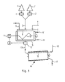
- the solid raw materials (ammonium orthophosphate and phosphorus pentoxide) are introduced from storage containers (1,1 ') via weighing devices (2,2') through a feed line 3 into the reactor 4.
- the reactor 4 consists of a closed trough, which is provided with a heating jacket 5, the nozzle (6,6 ') for the supply or discharge of a heating medium.
- a first gas distribution pipe 8 is arranged in the upper area of the reactor 4 and ammonia can be applied to it via a first gas supply pipe 7. Excess ammonia can 9 escape.
- Rotating tools 10 are located in the reactor 4 and are attached to a horizontal axis.
- a rotary kiln 14 is connected via a discharge line 13, in which a shut-off device 12 is located, to the material flow with the lower region of the reactor 4.
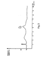
- the shut-off device 12 is controlled in dependence on the current consumption of the drive motor 11 at the reactor 4 in such a way that the shut-off device 12 is opened after passing through a second current peak (see FIG. 2 - arrow).
- a second gas distribution pipe 15 which can be acted upon by ammonia via a second gas feed pipe 16.
- the rotary kiln 14 is also provided with a discharge pipe 17.
- a bunker Since a rotary kiln as well as a plate dryer or a fluidized bed reactor can only be operated continuously, but reaction material can only be discharged intermittently from the reactor designed as a kneader, a bunker, not shown, must be located between the reactor and the rotary kiln as an intermediate store. For energy reasons, the bunker should be designed as a hot bunker and be equipped with a device for comminuting agglomerates. When using a kneading mixer as a mixer, the bunker can be omitted in batch operation.
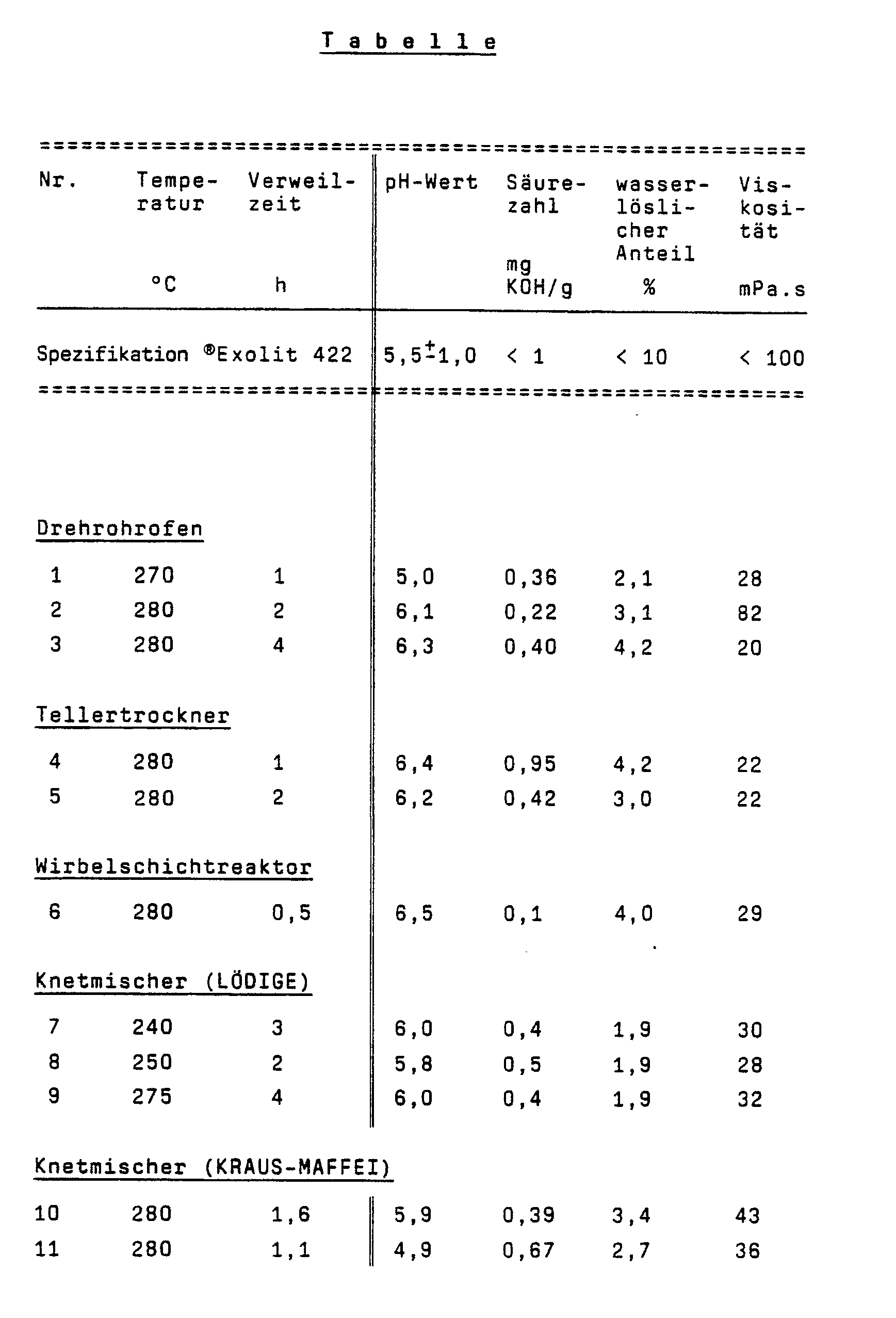
- ammonium polyphosphates obtained in the plant according to the invention with regard to their characteristics (pH value, acid number, water-soluble components, viscosity), which can be determined by chemical and X-ray analysis, and the specification of the type ®Exolit 422 (HOECHST AG, Frankfurt ; 1989) compared.
Landscapes
- Chemical & Material Sciences (AREA)
- Organic Chemistry (AREA)
- Inorganic Chemistry (AREA)
- Mixers Of The Rotary Stirring Type (AREA)
- Fertilizers (AREA)
- Organic Low-Molecular-Weight Compounds And Preparation Thereof (AREA)
- Physical Or Chemical Processes And Apparatus (AREA)
- Agricultural Chemicals And Associated Chemicals (AREA)
- Compounds Of Alkaline-Earth Elements, Aluminum Or Rare-Earth Metals (AREA)
Abstract
Description
- Die vorliegende Erfindung betrifft eine Anlage zur Herstellung von im wesentlichen wasserunlöslichem, kettenförmigem Ammoniumpolyphosphat aus Ammoniumorthophosphat und Phosphorpentoxid in Gegenwart von gasförmigem Ammoniak, welche aus einem Reaktor mit drehbaren Misch-, Knet- und Zerkleinerungswerkzeugen in seinem Innenraum und einem Zuführungsrohr für die festen Ausgangsstoffe, einem Einleitungsrohr für Ammoniak, einem Gasableitungsrohr sowie einer Austragsleitung für das Reaktionsprodukt besteht, welche strömungsmäßig mit dem Innenraum des Reaktors verbunden sind.
- Aus der US-PS 3 978 195 ist ein Verfahren zur Herstellung von im wesentlichen wasserunlöslichen, kettenförmigen Ammoniumpolyphosphaten bekannt, bei welchem äquimolare Mengen von Ammoniumorthophosphat und Phosphorpentoxid in Gegenwart von Ammoniak auf Temperaturen zwischen 170 und 350 °C unter ständigem Mischen, Kneten und Zerkleinern zur Reaktion gebracht werden, wobei in der ersten Phase bei teigigem Reaktionsgemisch mit relativ geringer Drehzahl (15 bis 21 Upm) und in einer zweiten Phase nach Entstehen eines feinteiligen Produktes mit hoher Drehzahl (49 bis 64 Upm) gedreht wird, so daß sich aus dem Produkt eine Art Wirbelschicht bildet. Als Apparat zum Mischen, Kneten und Zerkleinern der Einsatzstoffe bzw. des Reaktionsproduktes wird dabei ein mit Mischwerkzeugen versehener Reaktor verwendet, wobei als Mischwerkzeuge zwei parallel angeordnete, um ihre waagerechten Achsen drehbare Doppel-Z-Schaufeln dienen.
- Nachteilig ist dabei, daß der als Kneter ausgeführte Reaktor wegen seiner starken mechanischen Belastung eine stabile Bauart aufweisen muß. Darüber hinaus müssen sein Innenraum und die Doppel-Z-Schaufeln aus einer hochabriebfesten Metall-Legierung bestehen. Der Apparat ist daher sehr investitionsintensiv.
- Es wurde nun überraschend gefunden, daß ein solch aufwendiger Kneter für die erste Phase der Herstellung von Ammoniumpolyphosphat, nämlich für die Vermischung von Ammoniumorthophosphat und Phosphorpentoxid sowie die Knetung der teigigen Masse unentbehrlich ist, daß jedoch nach Zerfall der teigigen Masse in ein krümeliges Produkt in der zweiten Phase ein weniger aufwendiger Mischapparat einsetzbar ist.
- Im einzelnen betrifft die vorliegende Erfindung eine Anlage zur Herstellung von im wesentlichen wasserunlöslichem, kettenförmigem Ammoniumpolyphosphat, welche aus einem Reaktor mit drehbaren Misch-, Knet- und Zerkleinerungswerkzeugen besteht, wobei die Austragsleitung des Reaktors mit einem Mischapparat materialströmungsmäßig verbunden ist, in der Austragsleitung ein Austragsorgan angeordnet ist und das Austragsorgan von der Stromaufnahme des Antriebsmotors des Reaktors gesteuert wird.
- Die Anlage gemäß der Erfindung kann wahlweise auch noch dadurch weitergebildet sein, daß
- a) der Mischapparat ein Drehrohrofen ist,
- b) der Mischapparat ein Tellertrockner ist,
- c) der Mischapparat ein Wirbelschichtreaktor ist,
- d) der Mischapparat ein Knetmischer ist,
- e) materialströmungsmäßig zwischen dem Reaktor und dem Mischapparat ein Bunker angeordnet ist,
- f) der Bunker ein Heißbunker ist,
- g) der Bunker mit einer Einrichtung zur Zerkleinerung von Agglomeraten versehen ist,
- h) bei jeder Charge im Reaktor nach Durchlaufen des zweiten Strompeaks im Stromaufnahme-Zeit-Diagramm seines Antriebsmotors das Austragsorgan geöffnet und nach Entleerung des Reaktors geschlossen wird.
- Bei der erfindungsgemäßen Anlage ist beim Übergang des im Kneter befindlichen Materials von der teigigen Masse zum krümeligen Produkt zusätzliche mechanische Energie erforderlich. Dieses zusätzliche Energieerfordernis gibt sich im Stromaufnahme-Zeit-Diagramm des den Kneter antreibenden Elektromotors als Peak zu erkennen, der als Regelgröße verwendet wird.
- In der beigefügten Zeichnung ist eine Anlage gemäß der Erfindung schematisch dargestellt. Dabei zeigen:
- Fig. 1:
- die eigentliche Anlage im Schnitt;
- Fig. 2:
- die Stromaufnahmekurve des Antriebsmotors M des Reaktors.
- Aus Vorratsbehältern (1,1 ') werden die festen Rohstoffe (Ammoniumorthophosphat und Phosphorpentoxid) über Wägeeinrichtungen (2,2 ') durch eine Zuführungsleitung 3 in den Reaktor 4 eingeführt. Der Reaktor 4 besteht aus einem geschlossenen Trog, welcher mit einem Heizmantel 5 versehen ist, der Stutzen (6,6 ') für die Zu- bzw. Ableitung eines Heizmediums aufweist. Im oberen Bereich des Reaktors 4 ist ein erstes Gasverteilungsrohr 8 angeordnet, welches über ein erstes Gaszuleitungsrohr 7 mit Ammoniak beaufschlagbar ist. Überschüssiges Ammoniak kann über eine Abgasleitung 9 entweichen. Im Reaktor 4 befinden sich rotierende Werkzeuge 10, welche an einer waagerechten Achse befestigt sind. Ein Drehrohrofen 14 ist über eine Austragsleitung 13, in welchem sich ein Absperrorgan 12 befindet, materialströmungsmäßig mit dem unteren Bereich des Reaktors 4 verbunden. Dabei wird das Absperrorgan 12 in Abhängigkeit von der Stromaufnahme des Antriebsmotors 11 am Reaktor 4 derartig gesteuert, daß nach Durchlaufen eines zweiten Strompeaks (vergl. Figur 2 - Pfeil) das Absperrorgan 12 geöffnet wird. Im Drehrohrofen 14 befindet sich ein zweites Gasverteilungsrohr 15, welches über ein zweites Gaszuleitungsrohr 16 mit Ammoniak beaufschlagbar ist. Der Drehrohrofen 14 ist weiterhin mit einem Austragsrohr 17 versehen.
- Da ein Drehrohrofen ebenso wie ein Tellertrockner oder ein Wirbelschichtreaktor nur kontinuierlich betrieben werden kann, aus dem als Kneter ausgebildetem Reaktor Reaktionsgut aber nur diskontinuierlich ausgetragen werden kann, muß sich strömungsmäßig zwischen dem Reaktor und dem Drehrohrofen ein nicht dargestellter Bunker als Zwischenlager befinden. Der Bunker sollte aus Energiegründen als Heißbunker ausgebildet und mit einer Einrichtung zur Zerkleinerung von Agglomeraten versehen sein. Bei Verwendung eines Knetmischers als Mischapparat kann bei Batch-Betrieb der Bunker entfallen.
- In der folgenden Tabelle sind Ammoniumpolyphosphate, welche in der erfindungsgemäßen Anlage erhalten wurden, bezüglich ihrer durch chemische und röntgenographische Analyse ermittelbaren Charakteristika (pH-Wert, Säurezahl, wasserlösliche Anteile, Viskosität) aufgeführt und der Spezifikation der Type ®Exolit 422 (HOECHST AG, Frankfurt; 1989) gegenübergestellt.
Claims (9)
- Anlage zur Herstellung von im wesentlichen wasserunlöslichem, kettenförmigem Ammoniumpolyphosphat aus Ammoniumorthophosphat und Phosphorpentoxid in Gegenwart von gasförmigem Ammoniak, bestehend aus einem Reaktor mit drehbaren Misch-, Knet- und Zerkleinerungswerkzeugen in seinem Innenraum und einem Zuführungsrohr für die festen Ausgangsstoffe, einem Einleitungsrohr für Ammoniak, einem Gasableitungsrohr sowie einer Austragsleitung für das Reaktionsprodukt, welche strömungsmäßig mit dem Innenraum des Reaktors verbunden sind, dadurch gekennzeichnet, daß die Austragsleitung (13) des Reaktors (4) mit einem Mischapparat (14) materialströmungsmäßig verbunden ist, daß in der Austragsleitung (13) ein Austragsorgan (12) angeordnet ist, und daß das Austragsorgan (12) von der Stromaufnahme des Antriebsmotors (11) des Reaktors (4) gesteuert wird.
- Anlage nach Anspruch 1, dadurch gekennzeichnet, daß der Mischapparat (14) ein Drehrohrofen ist.
- Anlage nach Anspruch 1, dadurch gekennzeichnet, daß der Mischapparat (14) ein Tellertrockner ist.
- Anlage nach Anspruch 1, dadurch gekennzeichnet, daß der Mischapparat (14) ein Wirbelschichtreaktor ist.
- Anlage nach Anspruch 1, dadurch gekennzeichnet, daß der Mischapparat (14) ein Knetmischer ist.
- Anlage nach mindestens einem der Ansprüche 1 bis 5, dadurch gekennzeichnet, daß materialströmungsmäßig zwischen dem Reaktor (4) und dem Mischapparat (14) ein Bunker angeordnet ist.
- Anlage nach Anspruch 6, dadurch gekennzeichnet, daß der Bunker ein Heißbunker ist.
- Anlage nach Anspruch 6 oder 7, dadurch gekennzeichnet, daß der Bunker mit einer Einrichtung zur Zerkleinerung von Agglomeraten versehen ist.
- Anlage nach mindestens einem der Ansprüche 1 bis 8, dadurch gekennzeichnet, daß bei jeder Charge im Reaktor (4) nach Durchlaufen des zweiten Strompeaks im Stromaufnahme-Zeit-Diagramm seines Antriebsmotors (11) das Austragsorgan (12) geöffnet und nach Entleerung des Reaktors (4) geschlossen wird.
Priority Applications (1)
| Application Number | Priority Date | Filing Date | Title |
|---|---|---|---|
| AT91102445T ATE102593T1 (de) | 1990-03-05 | 1991-02-20 | Anlage zur herstellung von ammoniumpolyphosphat. |
Applications Claiming Priority (2)
| Application Number | Priority Date | Filing Date | Title |
|---|---|---|---|
| DE4006862A DE4006862A1 (de) | 1990-03-05 | 1990-03-05 | Anlage zur herstellung von ammoniumpolyphosphat |
| DE4006862 | 1990-03-05 |
Publications (3)
| Publication Number | Publication Date |
|---|---|
| EP0446676A2 true EP0446676A2 (de) | 1991-09-18 |
| EP0446676A3 EP0446676A3 (en) | 1991-10-30 |
| EP0446676B1 EP0446676B1 (de) | 1994-03-09 |
Family
ID=6401450
Family Applications (1)
| Application Number | Title | Priority Date | Filing Date |
|---|---|---|---|
| EP91102445A Expired - Lifetime EP0446676B1 (de) | 1990-03-05 | 1991-02-20 | Anlage zur Herstellung von Ammoniumpolyphosphat |
Country Status (11)
| Country | Link |
|---|---|
| US (1) | US5158752A (de) |
| EP (1) | EP0446676B1 (de) |
| JP (1) | JPH04214019A (de) |
| KR (1) | KR910016625A (de) |
| AT (1) | ATE102593T1 (de) |
| CA (1) | CA2036546A1 (de) |
| DE (2) | DE4006862A1 (de) |
| ES (1) | ES2051039T3 (de) |
| LT (1) | LT3588B (de) |
| LV (1) | LV10762B (de) |
| RU (1) | RU2025465C1 (de) |
Cited By (1)
| Publication number | Priority date | Publication date | Assignee | Title |
|---|---|---|---|---|
| EP0537475A1 (de) * | 1991-10-12 | 1993-04-21 | Hoechst Aktiengesellschaft | Verfahren zur Herstellung von Ammoniumpolyphosphat |
Families Citing this family (3)
| Publication number | Priority date | Publication date | Assignee | Title |
|---|---|---|---|---|
| DE19517499A1 (de) * | 1995-05-12 | 1996-11-14 | Budenheim Rud A Oetker Chemie | Verfahren zur Herstellung von Ammoniumpolyphosphat |
| RU2180891C1 (ru) * | 2000-12-22 | 2002-03-27 | Авдеев Виктор Васильевич | Установка для получения высококонденсированного полифосфата аммония |
| CN108275670B (zh) * | 2018-03-28 | 2024-02-02 | 山东昶盛阻燃新材料有限公司 | 一种ii型聚磷酸铵的生产方法 |
Family Cites Families (14)
| Publication number | Priority date | Publication date | Assignee | Title |
|---|---|---|---|---|
| US3171733A (en) * | 1961-09-08 | 1965-03-02 | Tennessee Valley Authority | High-analysis ammonium polyphosphate fertilizer |
| GB1128802A (en) * | 1964-11-16 | 1968-10-02 | Occidental Res & Eng | Improvements relating to the ammoniation of phosphoric acids |
| US3533737A (en) * | 1967-08-24 | 1970-10-13 | Tennessee Valley Authority | Ammonium polyphosphate produced at atmospheric pressure |
| DE1767205C2 (de) * | 1968-04-11 | 1978-06-01 | Hoechst AG, 6000 Frankfurt; Benckiser-Knapsack GmbH, 6802 Ladenburg | Verfahren zur Herstellung von Ammoniumpolyphosphaten |
| US3503706A (en) * | 1968-08-05 | 1970-03-31 | Grace W R & Co | Process for manufacturing ammonium polyphosphate |
| US3684724A (en) * | 1970-04-20 | 1972-08-15 | Stauffer Chemical Co | Process for making mixtures of sodium polyphosphates and sodium sulfate |
| GB1441449A (en) * | 1972-09-16 | 1976-06-30 | Gewerk Victor Chem Werke | Method of producing water-insoluble crystalline ammonium polyphosphates |
| SE408787B (sv) * | 1973-06-14 | 1979-07-09 | Hoechst Ag | Sett och anordning for framstellning av hyvudsakligen vattenolosliga kedjeformiga ammoniumpolyfosfater |
| US3949058A (en) * | 1973-12-20 | 1976-04-06 | Union Oil Company Of California | Production of ammonium polyphosphates |
| DE2414478C3 (de) * | 1974-03-26 | 1978-07-13 | Deutsche Gold- Und Silber-Scheideanstalt Vormals Roessler, 6000 Frankfurt | Aerogelartige strukturierte Kieselsäure und Verfahren zu ihrer Herstellung |
| US4028088A (en) * | 1975-12-17 | 1977-06-07 | Union Oil Company Of California | Soil amendment and method |
| CS230266B1 (en) * | 1982-02-15 | 1984-08-13 | Jan Teren | Method of and apparatus for continuously preparing melt of condensed ammonium phosphates |
| DE3208202A1 (de) * | 1982-03-06 | 1983-09-08 | Hoechst Ag, 6230 Frankfurt | Kettenfoermige, im wesentlichen wasserunloesliche ammoniumpolyphosphate und verfahren zu ihrer herstellung |
| DE3519349A1 (de) * | 1985-05-30 | 1986-12-04 | IKA-Maschinenbau Janke & Kunkel GmbH & Co KG, 7812 Bad Krozingen | Knetmaschine |
-
1990
- 1990-03-05 DE DE4006862A patent/DE4006862A1/de not_active Withdrawn
-
1991
- 1991-02-18 CA CA002036546A patent/CA2036546A1/en not_active Abandoned
- 1991-02-19 US US07/657,532 patent/US5158752A/en not_active Expired - Fee Related
- 1991-02-20 DE DE91102445T patent/DE59101124D1/de not_active Expired - Fee Related
- 1991-02-20 EP EP91102445A patent/EP0446676B1/de not_active Expired - Lifetime
- 1991-02-20 ES ES91102445T patent/ES2051039T3/es not_active Expired - Lifetime
- 1991-02-20 AT AT91102445T patent/ATE102593T1/de active
- 1991-03-02 KR KR1019910003426A patent/KR910016625A/ko not_active Withdrawn
- 1991-03-04 JP JP3037492A patent/JPH04214019A/ja not_active Withdrawn
- 1991-03-04 RU SU914894639A patent/RU2025465C1/ru active
-
1993
- 1993-05-04 LV LVP-93-281A patent/LV10762B/lv unknown
- 1993-11-05 LT LTIP1443A patent/LT3588B/lt not_active IP Right Cessation
Cited By (1)
| Publication number | Priority date | Publication date | Assignee | Title |
|---|---|---|---|---|
| EP0537475A1 (de) * | 1991-10-12 | 1993-04-21 | Hoechst Aktiengesellschaft | Verfahren zur Herstellung von Ammoniumpolyphosphat |
Also Published As
| Publication number | Publication date |
|---|---|
| LV10762B (en) | 1995-12-20 |
| CA2036546A1 (en) | 1991-09-06 |
| LT3588B (en) | 1995-12-27 |
| LV10762A (lv) | 1995-08-20 |
| DE4006862A1 (de) | 1991-09-12 |
| DE59101124D1 (de) | 1994-04-14 |
| ES2051039T3 (es) | 1994-06-01 |
| RU2025465C1 (ru) | 1994-12-30 |
| JPH04214019A (ja) | 1992-08-05 |
| EP0446676B1 (de) | 1994-03-09 |
| EP0446676A3 (en) | 1991-10-30 |
| ATE102593T1 (de) | 1994-03-15 |
| LTIP1443A (en) | 1995-05-25 |
| KR910016625A (ko) | 1991-11-05 |
| US5158752A (en) | 1992-10-27 |
Similar Documents
| Publication | Publication Date | Title |
|---|---|---|
| EP0370447B2 (de) | Verfahren zur produktschonenden Mahlung und gleichzeitigen Trocknung von feuchten Celluloseethern | |
| DE3231238C2 (de) | ||
| DE2950404C2 (de) | Verfahren zur Herstellung von Kaliumsulfat | |
| EP0549656B1 (de) | Verfahren und anlage zum reduktionsglühen von eisenpulver | |
| CH652891A5 (de) | Verfahren und anlage zur kontinuierlichen herstellung von schokoladenmassen. | |
| EP0814133B1 (de) | Verfahren zur kontinuierlichen Trockengranulation von Pulverruss | |
| CH686229A5 (de) | Verfahren und Vorrichtung zum kontinuierlichen Netzen von Getreide sowie Verwendung der Netzvorrichtung. | |
| DE4132906C2 (de) | Verwendung einer Maschine zur Gipskartonplattenwiederaufarbeitung | |
| EP0924268B1 (de) | Perlruss und Verfahren zu seiner Herstellung | |
| DE2650225A1 (de) | Verfahren zur herstellung von granulatfoermigem natriumperborat-monohydrat und das dabei erhaltene produkt | |
| EP0446676B1 (de) | Anlage zur Herstellung von Ammoniumpolyphosphat | |
| EP0786288A1 (de) | Verfahren zum Granulieren von Schlämmen | |
| DE1112968B (de) | Vorrichtung zum kontinuierlichen Mischen von Feststoffen mit verfluessigten, vorzugsweise thermoplastischen, insbesondere bituminoesen Bindemitteln | |
| DE3305851A1 (de) | Verfahren zur herstellung eines granulierten kombinationsduengers | |
| DE1121082B (de) | Einrichtung zur Granulierung und Trocknung breifoermiger Duengemittel | |
| DE10062942A1 (de) | Perlruß | |
| DE10062598B4 (de) | Verfahren zur gezielten Agglomeration von Düngemitteln | |
| DE1767784C3 (de) | Verfahren zur Herstellung graumilierter Düngemittel | |
| DE69615394T2 (de) | Verfahren zur herstellung von leicht dispergierbaren, wasserlöslichen zellulosepolymeren | |
| EP1071719A1 (de) | Verfahren zur dosierung eines gemisches aus flüssigem ammoniak und einem zusatzstoff in einen feststoff und dosiervorrichtung | |
| EP0009565B1 (de) | Verfahren zur Herstellung von Phosphorpentasulfid bestimmter Reaktivität | |
| EP0470353A2 (de) | Verfahren und Anlage zur Herstellung von Ammoniumpolyphosphat | |
| DE2315942A1 (de) | Verfahren zur herstellung von freifliessendem polytetrafluor-aethylen-granulat | |
| DE1930194A1 (de) | Kaliduengergranulat | |
| DE2921786A1 (de) | Verfahren und vorrichtung zur herstellung von, ggf. einen oder mehr zusatzstoffe enthaltenden, eisenpulvern |
Legal Events
| Date | Code | Title | Description |
|---|---|---|---|
| PUAI | Public reference made under article 153(3) epc to a published international application that has entered the european phase |
Free format text: ORIGINAL CODE: 0009012 |
|
| PUAL | Search report despatched |
Free format text: ORIGINAL CODE: 0009013 |
|
| AK | Designated contracting states |
Kind code of ref document: A2 Designated state(s): AT BE CH DE DK ES FR GB IT LI NL SE |
|
| AK | Designated contracting states |
Kind code of ref document: A3 Designated state(s): AT BE CH DE DK ES FR GB IT LI NL SE |
|
| 17P | Request for examination filed |
Effective date: 19911115 |
|
| 17Q | First examination report despatched |
Effective date: 19930430 |
|
| GRAA | (expected) grant |
Free format text: ORIGINAL CODE: 0009210 |
|
| AK | Designated contracting states |
Kind code of ref document: B1 Designated state(s): AT BE CH DE DK ES FR GB IT LI NL SE |
|
| PG25 | Lapsed in a contracting state [announced via postgrant information from national office to epo] |
Ref country code: SE Free format text: THE PATENT HAS BEEN ANNULLED BY A DECISION OF A NATIONAL AUTHORITY Effective date: 19940309 Ref country code: DK Effective date: 19940309 |
|
| REF | Corresponds to: |
Ref document number: 102593 Country of ref document: AT Date of ref document: 19940315 Kind code of ref document: T |
|
| REF | Corresponds to: |
Ref document number: 59101124 Country of ref document: DE Date of ref document: 19940414 |
|
| ITF | It: translation for a ep patent filed | ||
| REG | Reference to a national code |
Ref country code: ES Ref legal event code: FG2A Ref document number: 2051039 Country of ref document: ES Kind code of ref document: T3 |
|
| GBT | Gb: translation of ep patent filed (gb section 77(6)(a)/1977) |
Effective date: 19940516 |
|
| ET | Fr: translation filed | ||
| PLBE | No opposition filed within time limit |
Free format text: ORIGINAL CODE: 0009261 |
|
| STAA | Information on the status of an ep patent application or granted ep patent |
Free format text: STATUS: NO OPPOSITION FILED WITHIN TIME LIMIT |
|
| PG25 | Lapsed in a contracting state [announced via postgrant information from national office to epo] |
Ref country code: AT Effective date: 19950220 |
|
| PG25 | Lapsed in a contracting state [announced via postgrant information from national office to epo] |
Ref country code: LI Effective date: 19950228 Ref country code: CH Effective date: 19950228 |
|
| 26N | No opposition filed | ||
| ITTA | It: last paid annual fee | ||
| PGFP | Annual fee paid to national office [announced via postgrant information from national office to epo] |
Ref country code: NL Payment date: 19981208 Year of fee payment: 9 |
|
| PGFP | Annual fee paid to national office [announced via postgrant information from national office to epo] |
Ref country code: GB Payment date: 19981210 Year of fee payment: 9 Ref country code: FR Payment date: 19981210 Year of fee payment: 9 |
|
| PGFP | Annual fee paid to national office [announced via postgrant information from national office to epo] |
Ref country code: DE Payment date: 19981217 Year of fee payment: 9 |
|
| PGFP | Annual fee paid to national office [announced via postgrant information from national office to epo] |
Ref country code: BE Payment date: 19981228 Year of fee payment: 9 |
|
| PGFP | Annual fee paid to national office [announced via postgrant information from national office to epo] |
Ref country code: ES Payment date: 19990212 Year of fee payment: 9 |
|
| REG | Reference to a national code |
Ref country code: FR Ref legal event code: TP |
|
| BECA | Be: change of holder's address |
Free format text: 19991028 *CLARIANT G.M.B.H.:BRUENINGSTRASSE 50, 65929 FRANKFURT AM MAIN |
|
| PG25 | Lapsed in a contracting state [announced via postgrant information from national office to epo] |
Ref country code: GB Free format text: LAPSE BECAUSE OF NON-PAYMENT OF DUE FEES Effective date: 20000220 |
|
| PG25 | Lapsed in a contracting state [announced via postgrant information from national office to epo] |
Ref country code: ES Free format text: LAPSE BECAUSE OF NON-PAYMENT OF DUE FEES Effective date: 20000221 |
|
| PG25 | Lapsed in a contracting state [announced via postgrant information from national office to epo] |
Ref country code: BE Free format text: LAPSE BECAUSE OF NON-PAYMENT OF DUE FEES Effective date: 20000228 |
|
| NLS | Nl: assignments of ep-patents |
Owner name: CLARIANT GMBH |
|
| BERE | Be: lapsed |
Owner name: CLARIANT G.M.B.H. Effective date: 20000228 |
|
| PG25 | Lapsed in a contracting state [announced via postgrant information from national office to epo] |
Ref country code: NL Free format text: LAPSE BECAUSE OF NON-PAYMENT OF DUE FEES Effective date: 20000901 |
|
| GBPC | Gb: european patent ceased through non-payment of renewal fee |
Effective date: 20000220 |
|
| PG25 | Lapsed in a contracting state [announced via postgrant information from national office to epo] |
Ref country code: FR Free format text: LAPSE BECAUSE OF NON-PAYMENT OF DUE FEES Effective date: 20001031 |
|
| NLV4 | Nl: lapsed or anulled due to non-payment of the annual fee |
Effective date: 20000901 |
|
| PG25 | Lapsed in a contracting state [announced via postgrant information from national office to epo] |
Ref country code: DE Free format text: LAPSE BECAUSE OF NON-PAYMENT OF DUE FEES Effective date: 20001201 |
|
| REG | Reference to a national code |
Ref country code: FR Ref legal event code: ST |
|
| REG | Reference to a national code |
Ref country code: ES Ref legal event code: FD2A Effective date: 20010910 |
|
| PG25 | Lapsed in a contracting state [announced via postgrant information from national office to epo] |
Ref country code: IT Free format text: LAPSE BECAUSE OF NON-PAYMENT OF DUE FEES;WARNING: LAPSES OF ITALIAN PATENTS WITH EFFECTIVE DATE BEFORE 2007 MAY HAVE OCCURRED AT ANY TIME BEFORE 2007. THE CORRECT EFFECTIVE DATE MAY BE DIFFERENT FROM THE ONE RECORDED. Effective date: 20050220 |