EP0446577B1 - Motorbremse für luftverdichtende Brennkraftmaschinen - Google Patents
Motorbremse für luftverdichtende Brennkraftmaschinen Download PDFInfo
- Publication number
- EP0446577B1 EP0446577B1 EP91100566A EP91100566A EP0446577B1 EP 0446577 B1 EP0446577 B1 EP 0446577B1 EP 91100566 A EP91100566 A EP 91100566A EP 91100566 A EP91100566 A EP 91100566A EP 0446577 B1 EP0446577 B1 EP 0446577B1
- Authority
- EP
- European Patent Office
- Prior art keywords
- valve
- engine
- solenoid valve
- cam
- piston
- Prior art date
- Legal status (The legal status is an assumption and is not a legal conclusion. Google has not performed a legal analysis and makes no representation as to the accuracy of the status listed.)
- Expired - Lifetime
Links
Images

Classifications
-
- F—MECHANICAL ENGINEERING; LIGHTING; HEATING; WEAPONS; BLASTING
- F01—MACHINES OR ENGINES IN GENERAL; ENGINE PLANTS IN GENERAL; STEAM ENGINES
- F01L—CYCLICALLY OPERATING VALVES FOR MACHINES OR ENGINES
- F01L13/00—Modifications of valve-gear to facilitate reversing, braking, starting, changing compression ratio, or other specific operations
- F01L13/06—Modifications of valve-gear to facilitate reversing, braking, starting, changing compression ratio, or other specific operations for braking
-
- F—MECHANICAL ENGINEERING; LIGHTING; HEATING; WEAPONS; BLASTING
- F01—MACHINES OR ENGINES IN GENERAL; ENGINE PLANTS IN GENERAL; STEAM ENGINES
- F01L—CYCLICALLY OPERATING VALVES FOR MACHINES OR ENGINES
- F01L2305/00—Valve arrangements comprising rollers
-
- F—MECHANICAL ENGINEERING; LIGHTING; HEATING; WEAPONS; BLASTING
- F02—COMBUSTION ENGINES; HOT-GAS OR COMBUSTION-PRODUCT ENGINE PLANTS
- F02B—INTERNAL-COMBUSTION PISTON ENGINES; COMBUSTION ENGINES IN GENERAL
- F02B3/00—Engines characterised by air compression and subsequent fuel addition
- F02B3/06—Engines characterised by air compression and subsequent fuel addition with compression ignition
Definitions
- the invention relates to an engine brake according to the preamble of the claim.
- the hydraulic linkage has a control device and a hydraulic valve lash adjuster, as well as leak oil compensation.
- the control device consists of a fast solenoid valve which can be controlled by a contact, the contact being closed by actuating the brake pedal. When the brake pedal is operated, the contact closes and a solenoid of the solenoid valve causes it to close. By closing the solenoid valve, a cylinder chamber of the hydraulic linkage is shut off, which means that the linkage behaves like a rigid push rod.
- the hydraulic linkage can be raised in braking operation by a brake cam provided on the camshaft towards the end of a compression cycle, so that the compressed air is blown off and the braking work stored in it is thus destroyed.
- the solenoid valve is permanently closed while the engine brake is actuated, while it is permanently open during engine operation. Due to the permanent closing of the solenoid valve in engine braking mode the movement of the exhaust valve is determined solely by the shape of the brake cam. An adjustment of the control time during braking operation to a variable braking characteristic is therefore impossible.
- DE-OS 33 00 763 it is proposed to connect the cylinder space of the piston cooperating with the camshaft via a line to a controllable valve, so that the transmission of the movement of the piston to a valve piston can be interrupted as desired.
- the hydraulic linkage can in turn be connected to the lubricating oil circuit via a check valve.
- a hydraulic linkage of this type takes up a larger construction volume, since the cylinders and pistons do not form such a compact unit. In the absence of this unit, a connecting line, albeit a short one, is necessary between the cylinder spaces, which gives rise to greater inertia.
- DE-A-39 39 934 proposes switching on a hydraulic linkage between a camshaft and an exhaust valve, the camshaft each having two elevations.
- a first survey serves in the usual way to open the outlet valve in the push-out phase.
- a second elevation can also raise the exhaust valve in the compression phase in order to perform braking work by throttling.
- the switchover from normal operation to braking operation takes place by activating a solenoid valve which branches off from a connecting line of the pistons of the hydraulic linkage.
- the second elevation of the cam can transmit its movement to the outlet valve, so that the latter can also be slightly raised during the compression phase and braking work is performed by pushing out.
- the invention is based on the object of optimizing the engine braking power by means of variable control times of the exhaust valve and adapting it to the necessary boundary conditions when operating commercial vehicles.
- a particular advantage of the engine brake according to the invention compared to the prior art is that the hydraulic pump unit required there, driven by the camshaft, to achieve the additional elevation of the exhaust valves in the compression cycle is dispensed with.
- the additional survey in the engine brake according to the invention which is approximately the same in terms of survey characteristics and opening times, is represented by a modified outlet cam shape and electronic control by means of "fast" solenoid valves, each of which is assigned to each outlet tappet.
- the electronic control according to the invention is therefore used to advantage over that by a hydraulic pump unit, since fast magnetic valves are now inexpensive to manufacture and work reliably because of the widespread use of electronics in engine construction.
- the control units and power current distributors which are anyway required for the fully electronic diesel control, which is planned as standard, can be adapted accordingly, so that for this purpose there are no significant additional costs.
- further advantages include simplification due to the reduced number of moving parts, the possibility of dispensing with external high-pressure lines, and greater flexibility with regard to the design of the outlet control times during the additional survey.
- the hydraulic valve clearance compensation ensures that the exact exhaust valve control times are retained unchanged even when the exhaust valve is seated or the valve drive wears out, so that the function is guaranteed in normal or engine braking mode, regardless of the state of wear. Due to the lack of valve clearance, the usual cam ramps at the beginning and end of the cam stroke are not required to overcome the valve clearance area. This makes it possible to make the angles 2 and 6 correspondingly large in order to have sufficient time for emptying and filling the cylinder space 10.
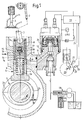
- a hydraulic linkage 4 is switched on according to FIG. 1 between a cam 2 and a push rod 3.
- This hydraulic linkage 4 consists of the valve tappet 5, which at the same time takes over the function of a cylinder and a piston 6 which is movable in the axial direction, but its movement can be limited by first and second stops 7a and 7b.
- a compensating piston 8 is arranged, which transmits the movement of the piston 6 to the push rod 3.
- a compression spring 9 is switched on, which holds the piston 6 in the starting position.
- the cylinder space 10 enclosed by the valve tappet 5 and the piston 6 is connected to a solenoid valve 12 via a short-held connecting line 11, the connecting line 11 again being in communication with an engine lubricating oil circuit 13 when the solenoid valve 12 is open.
- the compensating piston 8 can be provided in the valve train as a hydraulic valve lash adjuster, which has a bore 14 which allows a cylinder space 15 between the piston 6 and the compensating piston 8 to be connected to the engine lubricating oil circuit 13 by means of a compensating line 16.
- a spring 17 loaded valve 18 which can be designed as a ball, the bore 14 is closed, or oil can be sucked in via the compensating line 16.
- the cam 2 is provided with a first and a second elevation 2a and 2b, the first elevation 2a bringing about the normal opening of the exhaust valve 1 during the push-out phase and the second elevation 2b opening the exhaust valve 1 in the compression phase with the engine - Brake operation is reserved.
- the control of the solenoid valve 12 is carried out by a control device 19, which operates electronically and which receives its signals to be processed from at least one transmitter, which is designed as a sensor 20, and works on an inductive basis.
- a control device 19 which operates electronically and which receives its signals to be processed from at least one transmitter, which is designed as a sensor 20, and works on an inductive basis.
- two or more sensors 20 and 21 can also be provided, which are arranged offset by a certain angle on the periphery of a flywheel 23 provided with ring gear 22.
- a camshaft gear can also be provided.
- the voltage pulses coming from the sensors 20 and 21 are processed in the control device 19 in such a way that the position of the cam 2 and its second elevation 2b are recognized and the angular ranges ⁇ 1 to ⁇ 6 described below in FIG. 2 are determined.
- the pulses processed in the control unit 19 are fed to a solenoid 24 of the solenoid valve.
- a fast solenoid valve 12 is assigned to each exhaust valve 1.
- the control unit 19 is able to determine the position of all the cams via the sensors 20 or 21.
- the control unit 19 is activated by a switch 25, which switch 25 can be one or two stages, so that the Motor brake is actuated in stages.
- a throttle not shown here
- the solenoid valve 12 is also actuated in order to open the exhaust valve 1 even during the compression phase to such an extent that push-out work is carried out in order to reduce the braking power to increase.
- the order of the graduated engine brake can of course also be reversed in adaptation to the desired braking power.
- the solenoid valve 12 When the engine is running, the solenoid valve 12 is permanently open, and the electronic control is thus completely inactive. During the extension phase, the first elevation 2a of the cam 2 lifts the valve lifter 5. Since the solenoid valve 12 is open, no pressure can be built up in the cylinder space 10. Only when the first stop 7a in the valve tappet 5 hits the piston 6 is the movement of the valve tappet 5 transferred to the piston 6 and, via the second stop 7b, to the push rod 3, which opens the outlet valve 1. With further rotation of the cam 2, the exhaust valve 1 closes again.
- the switch 25 can also be carried out in two stages, so that in a first stage only the normal exhaust brake is actuated and in a second stage the hydropneumatic brake or vice versa. The braking power can thus be graded.
- FIG. 2 shows a cam according to the invention with a second elevation.
- Cam 2 is divided into sectors with angles ⁇ 1 to ⁇ 6.
- a sector with angle ⁇ 1 serves to open the valve in the push-out phase.
- a sector with angle ⁇ 2 fulfills the task.
- a sector with angles .alpha.3 gives the solenoid valve 12 (FIG. 1) time to close in engine braking mode.
- the second elevation 2b begins in a sector with an angle ⁇ 4.
- the solenoid valve 12 (FIG. 1) is closed and the outlet valve 1 opens in the compression phase, so that braking work can be carried out in addition to the extension phase.
- a sector with angle ⁇ 5 gives the solenoid valve time to open.
- a subsequent sector with angle ⁇ 6 serves to push the oil out of the cylinder space 10.
- valve opening curve of the exhaust valve is labeled A.
- the exhaust valve opens between bottom dead center UT and a gas exchange GOT.
- GOT gas exchange
- the second elevation 2b of the cam 2 also opens the outlet valve 1 between the bottom dead center UT and an ignition ZOT, so that in this phase the throttle effect of the outlet valve 1, which is only slightly opened further push-out work is done and compression work is destroyed, and the braking power is increased in addition to the braking power of the known exhaust brake.
Landscapes
- Engineering & Computer Science (AREA)
- Mechanical Engineering (AREA)
- General Engineering & Computer Science (AREA)
- Valve Device For Special Equipments (AREA)
- Output Control And Ontrol Of Special Type Engine (AREA)
- Valves And Accessory Devices For Braking Systems (AREA)
Priority Applications (1)
| Application Number | Priority Date | Filing Date | Title |
|---|---|---|---|
| AT91100566T ATE96500T1 (de) | 1990-03-08 | 1991-01-18 | Motorbremse fuer luftverdichtende brennkraftmaschinen. |
Applications Claiming Priority (2)
| Application Number | Priority Date | Filing Date | Title |
|---|---|---|---|
| DE4007287 | 1990-03-08 | ||
| DE4007287A DE4007287A1 (de) | 1990-03-08 | 1990-03-08 | Motorbremse fuer luftverdichtende brennkraftmaschine |
Publications (2)
| Publication Number | Publication Date |
|---|---|
| EP0446577A1 EP0446577A1 (de) | 1991-09-18 |
| EP0446577B1 true EP0446577B1 (de) | 1993-10-27 |
Family
ID=6401676
Family Applications (1)
| Application Number | Title | Priority Date | Filing Date |
|---|---|---|---|
| EP91100566A Expired - Lifetime EP0446577B1 (de) | 1990-03-08 | 1991-01-18 | Motorbremse für luftverdichtende Brennkraftmaschinen |
Country Status (6)
| Country | Link |
|---|---|
| US (1) | US5086738A (ref) |
| EP (1) | EP0446577B1 (ref) |
| JP (1) | JPH04224215A (ref) |
| AT (1) | ATE96500T1 (ref) |
| DE (2) | DE4007287A1 (ref) |
| RU (1) | RU2033548C1 (ref) |
Families Citing this family (35)
| Publication number | Priority date | Publication date | Assignee | Title |
|---|---|---|---|---|
| IT1255447B (it) * | 1991-11-08 | 1995-10-31 | Iveco Fiat | Motore provvisto di un dispositivo di frenatura continua, particolarmente per un veicolo industriale. |
| DE4209775A1 (de) * | 1992-03-26 | 1993-09-30 | Man Nutzfahrzeuge Ag | Vorrichtung zur Steuerung eines Auslaßventils im Motor-Bremsbetrieb |
| US5251590A (en) * | 1992-06-01 | 1993-10-12 | Caterpillar Inc. | Method and apparatus for starting an engine utilizing unit valve actuation |
| US5255650A (en) * | 1992-06-01 | 1993-10-26 | Caterpillar Inc. | Engine braking utilizing unit valve actuation |
| GB9312389D0 (en) * | 1993-06-16 | 1993-07-28 | Hersham Valves Ltd | Exhaust brake |
| US5647318A (en) | 1994-07-29 | 1997-07-15 | Caterpillar Inc. | Engine compression braking apparatus and method |
| US5540201A (en) | 1994-07-29 | 1996-07-30 | Caterpillar Inc. | Engine compression braking apparatus and method |
| US5526784A (en) | 1994-08-04 | 1996-06-18 | Caterpillar Inc. | Simultaneous exhaust valve opening braking system |
| US5713331A (en) * | 1994-12-21 | 1998-02-03 | Mannesmann Rexroth Gmbh | Injection and exhaust-brake system for an internal combustion engine having several cylinders |
| ES2116123T3 (es) * | 1995-04-04 | 1998-07-01 | Steyr Nutzfahrzeuge | Procedimiento para el frenado por motor con un motor de combustion interna de cuatro tiempos. |
| EP0843779B1 (en) * | 1995-08-08 | 2001-02-28 | Diesel Engine Retarders, Inc. | A compresssion release braking system for an internal combustion engine |
| DE19538729C2 (de) * | 1995-10-18 | 1998-01-15 | Daimler Benz Ag | Motorbremsvorrichtung für eine Brennkraftmaschine |
| WO1998012434A1 (de) * | 1996-09-19 | 1998-03-26 | Robert Bosch Gmbh | Kolbenpumpe |
| US5787858A (en) * | 1996-10-07 | 1998-08-04 | Meneely; Vincent Allan | Engine brake with controlled valve closing |
| RU2135785C1 (ru) * | 1998-02-12 | 1999-08-27 | Военный автомобильный институт | Комбинированный моторный замедлитель грузовых автомобилей |
| US6085721A (en) * | 1998-04-03 | 2000-07-11 | Diesel Engine Retarders, Inc. | Bar engine brake |
| US6092496A (en) * | 1998-09-04 | 2000-07-25 | Caterpillar Inc. | Cold starting method for diesel engine with variable valve timing |
| CN1327110C (zh) | 1999-08-23 | 2007-07-18 | 丰田自动车株式会社 | 发动机的阀特性控制装置 |
| US6205975B1 (en) | 1999-12-16 | 2001-03-27 | Caterpillar Inc. | Method and apparatus for controlling the actuation of a compression brake |
| RU2187660C2 (ru) * | 2000-04-10 | 2002-08-20 | Военный автомобильный институт | Моторный замедлитель грузовых автомобилей |
| RU2186994C2 (ru) * | 2000-08-15 | 2002-08-10 | Военный автомобильный институт | Моторный замедлитель для двигателя внутреннего сгорания |
| US6470851B1 (en) | 2000-10-30 | 2002-10-29 | Caterpillar Inc | Method and apparatus of controlling the actuation of a compression brake |
| SE520346C2 (sv) * | 2000-11-27 | 2003-07-01 | Scania Cv Ab | Förbränningsmotor som innefattar en motorbromsfunktion |
| RU2293864C2 (ru) * | 2001-09-05 | 2007-02-20 | Военный автомобильный институт | Комбинированный моторный замедлитель грузовых автомобилей |
| RU2289710C2 (ru) * | 2001-09-13 | 2006-12-20 | Военный автомобильный институт | Компрессионный тормоз для двигателей внутреннего сгорания грузовых автомобилей |
| WO2003074855A2 (en) | 2002-03-04 | 2003-09-12 | Jenara Enterprises Ltd. | Apparatus and method for retarding an engine with an exhaust brake and a compression release brake |
| US6925976B2 (en) * | 2003-03-06 | 2005-08-09 | Jenara Enterprises Ltd. | Modal variable valve actuation system for internal combustion engine and method for operating the same |
| DE102004048072A1 (de) * | 2004-10-02 | 2006-04-13 | Ina-Schaeffler Kg | Variabler Ventiltrieb einer Brennkraftmaschine |
| AT500958B1 (de) * | 2004-10-18 | 2006-10-15 | Avl List Gmbh | Brennkraftmaschine mit einer abgas-motorbremse |
| US9067489B2 (en) * | 2007-10-09 | 2015-06-30 | Toyota Motor Engineering & Manufacturing North America, Inc. | System and method of preventing inadvertent check engine telltale |
| DE102008012907B4 (de) | 2008-03-06 | 2025-02-13 | Mercedes-Benz Group AG | Verfahren zum Gewinnen von Energie aus einem Abgasstrom sowie Kraftfahrzeug |
| US7789065B2 (en) * | 2008-07-09 | 2010-09-07 | Zhou Yang | Engine braking apparatus with mechanical linkage and lash adjustment |
| US20100037854A1 (en) * | 2008-08-18 | 2010-02-18 | Zhou Yang | Apparatus and method for engine braking |
| CN103321759B (zh) * | 2013-07-08 | 2016-01-13 | 潍柴动力股份有限公司 | 一种发动机、排气门制动模块及排气门制动液控系统 |
| CN107060943B (zh) * | 2017-06-07 | 2019-07-30 | 大连理工大学 | 一种低能耗制动开关 |
Family Cites Families (12)
| Publication number | Priority date | Publication date | Assignee | Title |
|---|---|---|---|---|
| FR2133288A5 (ref) * | 1971-04-15 | 1972-11-24 | Penhoet Loire Atlan Chan | |
| US3786792A (en) * | 1971-05-28 | 1974-01-22 | Mack Trucks | Variable valve timing system |
| DE2832542A1 (de) * | 1978-07-25 | 1980-02-07 | Maschf Augsburg Nuernberg Ag | Brennkraftmaschine mit motorbremse |
| US4333430A (en) * | 1979-06-15 | 1982-06-08 | Rosquist Von D | Engine brake |
| DE3026529A1 (de) * | 1980-07-12 | 1982-02-11 | M.A.N. Maschinenfabrik Augsburg-Nürnberg AG, 8500 Nürnberg | Motorbremse fuer eine verbrennungskraftmaschine |
| DE3300763A1 (de) * | 1983-01-12 | 1984-07-12 | M.A.N. Maschinenfabrik Augsburg-Nürnberg AG, 8500 Nürnberg | Hydraulische einrichtung zum betaetigen von gaswechselventilen |
| US4572114A (en) * | 1984-06-01 | 1986-02-25 | The Jacobs Manufacturing Company | Process and apparatus for compression release engine retarding producing two compression release events per cylinder per engine cycle |
| DE3428627A1 (de) * | 1984-08-03 | 1986-02-13 | Daimler-Benz Ag, 7000 Stuttgart | Viertakt-brennkraftmaschine |
| US4592319A (en) * | 1985-08-09 | 1986-06-03 | The Jacobs Manufacturing Company | Engine retarding method and apparatus |
| US4796573A (en) * | 1987-10-02 | 1989-01-10 | Allied-Signal Inc. | Hydraulic engine valve lifter assembly |
| DE3923371C1 (en) * | 1989-07-14 | 1990-06-13 | Daimler-Benz Aktiengesellschaft, 7000 Stuttgart, De | IC engine valve control system - can adjust exhaust valve lift to give throttle effect during engine braking |
| DE3939934A1 (de) * | 1989-12-02 | 1991-06-06 | Man Nutzfahrzeuge Ag | Ventilsteuerung fuer gaswechselventile von brennkraftmaschinen |
-
1990
- 1990-03-08 DE DE4007287A patent/DE4007287A1/de active Granted
-
1991
- 1991-01-18 DE DE91100566T patent/DE59100515D1/de not_active Expired - Fee Related
- 1991-01-18 AT AT91100566T patent/ATE96500T1/de not_active IP Right Cessation
- 1991-01-18 EP EP91100566A patent/EP0446577B1/de not_active Expired - Lifetime
- 1991-03-06 JP JP3040015A patent/JPH04224215A/ja active Pending
- 1991-03-07 RU SU914894715A patent/RU2033548C1/ru active
- 1991-03-08 US US07/667,050 patent/US5086738A/en not_active Expired - Fee Related
Also Published As
| Publication number | Publication date |
|---|---|
| DE59100515D1 (de) | 1993-12-02 |
| EP0446577A1 (de) | 1991-09-18 |
| US5086738A (en) | 1992-02-11 |
| ATE96500T1 (de) | 1993-11-15 |
| RU2033548C1 (ru) | 1995-04-20 |
| DE4007287A1 (de) | 1991-09-12 |
| JPH04224215A (ja) | 1992-08-13 |
| DE4007287C2 (ref) | 1992-02-20 |
Similar Documents
| Publication | Publication Date | Title |
|---|---|---|
| DE4007287C2 (ref) | ||
| DE69014894T2 (de) | Brennkraftmaschine mit solenoidkontrolle der ventile und akkumulator zur druckrückgewinnung. | |
| EP0432404A2 (de) | Ventilsteuerung für Gaswechselventile von Brennkraftmaschinen | |
| DE68904693T2 (de) | Vorrichtung zum umschalten der betriebsart der ventile in einer brennkraftmaschine. | |
| EP0584575B1 (de) | Brennkraftmaschine mit einer Vorrichtung zum Umschalten von einer Betriebsart auf eine andere Betriebsart. | |
| DE4111610C2 (de) | Vorrichtung zur Veränderung der Steuerzeiten eines Gaswechselventils | |
| DE60200671T2 (de) | Mechanische Dekompressions- und Vakuumsablasseinrichtung | |
| US7610881B2 (en) | Apparatus for an internal combustion engine | |
| DE102012205759A1 (de) | Ventilsystem | |
| DE10029261A1 (de) | Nockenwellenverschwenkeinrichtung | |
| DE102010026393A1 (de) | Kraftstoffpumpen-Antriebssystem | |
| DE69432362T2 (de) | Variables ventilverteilungssystem | |
| DE102008015137A1 (de) | Vorrichtung und Verfahen zum Betätigen mindestens eines Gaswechselventils einer Brennkraftmaschine | |
| DE60200525T2 (de) | Brennkraftmaschine mit variabler hydraulischer Ventilsteuerung | |
| DE19807351C2 (de) | Brennkraftmaschine mit innerer Verbrennung | |
| DE102004048288A1 (de) | Variabler Ventiltrieb einer Brennkraftmaschine | |
| EP1022444B1 (de) | Hydraulisch geregelte, zwangsgesteuerte Ventilhubbetätigung für einen Mehrventilzylinderkopf | |
| DE102006053703A1 (de) | Vorrichtung zur Steuerung von Gaswechselventilen von Brennkraftmaschinen | |
| EP1415070A1 (de) | Vorrichtung zur steuerung von gaswechselventilen | |
| DE102008049529B4 (de) | Brennkraftmaschine mit hydraulischem Ventilspielausgleich und innerer Abgasrückführung | |
| DE3817554C2 (ref) | ||
| DE102016215676A1 (de) | Variabler Ventiltrieb für eine Hubkolbenbrennkraftmaschine | |
| DE102014003466A1 (de) | Vorrichtung und Verfahren zur variablen Steuerung eines Ventils einer Brennkraftmaschine | |
| WO2023046753A1 (de) | Verfahren zum betreiben einer brennkraftmaschine sowie entsprechende brennkraftmaschine | |
| DE4427271A1 (de) | Ventiltrieb für ein nockenbetätigtes, schließfederbestücktes Hubventil |
Legal Events
| Date | Code | Title | Description |
|---|---|---|---|
| PUAI | Public reference made under article 153(3) epc to a published international application that has entered the european phase |
Free format text: ORIGINAL CODE: 0009012 |
|
| AK | Designated contracting states |
Kind code of ref document: A1 Designated state(s): AT DE FR GB IT NL SE |
|
| 17P | Request for examination filed |
Effective date: 19911029 |
|
| 17Q | First examination report despatched |
Effective date: 19921016 |
|
| ITF | It: translation for a ep patent filed | ||
| GRAA | (expected) grant |
Free format text: ORIGINAL CODE: 0009210 |
|
| AK | Designated contracting states |
Kind code of ref document: B1 Designated state(s): AT DE FR GB IT NL SE |
|
| REF | Corresponds to: |
Ref document number: 96500 Country of ref document: AT Date of ref document: 19931115 Kind code of ref document: T |
|
| REF | Corresponds to: |
Ref document number: 59100515 Country of ref document: DE Date of ref document: 19931202 |
|
| ET | Fr: translation filed | ||
| GBT | Gb: translation of ep patent filed (gb section 77(6)(a)/1977) |
Effective date: 19931207 |
|
| PLBE | No opposition filed within time limit |
Free format text: ORIGINAL CODE: 0009261 |
|
| STAA | Information on the status of an ep patent application or granted ep patent |
Free format text: STATUS: NO OPPOSITION FILED WITHIN TIME LIMIT |
|
| 26N | No opposition filed | ||
| EAL | Se: european patent in force in sweden |
Ref document number: 91100566.8 |
|
| PGFP | Annual fee paid to national office [announced via postgrant information from national office to epo] |
Ref country code: SE Payment date: 19961209 Year of fee payment: 7 |
|
| PGFP | Annual fee paid to national office [announced via postgrant information from national office to epo] |
Ref country code: GB Payment date: 19970109 Year of fee payment: 7 |
|
| PGFP | Annual fee paid to national office [announced via postgrant information from national office to epo] |
Ref country code: AT Payment date: 19970128 Year of fee payment: 7 |
|
| PGFP | Annual fee paid to national office [announced via postgrant information from national office to epo] |
Ref country code: NL Payment date: 19970130 Year of fee payment: 7 |
|
| PGFP | Annual fee paid to national office [announced via postgrant information from national office to epo] |
Ref country code: FR Payment date: 19970228 Year of fee payment: 7 |
|
| PGFP | Annual fee paid to national office [announced via postgrant information from national office to epo] |
Ref country code: DE Payment date: 19970311 Year of fee payment: 7 |
|
| PG25 | Lapsed in a contracting state [announced via postgrant information from national office to epo] |
Ref country code: GB Free format text: LAPSE BECAUSE OF NON-PAYMENT OF DUE FEES Effective date: 19980118 Ref country code: AT Free format text: LAPSE BECAUSE OF NON-PAYMENT OF DUE FEES Effective date: 19980118 |
|
| PG25 | Lapsed in a contracting state [announced via postgrant information from national office to epo] |
Ref country code: SE Free format text: LAPSE BECAUSE OF NON-PAYMENT OF DUE FEES Effective date: 19980119 |
|
| PG25 | Lapsed in a contracting state [announced via postgrant information from national office to epo] |
Ref country code: FR Free format text: THE PATENT HAS BEEN ANNULLED BY A DECISION OF A NATIONAL AUTHORITY Effective date: 19980131 |
|
| PG25 | Lapsed in a contracting state [announced via postgrant information from national office to epo] |
Ref country code: NL Free format text: LAPSE BECAUSE OF NON-PAYMENT OF DUE FEES Effective date: 19980801 |
|
| GBPC | Gb: european patent ceased through non-payment of renewal fee |
Effective date: 19980118 |
|
| NLV4 | Nl: lapsed or anulled due to non-payment of the annual fee |
Effective date: 19980801 |
|
| PG25 | Lapsed in a contracting state [announced via postgrant information from national office to epo] |
Ref country code: DE Free format text: LAPSE BECAUSE OF NON-PAYMENT OF DUE FEES Effective date: 19981001 |
|
| EUG | Se: european patent has lapsed |
Ref document number: 91100566.8 |
|
| REG | Reference to a national code |
Ref country code: FR Ref legal event code: ST |
|
| PG25 | Lapsed in a contracting state [announced via postgrant information from national office to epo] |
Ref country code: IT Free format text: LAPSE BECAUSE OF NON-PAYMENT OF DUE FEES Effective date: 20050118 |