EP0442089A2 - Système de freinage - Google Patents
Système de freinage Download PDFInfo
- Publication number
- EP0442089A2 EP0442089A2 EP19900124338 EP90124338A EP0442089A2 EP 0442089 A2 EP0442089 A2 EP 0442089A2 EP 19900124338 EP19900124338 EP 19900124338 EP 90124338 A EP90124338 A EP 90124338A EP 0442089 A2 EP0442089 A2 EP 0442089A2
- Authority
- EP
- European Patent Office
- Prior art keywords
- brake
- valve
- pressure
- feed
- circuit
- Prior art date
- Legal status (The legal status is an assumption and is not a legal conclusion. Google has not performed a legal analysis and makes no representation as to the accuracy of the status listed.)
- Withdrawn
Links
Images


Classifications
-
- B—PERFORMING OPERATIONS; TRANSPORTING
- B60—VEHICLES IN GENERAL
- B60T—VEHICLE BRAKE CONTROL SYSTEMS OR PARTS THEREOF; BRAKE CONTROL SYSTEMS OR PARTS THEREOF, IN GENERAL; ARRANGEMENT OF BRAKING ELEMENTS ON VEHICLES IN GENERAL; PORTABLE DEVICES FOR PREVENTING UNWANTED MOVEMENT OF VEHICLES; VEHICLE MODIFICATIONS TO FACILITATE COOLING OF BRAKES
- B60T8/00—Arrangements for adjusting wheel-braking force to meet varying vehicular or ground-surface conditions, e.g. limiting or varying distribution of braking force
- B60T8/32—Arrangements for adjusting wheel-braking force to meet varying vehicular or ground-surface conditions, e.g. limiting or varying distribution of braking force responsive to a speed condition, e.g. acceleration or deceleration
- B60T8/34—Arrangements for adjusting wheel-braking force to meet varying vehicular or ground-surface conditions, e.g. limiting or varying distribution of braking force responsive to a speed condition, e.g. acceleration or deceleration having a fluid pressure regulator responsive to a speed condition
- B60T8/48—Arrangements for adjusting wheel-braking force to meet varying vehicular or ground-surface conditions, e.g. limiting or varying distribution of braking force responsive to a speed condition, e.g. acceleration or deceleration having a fluid pressure regulator responsive to a speed condition connecting the brake actuator to an alternative or additional source of fluid pressure, e.g. traction control systems
-
- B—PERFORMING OPERATIONS; TRANSPORTING
- B60—VEHICLES IN GENERAL
- B60T—VEHICLE BRAKE CONTROL SYSTEMS OR PARTS THEREOF; BRAKE CONTROL SYSTEMS OR PARTS THEREOF, IN GENERAL; ARRANGEMENT OF BRAKING ELEMENTS ON VEHICLES IN GENERAL; PORTABLE DEVICES FOR PREVENTING UNWANTED MOVEMENT OF VEHICLES; VEHICLE MODIFICATIONS TO FACILITATE COOLING OF BRAKES
- B60T8/00—Arrangements for adjusting wheel-braking force to meet varying vehicular or ground-surface conditions, e.g. limiting or varying distribution of braking force
- B60T8/32—Arrangements for adjusting wheel-braking force to meet varying vehicular or ground-surface conditions, e.g. limiting or varying distribution of braking force responsive to a speed condition, e.g. acceleration or deceleration
- B60T8/34—Arrangements for adjusting wheel-braking force to meet varying vehicular or ground-surface conditions, e.g. limiting or varying distribution of braking force responsive to a speed condition, e.g. acceleration or deceleration having a fluid pressure regulator responsive to a speed condition
- B60T8/341—Systems characterised by their valves
-
- B—PERFORMING OPERATIONS; TRANSPORTING
- B60—VEHICLES IN GENERAL
- B60T—VEHICLE BRAKE CONTROL SYSTEMS OR PARTS THEREOF; BRAKE CONTROL SYSTEMS OR PARTS THEREOF, IN GENERAL; ARRANGEMENT OF BRAKING ELEMENTS ON VEHICLES IN GENERAL; PORTABLE DEVICES FOR PREVENTING UNWANTED MOVEMENT OF VEHICLES; VEHICLE MODIFICATIONS TO FACILITATE COOLING OF BRAKES
- B60T8/00—Arrangements for adjusting wheel-braking force to meet varying vehicular or ground-surface conditions, e.g. limiting or varying distribution of braking force
- B60T8/26—Arrangements for adjusting wheel-braking force to meet varying vehicular or ground-surface conditions, e.g. limiting or varying distribution of braking force characterised by producing differential braking between front and rear wheels
- B60T8/266—Arrangements for adjusting wheel-braking force to meet varying vehicular or ground-surface conditions, e.g. limiting or varying distribution of braking force characterised by producing differential braking between front and rear wheels using valves or actuators with external control means
- B60T8/268—Arrangements for adjusting wheel-braking force to meet varying vehicular or ground-surface conditions, e.g. limiting or varying distribution of braking force characterised by producing differential braking between front and rear wheels using valves or actuators with external control means using the valves of an ABS, ASR or ESP system
-
- B—PERFORMING OPERATIONS; TRANSPORTING
- B60—VEHICLES IN GENERAL
- B60T—VEHICLE BRAKE CONTROL SYSTEMS OR PARTS THEREOF; BRAKE CONTROL SYSTEMS OR PARTS THEREOF, IN GENERAL; ARRANGEMENT OF BRAKING ELEMENTS ON VEHICLES IN GENERAL; PORTABLE DEVICES FOR PREVENTING UNWANTED MOVEMENT OF VEHICLES; VEHICLE MODIFICATIONS TO FACILITATE COOLING OF BRAKES
- B60T8/00—Arrangements for adjusting wheel-braking force to meet varying vehicular or ground-surface conditions, e.g. limiting or varying distribution of braking force
- B60T8/32—Arrangements for adjusting wheel-braking force to meet varying vehicular or ground-surface conditions, e.g. limiting or varying distribution of braking force responsive to a speed condition, e.g. acceleration or deceleration
- B60T8/34—Arrangements for adjusting wheel-braking force to meet varying vehicular or ground-surface conditions, e.g. limiting or varying distribution of braking force responsive to a speed condition, e.g. acceleration or deceleration having a fluid pressure regulator responsive to a speed condition
- B60T8/38—Arrangements for adjusting wheel-braking force to meet varying vehicular or ground-surface conditions, e.g. limiting or varying distribution of braking force responsive to a speed condition, e.g. acceleration or deceleration having a fluid pressure regulator responsive to a speed condition including valve means of the relay or driver controlled type
-
- B—PERFORMING OPERATIONS; TRANSPORTING
- B60—VEHICLES IN GENERAL
- B60T—VEHICLE BRAKE CONTROL SYSTEMS OR PARTS THEREOF; BRAKE CONTROL SYSTEMS OR PARTS THEREOF, IN GENERAL; ARRANGEMENT OF BRAKING ELEMENTS ON VEHICLES IN GENERAL; PORTABLE DEVICES FOR PREVENTING UNWANTED MOVEMENT OF VEHICLES; VEHICLE MODIFICATIONS TO FACILITATE COOLING OF BRAKES
- B60T8/00—Arrangements for adjusting wheel-braking force to meet varying vehicular or ground-surface conditions, e.g. limiting or varying distribution of braking force
- B60T8/32—Arrangements for adjusting wheel-braking force to meet varying vehicular or ground-surface conditions, e.g. limiting or varying distribution of braking force responsive to a speed condition, e.g. acceleration or deceleration
- B60T8/34—Arrangements for adjusting wheel-braking force to meet varying vehicular or ground-surface conditions, e.g. limiting or varying distribution of braking force responsive to a speed condition, e.g. acceleration or deceleration having a fluid pressure regulator responsive to a speed condition
- B60T8/40—Arrangements for adjusting wheel-braking force to meet varying vehicular or ground-surface conditions, e.g. limiting or varying distribution of braking force responsive to a speed condition, e.g. acceleration or deceleration having a fluid pressure regulator responsive to a speed condition comprising an additional fluid circuit including fluid pressurising means for modifying the pressure of the braking fluid, e.g. including wheel driven pumps for detecting a speed condition, or pumps which are controlled by means independent of the braking system
- B60T8/4072—Systems in which a driver input signal is used as a control signal for the additional fluid circuit which is normally used for braking
-
- B—PERFORMING OPERATIONS; TRANSPORTING
- B60—VEHICLES IN GENERAL
- B60T—VEHICLE BRAKE CONTROL SYSTEMS OR PARTS THEREOF; BRAKE CONTROL SYSTEMS OR PARTS THEREOF, IN GENERAL; ARRANGEMENT OF BRAKING ELEMENTS ON VEHICLES IN GENERAL; PORTABLE DEVICES FOR PREVENTING UNWANTED MOVEMENT OF VEHICLES; VEHICLE MODIFICATIONS TO FACILITATE COOLING OF BRAKES
- B60T8/00—Arrangements for adjusting wheel-braking force to meet varying vehicular or ground-surface conditions, e.g. limiting or varying distribution of braking force
- B60T8/32—Arrangements for adjusting wheel-braking force to meet varying vehicular or ground-surface conditions, e.g. limiting or varying distribution of braking force responsive to a speed condition, e.g. acceleration or deceleration
- B60T8/34—Arrangements for adjusting wheel-braking force to meet varying vehicular or ground-surface conditions, e.g. limiting or varying distribution of braking force responsive to a speed condition, e.g. acceleration or deceleration having a fluid pressure regulator responsive to a speed condition
- B60T8/44—Arrangements for adjusting wheel-braking force to meet varying vehicular or ground-surface conditions, e.g. limiting or varying distribution of braking force responsive to a speed condition, e.g. acceleration or deceleration having a fluid pressure regulator responsive to a speed condition co-operating with a power-assist booster means associated with a master cylinder for controlling the release and reapplication of brake pressure through an interaction with the power assist device, i.e. open systems
- B60T8/445—Arrangements for adjusting wheel-braking force to meet varying vehicular or ground-surface conditions, e.g. limiting or varying distribution of braking force responsive to a speed condition, e.g. acceleration or deceleration having a fluid pressure regulator responsive to a speed condition co-operating with a power-assist booster means associated with a master cylinder for controlling the release and reapplication of brake pressure through an interaction with the power assist device, i.e. open systems replenishing the released brake fluid volume into the brake piping
-
- B—PERFORMING OPERATIONS; TRANSPORTING
- B60—VEHICLES IN GENERAL
- B60T—VEHICLE BRAKE CONTROL SYSTEMS OR PARTS THEREOF; BRAKE CONTROL SYSTEMS OR PARTS THEREOF, IN GENERAL; ARRANGEMENT OF BRAKING ELEMENTS ON VEHICLES IN GENERAL; PORTABLE DEVICES FOR PREVENTING UNWANTED MOVEMENT OF VEHICLES; VEHICLE MODIFICATIONS TO FACILITATE COOLING OF BRAKES
- B60T8/00—Arrangements for adjusting wheel-braking force to meet varying vehicular or ground-surface conditions, e.g. limiting or varying distribution of braking force
- B60T8/32—Arrangements for adjusting wheel-braking force to meet varying vehicular or ground-surface conditions, e.g. limiting or varying distribution of braking force responsive to a speed condition, e.g. acceleration or deceleration
- B60T8/34—Arrangements for adjusting wheel-braking force to meet varying vehicular or ground-surface conditions, e.g. limiting or varying distribution of braking force responsive to a speed condition, e.g. acceleration or deceleration having a fluid pressure regulator responsive to a speed condition
- B60T8/48—Arrangements for adjusting wheel-braking force to meet varying vehicular or ground-surface conditions, e.g. limiting or varying distribution of braking force responsive to a speed condition, e.g. acceleration or deceleration having a fluid pressure regulator responsive to a speed condition connecting the brake actuator to an alternative or additional source of fluid pressure, e.g. traction control systems
- B60T8/4809—Traction control, stability control, using both the wheel brakes and other automatic braking systems
- B60T8/4827—Traction control, stability control, using both the wheel brakes and other automatic braking systems in hydraulic brake systems
-
- B—PERFORMING OPERATIONS; TRANSPORTING
- B60—VEHICLES IN GENERAL
- B60T—VEHICLE BRAKE CONTROL SYSTEMS OR PARTS THEREOF; BRAKE CONTROL SYSTEMS OR PARTS THEREOF, IN GENERAL; ARRANGEMENT OF BRAKING ELEMENTS ON VEHICLES IN GENERAL; PORTABLE DEVICES FOR PREVENTING UNWANTED MOVEMENT OF VEHICLES; VEHICLE MODIFICATIONS TO FACILITATE COOLING OF BRAKES
- B60T8/00—Arrangements for adjusting wheel-braking force to meet varying vehicular or ground-surface conditions, e.g. limiting or varying distribution of braking force
- B60T8/32—Arrangements for adjusting wheel-braking force to meet varying vehicular or ground-surface conditions, e.g. limiting or varying distribution of braking force responsive to a speed condition, e.g. acceleration or deceleration
- B60T8/88—Arrangements for adjusting wheel-braking force to meet varying vehicular or ground-surface conditions, e.g. limiting or varying distribution of braking force responsive to a speed condition, e.g. acceleration or deceleration with failure responsive means, i.e. means for detecting and indicating faulty operation of the speed responsive control means
- B60T8/90—Arrangements for adjusting wheel-braking force to meet varying vehicular or ground-surface conditions, e.g. limiting or varying distribution of braking force responsive to a speed condition, e.g. acceleration or deceleration with failure responsive means, i.e. means for detecting and indicating faulty operation of the speed responsive control means using a simulated speed signal to test speed responsive control means
-
- Y—GENERAL TAGGING OF NEW TECHNOLOGICAL DEVELOPMENTS; GENERAL TAGGING OF CROSS-SECTIONAL TECHNOLOGIES SPANNING OVER SEVERAL SECTIONS OF THE IPC; TECHNICAL SUBJECTS COVERED BY FORMER USPC CROSS-REFERENCE ART COLLECTIONS [XRACs] AND DIGESTS
- Y10—TECHNICAL SUBJECTS COVERED BY FORMER USPC
- Y10S—TECHNICAL SUBJECTS COVERED BY FORMER USPC CROSS-REFERENCE ART COLLECTIONS [XRACs] AND DIGESTS
- Y10S303/00—Fluid-pressure and analogous brake systems
- Y10S303/02—Brake control by pressure comparison
- Y10S303/03—Electrical pressure sensor
- Y10S303/04—Pressure signal used in electrical speed controlled braking circuit
Definitions
- the invention relates to a brake system according to the preamble of claim 1.
- Brake systems of this type having a master brake cylinder, via which brake circuits, in particular a brake circuit for the front wheels and a brake circuit for the rear wheels, are supplied with brake fluid, are well known. The same also applies to a corresponding shut-off valve arrangement for anti-lock control.
- the brake design for vehicle axles has to take into account in particular the dynamic axle loads and their changes. Ideally, the braking force is always proportional to the braking and the dynamic axle load. However, this "ideal" braking force distribution changes very strongly with braking.
- the wheels of the rear axle when the vehicle is braked to 0.8g, the wheels of the rear axle must not lock in front of those on the front axle, because if the wheels of the rear axle lock first, a vehicle hurls, while if the front axle locks at first it loses steering ability, but remains relatively stable.
- the aim of the present invention is to realize a high pressure control in all wheel brake cylinders with a functional anti-lock braking system and nevertheless to keep the motor vehicle manageable and stable in the event of a failure of the anti-lock braking system.
- an I. and II. Brake circuit after the shut-off valves is connected to a feed system which has devices for feeding brake fluid of different pressures into the I and II. Brake circuit.
- This will increase the brake pressure of individual circles or wheels in the normal braking situation, i.e. H. without anti-lock control.
- the feeding of the different pressures into the 1st and 2nd brake circuits is controlled by the driver and in such a way that only a relative pressure increase takes place between the rear axle circuit compared to the front axle circuit. In this way, for example, the braking devices of the rear axle that have been severely braked so far are increasingly included in a braking operation.
- feed valves are provided between the first and second brake circuits and the feed system, via which the connection of the feed system is regulated.
- Check valves follow the feed valves for the 1st brake circuit, which prevent fluid from the 1st brake circuit from being consumed by additional volumes and by leaks in the feed system. In this way, they contribute significantly to security. Instead of these check valves, corresponding solenoid valves with a check position can also be provided.
- a delivery device for the additional brake fluid from the feed system into the 1st or 2nd brake circuit a self-priming pump is provided, and if the volume flow is not sufficient, an additional memory is assigned to it. According to the invention, it can be both a single-circuit and a double-circuit pump. As a rule, this pump is operated separately by an electric motor. It can also be designed as a tandem pump or flange pump.
- the pump is connected via a line directly to the feed valve of the second brake circuit, while the feed pressure for the feed valves of the first brake circuit can be adjusted via pressure limiting valves.
- the 1st or 2nd brake circuit it is usually a black-and-white brake circuit division, the 2nd brake circuit being the wheel brake systems of the rear axle and the 1st brake circuit being the wheel brake systems of the front axle with brake fluid provided.
- the supply can also be reversed.
- the pressure relief valves are essential in the present case. These pressure limiting valves are used to control the feed into the 1st brake circuit so that it takes place as a function of a brake pressure in the 2nd brake circuit. For this reason, a pressure relief valve is also provided with two hydraulically actuated surfaces of the same size on its valve body, one surface being preferably connected to the second brake circuit near the master brake cylinder. In the case of the other pressure relief valve, the pressurized areas of the valve body are of different sizes, the smaller area being connected to the delivery pressure of the pump. The front axle feed pressure that prevails between the pressure relief valves is used to counteract these pressures for both the first and the second valve.
- the pressure relief valve switches through and clears the way for the brake fluid back to a return line or the corresponding reservoir.
- the first pressure limiting valve opens the feed line from the pump to the first brake circuit when a relatively higher pressure is built up in front of the smaller area of the valve body. If the excessive pressure on the smaller surface outweighs the holding pressure on the larger surface, the valve opens and limits the feed pressure for the 2nd brake circuit.
- the counter pressure depends on the brake pressure in the second brake circuit, there is always only a relative increase in the pressure in one brake circuit in relation to the pressure in the other brake circuit. The infeed system can never initiate braking against the driver's will, as is possible with many systems that are independent of brake pressure.
- a possibly provided traction control system also takes place via the feed system.
- a separate control of each wheel is provided for the II. Brake circuit, in which the corresponding control valves for each wheel only follow the corresponding feed valve.
- the brake fluid the above-mentioned pump naturally provides for traction control, the feed valves being open in the case of traction control.
- the first brake circuit is assigned the pressure relief valve with two hydraulically actuated surfaces of the same size. This pressure relief valve is connected to the 1st brake circuit near the master brake cylinder. If the pressure in this first brake circuit increases, the pressure relief valve only switches over when the feed pressure is increased.
- the second pressure relief valve is coupled on the one hand to the II. Brake circuit near the brake booster and on the other hand to the feed line. However, the pressure in the feed line acts on the smaller area, so that here the feed pressure can be increased significantly before the pressure relief valve switches over.
- the actual feed valve between the pump and the II. Brake circuit is missing. Instead, a feed and shut-off valve is provided, which makes it easier to regulate and coordinate the feed system and the second brake circuit.
- a throttle which is upstream of this feed and shut-off valve, limits the pressure build-up gradient in the downstream wheel brake cylinders when switching over to an electrical or electronic brake force distribution.
- the present brake system can work with both a three and a four-channel anti-lock braking system.
- This four-channel anti-lock braking system is also intended to be encompassed by the present inventive concept.
- Another possibility of braking force distribution is not to leave the pressure absorption and control to the corresponding pressure limiting valves, but to provide a control unit for this purpose.
- Pressure is recorded in both the 1st and 2nd brake circuits and in the feed system.
- the pedal travel is also monitored.
- the control unit then takes over the regulation of all valves and also the motor of the feed system.
- the pressure in the two brake circuits is compared with one another in the control unit and regulated using an ideal distribution.
- the regulation then takes place by feeding additional brake fluid through the feed system into the corresponding brake circuit. For this reason, both brake circuits are connected to the feed system via a corresponding feed valve. Further valves for regulating the feed are of course provided.
- the control unit also takes over the control of an anti-lock case, the corresponding valves being blocked and other valves being opened for pressure release.
- An important advantage of the arrangement with the control unit is that the zero position of the pressure sensors can be corrected when there is no braking. This is done automatically via the control unit by operating the individual valves.
- a test cycle is also provided for the state of ventilation of the rear axle when the vehicle is stationary.
- the second brake circuit for the rear axle is pressurized and the time which is required to overcome a specific pressure build-up or the difference between two pressure values is determined. This can be used to calculate a time that should not be exceeded when the pressure builds up if the ventilation status is correct.
- the traction control is also carried out via the feed system in accordance with the known hydraulic multiplex method.
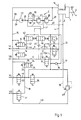
- a brake system has an I. and a II. Brake circuit. Both brake circuits open from a corresponding master brake cylinder 1, the detailed design of which is generally known for two brake circuits.
- the master brake cylinder 1 is acted upon by a piston rod 2 with brake pressure which is transmitted from a driver's foot by a brake pedal 3.
- the left and right front wheels or their wheel brake cylinders are supplied with brake fluid via the first brake circuit. This is done via a common main line 4, which is divided into two branch lines 5 and 6.
- a shut-off valve 7 or 8 is switched on, by means of which the respective branch line 5 or 6 can be shut off from the main line 4.
- Both shut-off valves 7 and 8 can be bypassed by a bypass line 9 or 10, in each of which a check valve 11 or 12 is switched on.
- each branch line 5 or 6 is connected by a further drain valve 13 or 14 to a return line 15 to a reservoir 16.
- the II. Brake circuit also has a main line 17, which is divided into two branch lines 18 and 19. Before the division, a shut-off valve 20 is provided, through which the main line 17 can be blocked. In each branch line 18 and 19, a shut-off and selection valve 21 and 22 is also switched on, which, as described later, serves to control the traction control.
- both branch lines 18 and 19 have a connection via a connecting line 23 and a valve 24 to the return line 15. This valve 24 has a return position for reducing brake pressure and a check position 26.
- An infeed system E is assigned to both brake circuits I and II.
- this feed system E has a single-circuit pump, which is preferably designed to be self-priming. However, if the volume flow is not sufficient, an additional one should be added Memory initiation may be provided.
- the pump is a separate pump operated by an electric motor, which can also be a tandem or flange pump.
- This pump 27 conveys brake fluid in the feed system E. This brake fluid is taken from the reservoir 16, a pump check valve 29 being switched on in the corresponding connection line 28.
- the brake fluid is conveyed through a further pump check valve 30, after which a line 31 branches off, which is connected to the main line 17 of the second brake circuit after the shut-off valve 20.
- Both pump check valves 29, 30 are integrated elements of the pump 27.
- a feed valve 32 is also switched on in line 31, via which line 31 can be closed.
- a bypass 33 with a corresponding check valve 34 is in turn provided for this feed valve 32.
- a further line 35 leads after the check valve 30 through a shut-off valve 36 to a pressure limiting valve 37.
- This pressure limiting valve 37 is followed by a second pressure limiting valve 38 which leads to the return line 15 via a connecting line 39.
- a feed line 41 which branches off and is connected to a branch line 42 via a feed valve 43 and a check valve 44 following it with the branch line 5 to the left front wheel.
- the return line 15 also has a connection 48 to the line 31, namely after the feed valve 32.
- a differential pressure relief valve 49 is used as a pressurized valve, which has a connection 50 to the main line 17 of the II.
- the shut-off valve 20 is normally switched to the locked position, both with normal braking and with an anti-lock or traction control system. It only assumes its open position when the servo pressure fails, which can happen, for example, when the pump 27 fails. Braking the wheels of the rear axle via the master brake cylinder is always possible. H. in emergency situations there is a full brake fluid reserve for the 2nd brake circuit. The possibility of suction for the wheel brake cylinders of the left and right rear wheels ensures the check position of the drain valve 24.
- brake circuit I or II fails, the other brake circuit remains intact while the supply system is switched off.
- the braking force distribution is essentially controlled via the pressure relief valves 37 and 38, respectively.
- the pressure relief valve 37 is provided with two differently sized, hydraulically loaded surfaces, as indicated in FIG. 2.
- a corresponding valve body 51 is held in the position shown under the pressure of a helical spring 52.
- the pressure of the helical spring is supported by a feed pressure P E , which prevails in the feed line 41.
- the valve body 51 has a diameter d2, which is larger than the diameter d1 of the line 35. In this line, the servo pressure P servo is present . However, the line 35 is closed by the valve body 51 and thus separated from the feed line. To open this pressure relief valve, the pressure P servo must be greater than the holding pressure P E ⁇
- the pressure relief valve following the pressure relief valve 37 38 has on the one hand the connection to the feed line 41, into which the feed pressure P E is effective.
- a valve ball 53 Via a further valve body 51a with the diameter d2, a valve ball 53 is pressed against the opening of the feed line 41, the corresponding effective valve seat having a diameter of d3.
- d3 is equal to d2.
- the closing force of the valve body 51a is maintained on the one hand by a coil spring 54 and on the other hand by the pressure detection via the connection 40 to the master brake cylinder 1.
- the brake system according to FIG. 1 also refers to a 3-channel anti-lock braking system with black and white brake circuit division.
- the same configuration can be used for a 4-channel anti-lock braking system and can be implemented without fundamental differences and major changes.
- shut-off valve 20 If, for certain reasons, a normally open 2/2 solenoid valve is provided for the shut-off valve 20, the feed valve 32 is closed in the initial position (de-energized). The shut-off valve 20 must now be switched in front of the feed valve 32 each time braking, since otherwise a clear pedal reaction would occur and the master cylinder piston would be pushed back. This could damage the central valve of the master brake cylinder. The pressure in the wheel brake cylinders would also rise suddenly, which would reduce driving comfort and also provoke frequent anti-lock control. The shut-off valve 20 must switch quickly when the brake is actuated in order to hold a sufficient amount of fluid in the master brake cylinder.
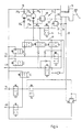
- FIG. 4 The embodiment of a further brake system according to Figure 4 differs from that of Figure 1 in particular by the design of the feed system E1.
- a dual-circuit pump 27a is provided for this feed system E 1.
- Corresponding pump check valves 29a and 29b connect the pump 27a to the return line 15.
- the pump check valves 30a and 30b are also connected downstream of the pump 27a.
- the pump check valves 29a, 29b and 30a, 30b are integral parts of the respective pump.
- the line 35a connects one pump circuit via the shut-off valve 36 to the pressure limiting valve 37.
- this pressure limiting valve is connected to the return line 15 as a pressure-controlled valve via line 55.
- the feed for the front axle brake circuit is regulated by the second circuit of the pump 27a via line 35b.
- This line is connected to the return line 15 by the pressure relief valve 38.
- this pressure relief valve 38 also has a connection 57 to the 1st brake circuit.
- a desired pressure difference between the I. and II. Brake circuit is in turn ensured by the pressure relief valve 37, which according to FIG. 2 has two surfaces which can be pressurized differently.
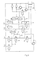
- FIG. 5 shows a further exemplary embodiment of a brake system according to the invention, in which case the feed valve 32 is replaced by a feed and shut-off valve 58.
- This combined valve 58 ensures the successive valve functions that would otherwise have to take place in succession as described in FIG. 1. In the position shown, the valve 58 blocks the line 31, while permitting the passage of brake fluid from the master cylinder 1 to the left and right rear wheels.
- valve 58 If the valve 58 is switched over, the main line 17 is blocked, but the feed line 31 is connected to the corresponding branch lines 18 and 19, respectively. Between line 31 and main line 17, valve 58 surrounds a further bypass 59, which is equipped with a check valve 60. It should possibly be ensured that the drain valve 24 can only be actuated when the combination valve 58 is switched. This can be done, for example, by a corresponding switch or a relay or the like.
- a throttle 61 is provided in line 31. This throttle limits the pressure build-up gradient in the wheel brake cylinders of the left and right rear wheels when switching to the feed mode to increase the rear axle brake pressure.
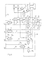
- FIG. 6 again shows an exemplary embodiment of an electrical or electronic brake force distribution according to the invention, specifically in a 4-channel anti-lock braking system.
- the brake circuit division is also black and white.
- a separate shut-off valve 20a or 20b is provided for both the left and the right rear wheel.
- each branch line 18 or 19 between the respective wheel brake cylinder and the shut-off valve 20a or 20b has a connection line 23a or 23b to the return line 15, the drain valves 24a or 24b switched on there being normal, conventional shut-off valves.
- the feed system E 1 corresponds to that of Figure 4.
- an additional line 62 is provided which connects the line 31 with the branch line 18.
- a further shut-off valve 63 is switched on, which is surrounded by a bypass 64 with a check valve 65.
- the pressure setting for traction control in this system serves a pressure relief valve 66 which is connected on the one hand to the bypass 64 and on the other hand to the return line 15. Through the pressure relief valve 66, there is a pressure comparison with the pressure in the main line 17 of the II. Brake circuit and with the pressure in the bypass line 64, a connection 67 via a check valve 68 to the feed line 31 being provided at the same time.
- a control unit 70 is provided, by means of which the entire brake system is controlled.
- This control unit includes a connection 71 to the wheel sensors (not shown in more detail), a further connection 72 to a servo pressure receptacle P Servo , a further connection 73 to a pressure receptacle P n for receiving the rear axle pressure, a connection 74 for receiving the front axle pressure P v and a connection 75 to accommodate the brake pedal travel S.
- the control unit controls the valves, only one output 76 being provided here for the sake of clarity.
- a motor 77 for the pump 27 is controlled via the control unit 70.
- Output 78 is provided for this purpose.
- a warning lamp 79 indicates faults in the brake system.
- the entire control unit has further connections 80 and 81 on the battery or ignition.
- the shut-off valves 7 and 8 are located in the 1st brake circuit for the wheels of the front axle.
- the check valves 11 and 12 already described above are also assigned to these shut-off valves.
- the feed valve 43 is provided in the present case between the pump 27 or a corresponding accumulator 82, but according to which the corresponding branch line 45 to the branch line 6 or the branch line 42 to the branch line 5 instead of the check valves 44 and 47 with additional solenoid valves 83 and 84 are occupied.
- These solenoid valves have a blocking position and a check position.
- shut-off valve 7 and 8 are switched to passage, while the drain valves 13 and 14 and the feed valve 43 and the solenoid valves 83 and 84 rest in the blocking position.
- pressure modulation in the wheel brake cylinders of the right and left front wheels is possible directly by actuating the master brake cylinder.
- shut-off valve 20 in the main line 17 of the II. Brake circuit to the wheels of the rear axle will be closed during partial braking. Also also the shut-off or selection valves 21 and 22.
- This feed system E2 differs from the one shown so far in that only one pressure relief valve 38 is present, since no differential pressure measurement is carried out in the feed system itself. The corresponding control takes over the control unit 70.
- the pressure modulation in the second brake circuit takes place in accordance with the ideal brake force distribution and controlled by the control unit 70. This compares the recorded pressure values P n and P v and modulates the brake pressure in the rear axle in accordance with a predetermined ideal curve.
- the feed valve 43, the shut-off valves 7 and 8 and the solenoid valves 83 and 84 are actuated by the control unit 70. This means that the shut-off valves 7 and 8 close while the Feed valve 43 opens.
- the two solenoid valves 83 and 84 go into the check position. Brake fluid can now be pumped from the pump 27 via the feed valve 43 and the solenoid valve 83 or 84 to the right or left front wheel brake cylinder. The pressure is adjusted via the feed valve 43.
- the pressure is then reduced via the drain valves 13 and 14, respectively, back into the return line 15.
- the corresponding wheel sensor detects this, so that, for example, the solenoid valve 84 then remains closed, while a pressure increase is carried out via the actuation time of the feed valve 43. If, for example, the wheel sensor of the left front wheel then additionally requests pressure build-up in the wheel brake cylinder of the left front wheel, the solenoid valve 84 is also opened.
- the line volume which is limited by the solenoid valves 83 and 84 and the feed valve 43, is approximately incompressible, so that no disturbance volume is stored.
- the solenoid valves 83 and 84 can nevertheless remain in the check position since the feed valve 43 is then closed.
- the pressure pick-up P Servo only shows the pressure which is present in the line between the feed valve 43 or the solenoid valve 83 and 84.
- the pressure pick-up P Servo shows the respective actual wheel pressure (with the solenoid valves 83 and 84 open).
- the control unit 70 does not permit a higher pressure P servo than that indicated by the pressure pickup P v , so that no higher pressure is fed into the front wheel brakes than specified by the driver.
- the characteristic curve does not become so large that the central valve in the master brake cylinder is damaged when the brake is released.
- additional pedal travel is permitted if necessary, be it by building up pressure in the main line 4 or the branch lines 5 and 6 via the shut-off valves 7 and 8 to the left and right front wheels or by volume displacement from the master brake cylinder into the reservoir 16 the shut-off valve 20 and the drain valve 24.
- a need arises especially when the relationship between the pedal travel and the front axle pressure P v required by the control unit 70 is not given.
- the curve of the required minimum pedal travel can also be made dependent on the increase in the coefficient of friction during the anti-lock control.
- the zero position of the pressure transducer P servo can be corrected by temporarily actuating the feed valve 43 and the solenoid valves 83 and 84 as long as there is no braking. This zero position also takes place automatically via the control unit.
- the state of bleeding of the 2nd brake circuit for the right and left rear wheel is monitored. This is done with a test cycle when the vehicle is stationary.
- the shut-off valve 20 is closed, the feed valve 32 is opened, the timing of the Pressure sensor P n is monitored.
- the time is determined which is required, for example, to increase the pressure to 20bar and then which time t2 is required to increase the pressure from 20bar to 50bar.
- the temperature of the liquid can be inferred from the time t2, so that a time tl can be calculated which is not exceeded if the venting state of the rear axle brake circuit is in order.
- This test cycle is based on the consideration that in the upper pressure range (above about 20 bar) the gradient is no longer dependent on the venting state.
- a circuit failure for example of the brake circuit I of the front axle, is recognized by the comparison between the brake pedal displacement sensor and the pressure sensor P v .
- a circuit failure is recognized via the activation time of the valves 7, 8, 43, 83 and 84.
- shut-off valve 20 is closed and entered through the feed system E2 brake fluid via line 31 and the feed valve 32 into the II. Brake circuit.
- shut-off or selection valves 21 and 22 are also open so that the brake fluid that is fed in can reach the wheel brake cylinders of the left and right rear wheels.
- the return takes place via the drain valve 24.
- the modulation takes place according to the known hydraulic multiplex method.
Landscapes
- Engineering & Computer Science (AREA)
- Transportation (AREA)
- Mechanical Engineering (AREA)
- Physics & Mathematics (AREA)
- Fluid Mechanics (AREA)
- Regulating Braking Force (AREA)
Applications Claiming Priority (2)
| Application Number | Priority Date | Filing Date | Title |
|---|---|---|---|
| DE4004270A DE4004270A1 (de) | 1990-02-13 | 1990-02-13 | Bremsanlage |
| DE4004270 | 1990-02-13 |
Publications (2)
| Publication Number | Publication Date |
|---|---|
| EP0442089A2 true EP0442089A2 (fr) | 1991-08-21 |
| EP0442089A3 EP0442089A3 (en) | 1992-05-06 |
Family
ID=6399971
Family Applications (1)
| Application Number | Title | Priority Date | Filing Date |
|---|---|---|---|
| EP19900124338 Withdrawn EP0442089A3 (en) | 1990-02-13 | 1990-12-15 | Brake system |
Country Status (5)
| Country | Link |
|---|---|
| US (1) | US5190358A (fr) |
| EP (1) | EP0442089A3 (fr) |
| JP (1) | JPH04215555A (fr) |
| KR (1) | KR910021321A (fr) |
| DE (1) | DE4004270A1 (fr) |
Cited By (2)
| Publication number | Priority date | Publication date | Assignee | Title |
|---|---|---|---|---|
| EP0566344A1 (fr) * | 1992-04-14 | 1993-10-20 | Lucas Industries Public Limited Company | Systèmes hydrauliques de freinage pour véhicules |
| GB2241295B (en) * | 1990-02-17 | 1994-04-06 | Bosch Gmbh Robert | A braking system for a motor vehicle |
Families Citing this family (16)
| Publication number | Priority date | Publication date | Assignee | Title |
|---|---|---|---|---|
| DE4029793C2 (de) * | 1990-09-20 | 1999-05-06 | Bosch Gmbh Robert | Hydraulische Fahrzeugbremsanlage |
| DE4106336A1 (de) * | 1991-02-28 | 1992-09-03 | Bosch Gmbh Robert | Hydraulische bremsanlage, insbesondere fuer kraftfahrzeuge |
| DE4208581A1 (de) * | 1992-03-18 | 1993-05-27 | Daimler Benz Ag | Bremsdruck-steuereinrichtung |
| DE4224971A1 (de) * | 1992-07-29 | 1994-02-03 | Teves Gmbh Alfred | Verfahren zur Erhöhung der Funktionssicherheit einer Bremsanlage mit elektronischer Regelung der Bremskraftverteilung |
| DE4227017C2 (de) * | 1992-08-14 | 2001-03-01 | Renk Ag | Bremsanlage |
| JPH06127360A (ja) * | 1992-10-13 | 1994-05-10 | Tokico Ltd | ブレーキ液圧制御装置 |
| DE4397414T1 (de) * | 1993-06-02 | 1996-05-09 | Yaskawa Denki Kitakyushu Kk | Hydraulische Quelle und hydraulische Maschine |
| JPH0891193A (ja) * | 1994-09-27 | 1996-04-09 | Nippondenso Co Ltd | アンチスキッド液圧装置 |
| DE4434960A1 (de) * | 1994-09-30 | 1996-04-04 | Teves Gmbh Alfred | Hydraulische Bremsanlage und Verfahren zur Druckregelung |
| DE4436554A1 (de) * | 1994-10-13 | 1996-04-18 | Teves Gmbh Alfred | Hydraulische Bremsanlage mit Schlupfregelung |
| DE4441955A1 (de) * | 1994-11-25 | 1996-05-30 | Teves Gmbh Alfred | Hydraulische Mehrkreisbremsanlage mit Radschlupfregelung |
| US5709438A (en) * | 1996-12-19 | 1998-01-20 | Robert Bosch Technology Corporation | Failed booster back-up braking system |
| GB2350654A (en) * | 1999-06-02 | 2000-12-06 | Rover Group | A brake modulation arrangement |
| DE10047761A1 (de) * | 2000-09-27 | 2002-04-11 | Bosch Gmbh Robert | Verfahren und Vorrichtung zur Steuerung einer Radbremse eines Fahrzeugs |
| DE10141606A1 (de) * | 2001-08-24 | 2003-03-06 | Bosch Gmbh Robert | Hydraulisches Bremssystem und Verfahren zum Beeinflussen eines hydraulischen Bremssystems |
| JP4395787B2 (ja) * | 2006-10-05 | 2010-01-13 | トヨタ自動車株式会社 | ブレーキ制御装置及びブレーキ制御方法 |
Family Cites Families (16)
| Publication number | Priority date | Publication date | Assignee | Title |
|---|---|---|---|---|
| US3768868A (en) * | 1970-10-23 | 1973-10-30 | Toyota Motor Co Ltd | Hydraulic brake system |
| DE3124755A1 (de) * | 1981-06-24 | 1983-01-13 | Robert Bosch Gmbh, 7000 Stuttgart | Fahrzeugbremsanlage |
| DE3318020A1 (de) * | 1983-05-18 | 1984-11-22 | Robert Bosch Gmbh, 7000 Stuttgart | Zweikreisbremsanlage fuer fahrzeuge |
| JPS6025833A (ja) * | 1983-07-20 | 1985-02-08 | Akebono Brake Ind Co Ltd | 車輪アンチロツク装置 |
| DE3505410A1 (de) * | 1985-02-16 | 1986-08-21 | Alfred Teves Gmbh, 6000 Frankfurt | Hydraulische bremsanlage |
| DE3527190A1 (de) * | 1985-07-30 | 1987-02-12 | Teves Gmbh Alfred | Bremsanlage mit schlupfregelung |
| DE3602741A1 (de) * | 1986-01-30 | 1987-08-06 | Teves Gmbh Alfred | Bremsanlage mit schlupfregelung |
| DE3607367C2 (de) * | 1986-03-06 | 1995-06-22 | Teves Gmbh Alfred | Hydraulische Bremsanlage für Kraftfahrzeuge |
| DE3709997A1 (de) * | 1986-06-07 | 1987-12-10 | Teves Gmbh Alfred | Bremsanlage mit schlupfregelung |
| DE3621000C2 (de) * | 1986-06-23 | 1994-04-14 | Teves Gmbh Alfred | Antriebsschlupfgeregelte Mehrkreisbremsanlage für Kraftfahrzeuge |
| DE3624721A1 (de) * | 1986-07-22 | 1988-01-28 | Teves Gmbh Alfred | Bremsanlage mit blockierschutz- und antriebsschlupfregelung |
| US4818038A (en) * | 1986-07-23 | 1989-04-04 | Alfred Teves Gmbh | Vehicular brake system with electronic anti-lock control and traction slip control |
| JPS6364858A (ja) * | 1986-09-04 | 1988-03-23 | Sumitomo Electric Ind Ltd | 車両のブレ−キ圧力制御装置 |
| DE3705311C2 (de) * | 1987-02-19 | 1998-08-20 | Teves Gmbh Alfred | Mehrkreisige hydraulische Bremsanlage für Kraftfahrzeuge |
| DE3716514A1 (de) * | 1987-05-16 | 1988-11-24 | Teves Gmbh Alfred | Hydraulische bremsanlage fuer kraftfahrzeuge |
| DE3842699C2 (de) * | 1988-12-19 | 1997-04-17 | Teves Gmbh Alfred | Blockiergeschützte hydraulische Bremsanlage |
-
1990
- 1990-02-13 DE DE4004270A patent/DE4004270A1/de not_active Withdrawn
- 1990-10-31 US US07/606,264 patent/US5190358A/en not_active Expired - Fee Related
- 1990-12-15 EP EP19900124338 patent/EP0442089A3/de not_active Withdrawn
-
1991
- 1991-01-29 KR KR1019910001428A patent/KR910021321A/ko not_active Withdrawn
- 1991-02-08 JP JP3017832A patent/JPH04215555A/ja active Pending
Cited By (3)
| Publication number | Priority date | Publication date | Assignee | Title |
|---|---|---|---|---|
| GB2241295B (en) * | 1990-02-17 | 1994-04-06 | Bosch Gmbh Robert | A braking system for a motor vehicle |
| EP0566344A1 (fr) * | 1992-04-14 | 1993-10-20 | Lucas Industries Public Limited Company | Systèmes hydrauliques de freinage pour véhicules |
| US5383719A (en) * | 1992-04-14 | 1995-01-24 | Lucas Industries Public Limited Company | Hydraulic braking systems for vehicles |
Also Published As
| Publication number | Publication date |
|---|---|
| JPH04215555A (ja) | 1992-08-06 |
| DE4004270A1 (de) | 1991-08-14 |
| KR910021321A (ko) | 1991-12-20 |
| EP0442089A3 (en) | 1992-05-06 |
| US5190358A (en) | 1993-03-02 |
Similar Documents
| Publication | Publication Date | Title |
|---|---|---|
| DE102018002990B4 (de) | Hydraulische Kraftfahrzeug-Bremsanlage und Verfahren zum Betreiben derselben | |
| EP0613429B1 (fr) | Systeme hydraulique de freinage a dispositif antiblocage pour vehicules | |
| EP2754594B2 (fr) | Procédé et dispositif de commande d'une installation de freinage à air comprimé d'un train de véhicule automobile | |
| DE102018003001A1 (de) | Hydraulische Kraftfahrzeug-Bremsanlage und Verfahren zum Betreiben derselben | |
| EP0442089A2 (fr) | Système de freinage | |
| EP2516222B1 (fr) | Maître-cylindre de frein pour un système de freinage hydraulique de véhicule et procédé permettant de faire fonctionner ledit maître-cylindre de frein | |
| DE102018002989A1 (de) | Hydraulische Kraftfahrzeug-Bremsanlage und Verfahren zum Betreiben derselben | |
| EP3642089A1 (fr) | Équipement électrique pour un véhicule ou une combinaison de véhicules comprenant un véhicule tracteur et au moins un véhicule tracté | |
| DE4226646A1 (de) | Bremsanlage | |
| DE102005010910A1 (de) | Fahrzeugbremsvorrichtung | |
| EP2288525A1 (fr) | Dispositif de freinage pour véhicule à moteur | |
| DE4102496A1 (de) | Bremsdruck-steuereinrichtung | |
| DE3624722A1 (de) | Ventilanordnung fuer fahrzeug-bremsanlagen mit elektronischer blockier- und antriebsschlupfregelung | |
| EP0960043B1 (fr) | Systeme de frein hydraulique | |
| EP0345203B1 (fr) | Installation de freinage avec moyen de pression régulé électroniquement | |
| DE102016221444A1 (de) | Elektronisch schlupfregelbare Bremsanlage | |
| DE102004025402B4 (de) | Verfahren zum Bremsen eines Fahrzeugs mittels einer fluidisch ansteuerbaren Fahrzeugbremsanlage und Fahrzeugbremsanlage | |
| EP1481864B1 (fr) | Méthode et dispositif pour freiner un véhicule automobile par un système d'assistance pour conducteur | |
| EP0862526A1 (fr) | Systeme de freinage hydraulique avec source haute pression et soupape de dosage actionnee par la pedale | |
| DE10053993B4 (de) | Hydraulische Bremsanlage und Verfahren zur Bremsdruckerzeugung und -regelung für Fahrzeugbremssystem | |
| EP0639128B1 (fr) | Frein hydraulique avec regulation antipatinage | |
| EP1917168B1 (fr) | Procede et systeme de freinage pour moduler des pressions de freinage sur des motos | |
| EP1121281A1 (fr) | Procede pour faire fonctionner un systeme de freinage de vehicule presentant une regulation antipatinage | |
| DE102016223728A1 (de) | Elektronisch schlupfregelbare Bremsanlage | |
| DE4027793A1 (de) | Anordnung zum halten eines fahrzeugs auf einer geneigten fahrbahn |
Legal Events
| Date | Code | Title | Description |
|---|---|---|---|
| PUAI | Public reference made under article 153(3) epc to a published international application that has entered the european phase |
Free format text: ORIGINAL CODE: 0009012 |
|
| AK | Designated contracting states |
Kind code of ref document: A2 Designated state(s): DE FR GB SE |
|
| RAP3 | Party data changed (applicant data changed or rights of an application transferred) |
Owner name: ROBERT BOSCH GMBH |
|
| PUAL | Search report despatched |
Free format text: ORIGINAL CODE: 0009013 |
|
| AK | Designated contracting states |
Kind code of ref document: A3 Designated state(s): DE FR GB SE |
|
| STAA | Information on the status of an ep patent application or granted ep patent |
Free format text: STATUS: THE APPLICATION IS DEEMED TO BE WITHDRAWN |
|
| 18D | Application deemed to be withdrawn |
Effective date: 19921109 |