EP0442089A2 - Brake system - Google Patents
Brake system Download PDFInfo
- Publication number
- EP0442089A2 EP0442089A2 EP19900124338 EP90124338A EP0442089A2 EP 0442089 A2 EP0442089 A2 EP 0442089A2 EP 19900124338 EP19900124338 EP 19900124338 EP 90124338 A EP90124338 A EP 90124338A EP 0442089 A2 EP0442089 A2 EP 0442089A2
- Authority
- EP
- European Patent Office
- Prior art keywords
- brake
- valve
- pressure
- feed
- circuit
- Prior art date
- Legal status (The legal status is an assumption and is not a legal conclusion. Google has not performed a legal analysis and makes no representation as to the accuracy of the status listed.)
- Withdrawn
Links
Images


Classifications
-
- B—PERFORMING OPERATIONS; TRANSPORTING
- B60—VEHICLES IN GENERAL
- B60T—VEHICLE BRAKE CONTROL SYSTEMS OR PARTS THEREOF; BRAKE CONTROL SYSTEMS OR PARTS THEREOF, IN GENERAL; ARRANGEMENT OF BRAKING ELEMENTS ON VEHICLES IN GENERAL; PORTABLE DEVICES FOR PREVENTING UNWANTED MOVEMENT OF VEHICLES; VEHICLE MODIFICATIONS TO FACILITATE COOLING OF BRAKES
- B60T8/00—Arrangements for adjusting wheel-braking force to meet varying vehicular or ground-surface conditions, e.g. limiting or varying distribution of braking force
- B60T8/32—Arrangements for adjusting wheel-braking force to meet varying vehicular or ground-surface conditions, e.g. limiting or varying distribution of braking force responsive to a speed condition, e.g. acceleration or deceleration
- B60T8/34—Arrangements for adjusting wheel-braking force to meet varying vehicular or ground-surface conditions, e.g. limiting or varying distribution of braking force responsive to a speed condition, e.g. acceleration or deceleration having a fluid pressure regulator responsive to a speed condition
- B60T8/48—Arrangements for adjusting wheel-braking force to meet varying vehicular or ground-surface conditions, e.g. limiting or varying distribution of braking force responsive to a speed condition, e.g. acceleration or deceleration having a fluid pressure regulator responsive to a speed condition connecting the brake actuator to an alternative or additional source of fluid pressure, e.g. traction control systems
-
- B—PERFORMING OPERATIONS; TRANSPORTING
- B60—VEHICLES IN GENERAL
- B60T—VEHICLE BRAKE CONTROL SYSTEMS OR PARTS THEREOF; BRAKE CONTROL SYSTEMS OR PARTS THEREOF, IN GENERAL; ARRANGEMENT OF BRAKING ELEMENTS ON VEHICLES IN GENERAL; PORTABLE DEVICES FOR PREVENTING UNWANTED MOVEMENT OF VEHICLES; VEHICLE MODIFICATIONS TO FACILITATE COOLING OF BRAKES
- B60T8/00—Arrangements for adjusting wheel-braking force to meet varying vehicular or ground-surface conditions, e.g. limiting or varying distribution of braking force
- B60T8/32—Arrangements for adjusting wheel-braking force to meet varying vehicular or ground-surface conditions, e.g. limiting or varying distribution of braking force responsive to a speed condition, e.g. acceleration or deceleration
- B60T8/34—Arrangements for adjusting wheel-braking force to meet varying vehicular or ground-surface conditions, e.g. limiting or varying distribution of braking force responsive to a speed condition, e.g. acceleration or deceleration having a fluid pressure regulator responsive to a speed condition
- B60T8/341—Systems characterised by their valves
-
- B—PERFORMING OPERATIONS; TRANSPORTING
- B60—VEHICLES IN GENERAL
- B60T—VEHICLE BRAKE CONTROL SYSTEMS OR PARTS THEREOF; BRAKE CONTROL SYSTEMS OR PARTS THEREOF, IN GENERAL; ARRANGEMENT OF BRAKING ELEMENTS ON VEHICLES IN GENERAL; PORTABLE DEVICES FOR PREVENTING UNWANTED MOVEMENT OF VEHICLES; VEHICLE MODIFICATIONS TO FACILITATE COOLING OF BRAKES
- B60T8/00—Arrangements for adjusting wheel-braking force to meet varying vehicular or ground-surface conditions, e.g. limiting or varying distribution of braking force
- B60T8/26—Arrangements for adjusting wheel-braking force to meet varying vehicular or ground-surface conditions, e.g. limiting or varying distribution of braking force characterised by producing differential braking between front and rear wheels
- B60T8/266—Arrangements for adjusting wheel-braking force to meet varying vehicular or ground-surface conditions, e.g. limiting or varying distribution of braking force characterised by producing differential braking between front and rear wheels using valves or actuators with external control means
- B60T8/268—Arrangements for adjusting wheel-braking force to meet varying vehicular or ground-surface conditions, e.g. limiting or varying distribution of braking force characterised by producing differential braking between front and rear wheels using valves or actuators with external control means using the valves of an ABS, ASR or ESP system
-
- B—PERFORMING OPERATIONS; TRANSPORTING
- B60—VEHICLES IN GENERAL
- B60T—VEHICLE BRAKE CONTROL SYSTEMS OR PARTS THEREOF; BRAKE CONTROL SYSTEMS OR PARTS THEREOF, IN GENERAL; ARRANGEMENT OF BRAKING ELEMENTS ON VEHICLES IN GENERAL; PORTABLE DEVICES FOR PREVENTING UNWANTED MOVEMENT OF VEHICLES; VEHICLE MODIFICATIONS TO FACILITATE COOLING OF BRAKES
- B60T8/00—Arrangements for adjusting wheel-braking force to meet varying vehicular or ground-surface conditions, e.g. limiting or varying distribution of braking force
- B60T8/32—Arrangements for adjusting wheel-braking force to meet varying vehicular or ground-surface conditions, e.g. limiting or varying distribution of braking force responsive to a speed condition, e.g. acceleration or deceleration
- B60T8/34—Arrangements for adjusting wheel-braking force to meet varying vehicular or ground-surface conditions, e.g. limiting or varying distribution of braking force responsive to a speed condition, e.g. acceleration or deceleration having a fluid pressure regulator responsive to a speed condition
- B60T8/38—Arrangements for adjusting wheel-braking force to meet varying vehicular or ground-surface conditions, e.g. limiting or varying distribution of braking force responsive to a speed condition, e.g. acceleration or deceleration having a fluid pressure regulator responsive to a speed condition including valve means of the relay or driver controlled type
-
- B—PERFORMING OPERATIONS; TRANSPORTING
- B60—VEHICLES IN GENERAL
- B60T—VEHICLE BRAKE CONTROL SYSTEMS OR PARTS THEREOF; BRAKE CONTROL SYSTEMS OR PARTS THEREOF, IN GENERAL; ARRANGEMENT OF BRAKING ELEMENTS ON VEHICLES IN GENERAL; PORTABLE DEVICES FOR PREVENTING UNWANTED MOVEMENT OF VEHICLES; VEHICLE MODIFICATIONS TO FACILITATE COOLING OF BRAKES
- B60T8/00—Arrangements for adjusting wheel-braking force to meet varying vehicular or ground-surface conditions, e.g. limiting or varying distribution of braking force
- B60T8/32—Arrangements for adjusting wheel-braking force to meet varying vehicular or ground-surface conditions, e.g. limiting or varying distribution of braking force responsive to a speed condition, e.g. acceleration or deceleration
- B60T8/34—Arrangements for adjusting wheel-braking force to meet varying vehicular or ground-surface conditions, e.g. limiting or varying distribution of braking force responsive to a speed condition, e.g. acceleration or deceleration having a fluid pressure regulator responsive to a speed condition
- B60T8/40—Arrangements for adjusting wheel-braking force to meet varying vehicular or ground-surface conditions, e.g. limiting or varying distribution of braking force responsive to a speed condition, e.g. acceleration or deceleration having a fluid pressure regulator responsive to a speed condition comprising an additional fluid circuit including fluid pressurising means for modifying the pressure of the braking fluid, e.g. including wheel driven pumps for detecting a speed condition, or pumps which are controlled by means independent of the braking system
- B60T8/4072—Systems in which a driver input signal is used as a control signal for the additional fluid circuit which is normally used for braking
-
- B—PERFORMING OPERATIONS; TRANSPORTING
- B60—VEHICLES IN GENERAL
- B60T—VEHICLE BRAKE CONTROL SYSTEMS OR PARTS THEREOF; BRAKE CONTROL SYSTEMS OR PARTS THEREOF, IN GENERAL; ARRANGEMENT OF BRAKING ELEMENTS ON VEHICLES IN GENERAL; PORTABLE DEVICES FOR PREVENTING UNWANTED MOVEMENT OF VEHICLES; VEHICLE MODIFICATIONS TO FACILITATE COOLING OF BRAKES
- B60T8/00—Arrangements for adjusting wheel-braking force to meet varying vehicular or ground-surface conditions, e.g. limiting or varying distribution of braking force
- B60T8/32—Arrangements for adjusting wheel-braking force to meet varying vehicular or ground-surface conditions, e.g. limiting or varying distribution of braking force responsive to a speed condition, e.g. acceleration or deceleration
- B60T8/34—Arrangements for adjusting wheel-braking force to meet varying vehicular or ground-surface conditions, e.g. limiting or varying distribution of braking force responsive to a speed condition, e.g. acceleration or deceleration having a fluid pressure regulator responsive to a speed condition
- B60T8/44—Arrangements for adjusting wheel-braking force to meet varying vehicular or ground-surface conditions, e.g. limiting or varying distribution of braking force responsive to a speed condition, e.g. acceleration or deceleration having a fluid pressure regulator responsive to a speed condition co-operating with a power-assist booster means associated with a master cylinder for controlling the release and reapplication of brake pressure through an interaction with the power assist device, i.e. open systems
- B60T8/445—Arrangements for adjusting wheel-braking force to meet varying vehicular or ground-surface conditions, e.g. limiting or varying distribution of braking force responsive to a speed condition, e.g. acceleration or deceleration having a fluid pressure regulator responsive to a speed condition co-operating with a power-assist booster means associated with a master cylinder for controlling the release and reapplication of brake pressure through an interaction with the power assist device, i.e. open systems replenishing the released brake fluid volume into the brake piping
-
- B—PERFORMING OPERATIONS; TRANSPORTING
- B60—VEHICLES IN GENERAL
- B60T—VEHICLE BRAKE CONTROL SYSTEMS OR PARTS THEREOF; BRAKE CONTROL SYSTEMS OR PARTS THEREOF, IN GENERAL; ARRANGEMENT OF BRAKING ELEMENTS ON VEHICLES IN GENERAL; PORTABLE DEVICES FOR PREVENTING UNWANTED MOVEMENT OF VEHICLES; VEHICLE MODIFICATIONS TO FACILITATE COOLING OF BRAKES
- B60T8/00—Arrangements for adjusting wheel-braking force to meet varying vehicular or ground-surface conditions, e.g. limiting or varying distribution of braking force
- B60T8/32—Arrangements for adjusting wheel-braking force to meet varying vehicular or ground-surface conditions, e.g. limiting or varying distribution of braking force responsive to a speed condition, e.g. acceleration or deceleration
- B60T8/34—Arrangements for adjusting wheel-braking force to meet varying vehicular or ground-surface conditions, e.g. limiting or varying distribution of braking force responsive to a speed condition, e.g. acceleration or deceleration having a fluid pressure regulator responsive to a speed condition
- B60T8/48—Arrangements for adjusting wheel-braking force to meet varying vehicular or ground-surface conditions, e.g. limiting or varying distribution of braking force responsive to a speed condition, e.g. acceleration or deceleration having a fluid pressure regulator responsive to a speed condition connecting the brake actuator to an alternative or additional source of fluid pressure, e.g. traction control systems
- B60T8/4809—Traction control, stability control, using both the wheel brakes and other automatic braking systems
- B60T8/4827—Traction control, stability control, using both the wheel brakes and other automatic braking systems in hydraulic brake systems
-
- B—PERFORMING OPERATIONS; TRANSPORTING
- B60—VEHICLES IN GENERAL
- B60T—VEHICLE BRAKE CONTROL SYSTEMS OR PARTS THEREOF; BRAKE CONTROL SYSTEMS OR PARTS THEREOF, IN GENERAL; ARRANGEMENT OF BRAKING ELEMENTS ON VEHICLES IN GENERAL; PORTABLE DEVICES FOR PREVENTING UNWANTED MOVEMENT OF VEHICLES; VEHICLE MODIFICATIONS TO FACILITATE COOLING OF BRAKES
- B60T8/00—Arrangements for adjusting wheel-braking force to meet varying vehicular or ground-surface conditions, e.g. limiting or varying distribution of braking force
- B60T8/32—Arrangements for adjusting wheel-braking force to meet varying vehicular or ground-surface conditions, e.g. limiting or varying distribution of braking force responsive to a speed condition, e.g. acceleration or deceleration
- B60T8/88—Arrangements for adjusting wheel-braking force to meet varying vehicular or ground-surface conditions, e.g. limiting or varying distribution of braking force responsive to a speed condition, e.g. acceleration or deceleration with failure responsive means, i.e. means for detecting and indicating faulty operation of the speed responsive control means
- B60T8/90—Arrangements for adjusting wheel-braking force to meet varying vehicular or ground-surface conditions, e.g. limiting or varying distribution of braking force responsive to a speed condition, e.g. acceleration or deceleration with failure responsive means, i.e. means for detecting and indicating faulty operation of the speed responsive control means using a simulated speed signal to test speed responsive control means
-
- Y—GENERAL TAGGING OF NEW TECHNOLOGICAL DEVELOPMENTS; GENERAL TAGGING OF CROSS-SECTIONAL TECHNOLOGIES SPANNING OVER SEVERAL SECTIONS OF THE IPC; TECHNICAL SUBJECTS COVERED BY FORMER USPC CROSS-REFERENCE ART COLLECTIONS [XRACs] AND DIGESTS
- Y10—TECHNICAL SUBJECTS COVERED BY FORMER USPC
- Y10S—TECHNICAL SUBJECTS COVERED BY FORMER USPC CROSS-REFERENCE ART COLLECTIONS [XRACs] AND DIGESTS
- Y10S303/00—Fluid-pressure and analogous brake systems
- Y10S303/02—Brake control by pressure comparison
- Y10S303/03—Electrical pressure sensor
- Y10S303/04—Pressure signal used in electrical speed controlled braking circuit
Definitions
- the invention relates to a brake system according to the preamble of claim 1.
- Brake systems of this type having a master brake cylinder, via which brake circuits, in particular a brake circuit for the front wheels and a brake circuit for the rear wheels, are supplied with brake fluid, are well known. The same also applies to a corresponding shut-off valve arrangement for anti-lock control.
- the brake design for vehicle axles has to take into account in particular the dynamic axle loads and their changes. Ideally, the braking force is always proportional to the braking and the dynamic axle load. However, this "ideal" braking force distribution changes very strongly with braking.
- the wheels of the rear axle when the vehicle is braked to 0.8g, the wheels of the rear axle must not lock in front of those on the front axle, because if the wheels of the rear axle lock first, a vehicle hurls, while if the front axle locks at first it loses steering ability, but remains relatively stable.
- the aim of the present invention is to realize a high pressure control in all wheel brake cylinders with a functional anti-lock braking system and nevertheless to keep the motor vehicle manageable and stable in the event of a failure of the anti-lock braking system.
- an I. and II. Brake circuit after the shut-off valves is connected to a feed system which has devices for feeding brake fluid of different pressures into the I and II. Brake circuit.
- This will increase the brake pressure of individual circles or wheels in the normal braking situation, i.e. H. without anti-lock control.
- the feeding of the different pressures into the 1st and 2nd brake circuits is controlled by the driver and in such a way that only a relative pressure increase takes place between the rear axle circuit compared to the front axle circuit. In this way, for example, the braking devices of the rear axle that have been severely braked so far are increasingly included in a braking operation.
- feed valves are provided between the first and second brake circuits and the feed system, via which the connection of the feed system is regulated.
- Check valves follow the feed valves for the 1st brake circuit, which prevent fluid from the 1st brake circuit from being consumed by additional volumes and by leaks in the feed system. In this way, they contribute significantly to security. Instead of these check valves, corresponding solenoid valves with a check position can also be provided.
- a delivery device for the additional brake fluid from the feed system into the 1st or 2nd brake circuit a self-priming pump is provided, and if the volume flow is not sufficient, an additional memory is assigned to it. According to the invention, it can be both a single-circuit and a double-circuit pump. As a rule, this pump is operated separately by an electric motor. It can also be designed as a tandem pump or flange pump.
- the pump is connected via a line directly to the feed valve of the second brake circuit, while the feed pressure for the feed valves of the first brake circuit can be adjusted via pressure limiting valves.
- the 1st or 2nd brake circuit it is usually a black-and-white brake circuit division, the 2nd brake circuit being the wheel brake systems of the rear axle and the 1st brake circuit being the wheel brake systems of the front axle with brake fluid provided.
- the supply can also be reversed.
- the pressure relief valves are essential in the present case. These pressure limiting valves are used to control the feed into the 1st brake circuit so that it takes place as a function of a brake pressure in the 2nd brake circuit. For this reason, a pressure relief valve is also provided with two hydraulically actuated surfaces of the same size on its valve body, one surface being preferably connected to the second brake circuit near the master brake cylinder. In the case of the other pressure relief valve, the pressurized areas of the valve body are of different sizes, the smaller area being connected to the delivery pressure of the pump. The front axle feed pressure that prevails between the pressure relief valves is used to counteract these pressures for both the first and the second valve.
- the pressure relief valve switches through and clears the way for the brake fluid back to a return line or the corresponding reservoir.
- the first pressure limiting valve opens the feed line from the pump to the first brake circuit when a relatively higher pressure is built up in front of the smaller area of the valve body. If the excessive pressure on the smaller surface outweighs the holding pressure on the larger surface, the valve opens and limits the feed pressure for the 2nd brake circuit.
- the counter pressure depends on the brake pressure in the second brake circuit, there is always only a relative increase in the pressure in one brake circuit in relation to the pressure in the other brake circuit. The infeed system can never initiate braking against the driver's will, as is possible with many systems that are independent of brake pressure.
- a possibly provided traction control system also takes place via the feed system.
- a separate control of each wheel is provided for the II. Brake circuit, in which the corresponding control valves for each wheel only follow the corresponding feed valve.
- the brake fluid the above-mentioned pump naturally provides for traction control, the feed valves being open in the case of traction control.
- the first brake circuit is assigned the pressure relief valve with two hydraulically actuated surfaces of the same size. This pressure relief valve is connected to the 1st brake circuit near the master brake cylinder. If the pressure in this first brake circuit increases, the pressure relief valve only switches over when the feed pressure is increased.
- the second pressure relief valve is coupled on the one hand to the II. Brake circuit near the brake booster and on the other hand to the feed line. However, the pressure in the feed line acts on the smaller area, so that here the feed pressure can be increased significantly before the pressure relief valve switches over.
- the actual feed valve between the pump and the II. Brake circuit is missing. Instead, a feed and shut-off valve is provided, which makes it easier to regulate and coordinate the feed system and the second brake circuit.
- a throttle which is upstream of this feed and shut-off valve, limits the pressure build-up gradient in the downstream wheel brake cylinders when switching over to an electrical or electronic brake force distribution.
- the present brake system can work with both a three and a four-channel anti-lock braking system.
- This four-channel anti-lock braking system is also intended to be encompassed by the present inventive concept.
- Another possibility of braking force distribution is not to leave the pressure absorption and control to the corresponding pressure limiting valves, but to provide a control unit for this purpose.
- Pressure is recorded in both the 1st and 2nd brake circuits and in the feed system.
- the pedal travel is also monitored.
- the control unit then takes over the regulation of all valves and also the motor of the feed system.
- the pressure in the two brake circuits is compared with one another in the control unit and regulated using an ideal distribution.
- the regulation then takes place by feeding additional brake fluid through the feed system into the corresponding brake circuit. For this reason, both brake circuits are connected to the feed system via a corresponding feed valve. Further valves for regulating the feed are of course provided.
- the control unit also takes over the control of an anti-lock case, the corresponding valves being blocked and other valves being opened for pressure release.
- An important advantage of the arrangement with the control unit is that the zero position of the pressure sensors can be corrected when there is no braking. This is done automatically via the control unit by operating the individual valves.
- a test cycle is also provided for the state of ventilation of the rear axle when the vehicle is stationary.
- the second brake circuit for the rear axle is pressurized and the time which is required to overcome a specific pressure build-up or the difference between two pressure values is determined. This can be used to calculate a time that should not be exceeded when the pressure builds up if the ventilation status is correct.
- the traction control is also carried out via the feed system in accordance with the known hydraulic multiplex method.
- a brake system has an I. and a II. Brake circuit. Both brake circuits open from a corresponding master brake cylinder 1, the detailed design of which is generally known for two brake circuits.
- the master brake cylinder 1 is acted upon by a piston rod 2 with brake pressure which is transmitted from a driver's foot by a brake pedal 3.
- the left and right front wheels or their wheel brake cylinders are supplied with brake fluid via the first brake circuit. This is done via a common main line 4, which is divided into two branch lines 5 and 6.
- a shut-off valve 7 or 8 is switched on, by means of which the respective branch line 5 or 6 can be shut off from the main line 4.
- Both shut-off valves 7 and 8 can be bypassed by a bypass line 9 or 10, in each of which a check valve 11 or 12 is switched on.
- each branch line 5 or 6 is connected by a further drain valve 13 or 14 to a return line 15 to a reservoir 16.
- the II. Brake circuit also has a main line 17, which is divided into two branch lines 18 and 19. Before the division, a shut-off valve 20 is provided, through which the main line 17 can be blocked. In each branch line 18 and 19, a shut-off and selection valve 21 and 22 is also switched on, which, as described later, serves to control the traction control.
- both branch lines 18 and 19 have a connection via a connecting line 23 and a valve 24 to the return line 15. This valve 24 has a return position for reducing brake pressure and a check position 26.
- An infeed system E is assigned to both brake circuits I and II.
- this feed system E has a single-circuit pump, which is preferably designed to be self-priming. However, if the volume flow is not sufficient, an additional one should be added Memory initiation may be provided.
- the pump is a separate pump operated by an electric motor, which can also be a tandem or flange pump.
- This pump 27 conveys brake fluid in the feed system E. This brake fluid is taken from the reservoir 16, a pump check valve 29 being switched on in the corresponding connection line 28.
- the brake fluid is conveyed through a further pump check valve 30, after which a line 31 branches off, which is connected to the main line 17 of the second brake circuit after the shut-off valve 20.
- Both pump check valves 29, 30 are integrated elements of the pump 27.
- a feed valve 32 is also switched on in line 31, via which line 31 can be closed.
- a bypass 33 with a corresponding check valve 34 is in turn provided for this feed valve 32.
- a further line 35 leads after the check valve 30 through a shut-off valve 36 to a pressure limiting valve 37.
- This pressure limiting valve 37 is followed by a second pressure limiting valve 38 which leads to the return line 15 via a connecting line 39.
- a feed line 41 which branches off and is connected to a branch line 42 via a feed valve 43 and a check valve 44 following it with the branch line 5 to the left front wheel.
- the return line 15 also has a connection 48 to the line 31, namely after the feed valve 32.
- a differential pressure relief valve 49 is used as a pressurized valve, which has a connection 50 to the main line 17 of the II.
- the shut-off valve 20 is normally switched to the locked position, both with normal braking and with an anti-lock or traction control system. It only assumes its open position when the servo pressure fails, which can happen, for example, when the pump 27 fails. Braking the wheels of the rear axle via the master brake cylinder is always possible. H. in emergency situations there is a full brake fluid reserve for the 2nd brake circuit. The possibility of suction for the wheel brake cylinders of the left and right rear wheels ensures the check position of the drain valve 24.
- brake circuit I or II fails, the other brake circuit remains intact while the supply system is switched off.
- the braking force distribution is essentially controlled via the pressure relief valves 37 and 38, respectively.
- the pressure relief valve 37 is provided with two differently sized, hydraulically loaded surfaces, as indicated in FIG. 2.
- a corresponding valve body 51 is held in the position shown under the pressure of a helical spring 52.
- the pressure of the helical spring is supported by a feed pressure P E , which prevails in the feed line 41.
- the valve body 51 has a diameter d2, which is larger than the diameter d1 of the line 35. In this line, the servo pressure P servo is present . However, the line 35 is closed by the valve body 51 and thus separated from the feed line. To open this pressure relief valve, the pressure P servo must be greater than the holding pressure P E ⁇
- the pressure relief valve following the pressure relief valve 37 38 has on the one hand the connection to the feed line 41, into which the feed pressure P E is effective.
- a valve ball 53 Via a further valve body 51a with the diameter d2, a valve ball 53 is pressed against the opening of the feed line 41, the corresponding effective valve seat having a diameter of d3.
- d3 is equal to d2.
- the closing force of the valve body 51a is maintained on the one hand by a coil spring 54 and on the other hand by the pressure detection via the connection 40 to the master brake cylinder 1.
- the brake system according to FIG. 1 also refers to a 3-channel anti-lock braking system with black and white brake circuit division.
- the same configuration can be used for a 4-channel anti-lock braking system and can be implemented without fundamental differences and major changes.
- shut-off valve 20 If, for certain reasons, a normally open 2/2 solenoid valve is provided for the shut-off valve 20, the feed valve 32 is closed in the initial position (de-energized). The shut-off valve 20 must now be switched in front of the feed valve 32 each time braking, since otherwise a clear pedal reaction would occur and the master cylinder piston would be pushed back. This could damage the central valve of the master brake cylinder. The pressure in the wheel brake cylinders would also rise suddenly, which would reduce driving comfort and also provoke frequent anti-lock control. The shut-off valve 20 must switch quickly when the brake is actuated in order to hold a sufficient amount of fluid in the master brake cylinder.
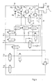
- FIG. 4 The embodiment of a further brake system according to Figure 4 differs from that of Figure 1 in particular by the design of the feed system E1.
- a dual-circuit pump 27a is provided for this feed system E 1.
- Corresponding pump check valves 29a and 29b connect the pump 27a to the return line 15.
- the pump check valves 30a and 30b are also connected downstream of the pump 27a.
- the pump check valves 29a, 29b and 30a, 30b are integral parts of the respective pump.
- the line 35a connects one pump circuit via the shut-off valve 36 to the pressure limiting valve 37.
- this pressure limiting valve is connected to the return line 15 as a pressure-controlled valve via line 55.
- the feed for the front axle brake circuit is regulated by the second circuit of the pump 27a via line 35b.
- This line is connected to the return line 15 by the pressure relief valve 38.
- this pressure relief valve 38 also has a connection 57 to the 1st brake circuit.
- a desired pressure difference between the I. and II. Brake circuit is in turn ensured by the pressure relief valve 37, which according to FIG. 2 has two surfaces which can be pressurized differently.
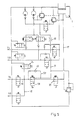
- FIG. 5 shows a further exemplary embodiment of a brake system according to the invention, in which case the feed valve 32 is replaced by a feed and shut-off valve 58.
- This combined valve 58 ensures the successive valve functions that would otherwise have to take place in succession as described in FIG. 1. In the position shown, the valve 58 blocks the line 31, while permitting the passage of brake fluid from the master cylinder 1 to the left and right rear wheels.
- valve 58 If the valve 58 is switched over, the main line 17 is blocked, but the feed line 31 is connected to the corresponding branch lines 18 and 19, respectively. Between line 31 and main line 17, valve 58 surrounds a further bypass 59, which is equipped with a check valve 60. It should possibly be ensured that the drain valve 24 can only be actuated when the combination valve 58 is switched. This can be done, for example, by a corresponding switch or a relay or the like.
- a throttle 61 is provided in line 31. This throttle limits the pressure build-up gradient in the wheel brake cylinders of the left and right rear wheels when switching to the feed mode to increase the rear axle brake pressure.
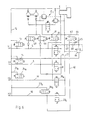
- FIG. 6 again shows an exemplary embodiment of an electrical or electronic brake force distribution according to the invention, specifically in a 4-channel anti-lock braking system.
- the brake circuit division is also black and white.
- a separate shut-off valve 20a or 20b is provided for both the left and the right rear wheel.
- each branch line 18 or 19 between the respective wheel brake cylinder and the shut-off valve 20a or 20b has a connection line 23a or 23b to the return line 15, the drain valves 24a or 24b switched on there being normal, conventional shut-off valves.
- the feed system E 1 corresponds to that of Figure 4.
- an additional line 62 is provided which connects the line 31 with the branch line 18.
- a further shut-off valve 63 is switched on, which is surrounded by a bypass 64 with a check valve 65.
- the pressure setting for traction control in this system serves a pressure relief valve 66 which is connected on the one hand to the bypass 64 and on the other hand to the return line 15. Through the pressure relief valve 66, there is a pressure comparison with the pressure in the main line 17 of the II. Brake circuit and with the pressure in the bypass line 64, a connection 67 via a check valve 68 to the feed line 31 being provided at the same time.
- a control unit 70 is provided, by means of which the entire brake system is controlled.
- This control unit includes a connection 71 to the wheel sensors (not shown in more detail), a further connection 72 to a servo pressure receptacle P Servo , a further connection 73 to a pressure receptacle P n for receiving the rear axle pressure, a connection 74 for receiving the front axle pressure P v and a connection 75 to accommodate the brake pedal travel S.
- the control unit controls the valves, only one output 76 being provided here for the sake of clarity.
- a motor 77 for the pump 27 is controlled via the control unit 70.
- Output 78 is provided for this purpose.
- a warning lamp 79 indicates faults in the brake system.
- the entire control unit has further connections 80 and 81 on the battery or ignition.
- the shut-off valves 7 and 8 are located in the 1st brake circuit for the wheels of the front axle.
- the check valves 11 and 12 already described above are also assigned to these shut-off valves.
- the feed valve 43 is provided in the present case between the pump 27 or a corresponding accumulator 82, but according to which the corresponding branch line 45 to the branch line 6 or the branch line 42 to the branch line 5 instead of the check valves 44 and 47 with additional solenoid valves 83 and 84 are occupied.
- These solenoid valves have a blocking position and a check position.
- shut-off valve 7 and 8 are switched to passage, while the drain valves 13 and 14 and the feed valve 43 and the solenoid valves 83 and 84 rest in the blocking position.
- pressure modulation in the wheel brake cylinders of the right and left front wheels is possible directly by actuating the master brake cylinder.
- shut-off valve 20 in the main line 17 of the II. Brake circuit to the wheels of the rear axle will be closed during partial braking. Also also the shut-off or selection valves 21 and 22.
- This feed system E2 differs from the one shown so far in that only one pressure relief valve 38 is present, since no differential pressure measurement is carried out in the feed system itself. The corresponding control takes over the control unit 70.
- the pressure modulation in the second brake circuit takes place in accordance with the ideal brake force distribution and controlled by the control unit 70. This compares the recorded pressure values P n and P v and modulates the brake pressure in the rear axle in accordance with a predetermined ideal curve.
- the feed valve 43, the shut-off valves 7 and 8 and the solenoid valves 83 and 84 are actuated by the control unit 70. This means that the shut-off valves 7 and 8 close while the Feed valve 43 opens.
- the two solenoid valves 83 and 84 go into the check position. Brake fluid can now be pumped from the pump 27 via the feed valve 43 and the solenoid valve 83 or 84 to the right or left front wheel brake cylinder. The pressure is adjusted via the feed valve 43.
- the pressure is then reduced via the drain valves 13 and 14, respectively, back into the return line 15.
- the corresponding wheel sensor detects this, so that, for example, the solenoid valve 84 then remains closed, while a pressure increase is carried out via the actuation time of the feed valve 43. If, for example, the wheel sensor of the left front wheel then additionally requests pressure build-up in the wheel brake cylinder of the left front wheel, the solenoid valve 84 is also opened.
- the line volume which is limited by the solenoid valves 83 and 84 and the feed valve 43, is approximately incompressible, so that no disturbance volume is stored.
- the solenoid valves 83 and 84 can nevertheless remain in the check position since the feed valve 43 is then closed.
- the pressure pick-up P Servo only shows the pressure which is present in the line between the feed valve 43 or the solenoid valve 83 and 84.
- the pressure pick-up P Servo shows the respective actual wheel pressure (with the solenoid valves 83 and 84 open).
- the control unit 70 does not permit a higher pressure P servo than that indicated by the pressure pickup P v , so that no higher pressure is fed into the front wheel brakes than specified by the driver.
- the characteristic curve does not become so large that the central valve in the master brake cylinder is damaged when the brake is released.
- additional pedal travel is permitted if necessary, be it by building up pressure in the main line 4 or the branch lines 5 and 6 via the shut-off valves 7 and 8 to the left and right front wheels or by volume displacement from the master brake cylinder into the reservoir 16 the shut-off valve 20 and the drain valve 24.
- a need arises especially when the relationship between the pedal travel and the front axle pressure P v required by the control unit 70 is not given.
- the curve of the required minimum pedal travel can also be made dependent on the increase in the coefficient of friction during the anti-lock control.
- the zero position of the pressure transducer P servo can be corrected by temporarily actuating the feed valve 43 and the solenoid valves 83 and 84 as long as there is no braking. This zero position also takes place automatically via the control unit.
- the state of bleeding of the 2nd brake circuit for the right and left rear wheel is monitored. This is done with a test cycle when the vehicle is stationary.
- the shut-off valve 20 is closed, the feed valve 32 is opened, the timing of the Pressure sensor P n is monitored.
- the time is determined which is required, for example, to increase the pressure to 20bar and then which time t2 is required to increase the pressure from 20bar to 50bar.
- the temperature of the liquid can be inferred from the time t2, so that a time tl can be calculated which is not exceeded if the venting state of the rear axle brake circuit is in order.
- This test cycle is based on the consideration that in the upper pressure range (above about 20 bar) the gradient is no longer dependent on the venting state.
- a circuit failure for example of the brake circuit I of the front axle, is recognized by the comparison between the brake pedal displacement sensor and the pressure sensor P v .
- a circuit failure is recognized via the activation time of the valves 7, 8, 43, 83 and 84.
- shut-off valve 20 is closed and entered through the feed system E2 brake fluid via line 31 and the feed valve 32 into the II. Brake circuit.
- shut-off or selection valves 21 and 22 are also open so that the brake fluid that is fed in can reach the wheel brake cylinders of the left and right rear wheels.
- the return takes place via the drain valve 24.
- the modulation takes place according to the known hydraulic multiplex method.
Abstract
Description
Die Erfindung betrifft eine Bremsanlage entsprechend dem Oberbegriff von Anspruch 1.The invention relates to a brake system according to the preamble of
Derartige Bremsanlagen mit einem Hauptbremszylinder, über welchen Bremskreise, insbesondere ein Bremskreis für die Vorderräder und ein Bremskreis für die Hinterräder, mit Bremsflüssigkeit versorgt werden, sind hinlänglich bekannt. Das gleiche gilt auch für eine entsprechende Absperrventilanordnung zur Antiblockierregelung.Brake systems of this type having a master brake cylinder, via which brake circuits, in particular a brake circuit for the front wheels and a brake circuit for the rear wheels, are supplied with brake fluid, are well known. The same also applies to a corresponding shut-off valve arrangement for anti-lock control.
Die Bremsauslegung für Fahrzeugachsen hat insbesondere die dynamischen Achslasten und deren Änderungen zu berücksichtigen. Im Idealfall ist die Bremskraft immer proportional der Abbremsung und der dynamischen Achslast. Diese "ideale" Bremskraftverteilung ändert sich mit der Abbremsung jedoch sehr stark.The brake design for vehicle axles has to take into account in particular the dynamic axle loads and their changes. Ideally, the braking force is always proportional to the braking and the dynamic axle load. However, this "ideal" braking force distribution changes very strongly with braking.
Nach den Richtlinien der EG und der ECE dürfen bei einer Abbremsung des Fahrzeuges bis 0,8g die Räder der Hinterachse nicht vor denjenigen der Vorderachse blockieren, weil bei zuerst blockierenden Rädern der Hinterachse ein Fahrzeug schleudert, während es bei zuerst blockierenden Rädern der Vorderachse zwar die Lenkfähigkeit verliert, aber relativ fahrstabil bleibt.According to the guidelines of the EC and ECE, when the vehicle is braked to 0.8g, the wheels of the rear axle must not lock in front of those on the front axle, because if the wheels of the rear axle lock first, a vehicle hurls, while if the front axle locks at first it loses steering ability, but remains relatively stable.
Die ideale Bremskraftverteilung wäre dann gegeben, wenn beide Achsen unabhängig vom Beladungszustand in gleichem Umfang zur Abbremsung beitragen würden. Dies ist jedoch kaum zu realisieren. Um die vorgegebenen Richtlinien einzuhalten, wird üblicherweise der Bremsdruck für die Hinterachse gemindert oder begrenzt oder eine Festabstimmung des Fahrzeuges mit sehr kleinen Radbremszylindern an der Hinterachse gewählt. Daraus resultiert jedoch eine Überbremsung der Vorderachse (nicht zu verwechseln mit Blockierung) gegenüber der Hinterachse. Zumindest bis zu einer Abbremsung von 0,8g wird dies so realisiert. Bei stärkeren Abbremsungen kann jedoch eine Umkehr der Blockierreihenfolge eintreten, da dann die Hinterachse überbremst wird. In jedem Fall trägt die jeweils überbremste Achse überproportional zur Abbremsung bei.The ideal distribution of braking force would be given if both axles contributed equally to braking, regardless of the load. However, this can hardly be realized. In order to comply with the specified guidelines, the brake pressure for the rear axle is usually reduced or limited, or a fixed set-up of the vehicle with very small wheel brake cylinders on the rear axle is selected. However, this results in overbraking of the front axle (not to be confused with locking) compared to the rear axle. This is achieved at least up to a deceleration of 0.8 g. In the event of more severe braking, however, the blocking order can be reversed, since the rear axle will then be braked. In any case, the braked axle contributes disproportionately to braking.
Die meisten Abbremsungen finden in einem Bereich von unter 0,3g statt. Durch die dauernde stärkere Belastung verschleißt die Bremsanlage an der Vorderachse erheblich schneller als an der Hinterachse. Zudem werden optimale Abbremsungen nicht realisiert, was besonders für schwere, leistungsfähige Fahrzeuge problematisch ist, bei denen die Belastbarkeitsgrenze der Vorderachse die möglichen Fahrleistungen einschränkt.Most decelerations take place in a range of less than 0.3g. Due to the constant heavy load, the brake system on the front axle wears considerably faster than on the rear axle. In addition, optimal braking is not achieved, which is particularly problematic for heavy, powerful vehicles in which the load capacity limit of the front axle limits the possible driving performance.
Bei einem funktionsfähigen Antiblockiersystem, welches die Stabilität eines Fahrzeuges gewährleistet, ist die zunehmende Unterbremsung der Hinterachse gegenüber der Vorderachse nicht nur unnötig, sondern verhindert sogar optimale Abbremsungen, da die Bremsdrücke deutlich unter der Blockiergrenze bleiben.With a functional anti-lock braking system, which ensures the stability of a vehicle, the increasing underbraking of the rear axle compared to the front axle is not only unnecessary, but also prevents optimal braking, since the braking pressures remain well below the blocking limit.
Ziel der vorliegenden Erfindung ist es, bei funktionsfähigem Antiblockiersystem eine hohe Druckaussteuerung in allen Radbremszylindern zu realisieren und trotzdem bei einem Ausfall des Antiblockiersystems das Kraftfahrzeug beherrschbar und stabil zu halten.The aim of the present invention is to realize a high pressure control in all wheel brake cylinders with a functional anti-lock braking system and nevertheless to keep the motor vehicle manageable and stable in the event of a failure of the anti-lock braking system.
Gemäß der vorliegenden Erfindung steht ein I. und II. Bremskreis nach den Absperrventilen mit einem Einspeisesystem in Verbindung, welches Einrichtungen zum Einspeisen von Bremsflüssigkeit unterschiedlichen Druckes in den I. und II. Bremskreis aufweist. Hierdurch wird eine Bremsdruckanhebung einzelner Kreise oder Räder im Normalbremsfall, d. h. ohne Antiblockierregelung, ermöglicht. Die Einspeisung der unterschiedlichen Drücke in den I. bzw. II. Bremskreis erfolgt fahrergesteuert und zwar so, daß nur eine relative Drucküberhöhung zwischen den Hinterachskreis gegenüber dem Vorderachskreis stattfindet. Hierdurch werden beispielsweise die bisher stark unterbremsten Bremseinrichtungen der Hinterachse vermehrt in einen Bremsvorgang einbezogen.According to the present invention, an I. and II. Brake circuit after the shut-off valves is connected to a feed system which has devices for feeding brake fluid of different pressures into the I and II. Brake circuit. This will increase the brake pressure of individual circles or wheels in the normal braking situation, i.e. H. without anti-lock control. The feeding of the different pressures into the 1st and 2nd brake circuits is controlled by the driver and in such a way that only a relative pressure increase takes place between the rear axle circuit compared to the front axle circuit. In this way, for example, the braking devices of the rear axle that have been severely braked so far are increasingly included in a braking operation.
Zur Regelung der Einspeisung sind zwischen dem I. bzw. II. Bremskreis und dem Einspeisesystem jeweils Einspeiseventile vorgesehen, über welche das Zuschalten des Einspeisesystems reguliert wird. Auf die Einspeiseventile für den I. Bremskreis folgen Rückschlagventile, welche verhindern, daß über zusätzliche Volumina und durch Leckagen im Einspeisesystem Fluid des I. Bremskreises verbraucht wird. Sie tragen so erheblich zur Sicherheit bei. Anstelle dieser Rückschlagventile können auch entsprechende Magnetventile mit einer Rückschlagposition vorgesehen sein. Als Fördereinrichtung für die zusätzliche Bremsflüssigkeit aus dem Einspeisesystem in den I. bzw. II. Bremskreis ist eine selbstansaugende Pumpe vorgesehen, wobei ihr, falls der Volumenstrom nicht ausreicht, zusätzlich ein Speicher zugeordnet ist. Es kann sich erfindungsgemäß sowohl um eine einkreisige wie auch um eine zweikreisige Pumpe handeln. In der Regel wird diese Pumpe separat elektromotorisch betrieben. Sie kann auch als Tandempumpe oder Flanschpumpe ausgebildet sein.To regulate the feed, feed valves are provided between the first and second brake circuits and the feed system, via which the connection of the feed system is regulated. Check valves follow the feed valves for the 1st brake circuit, which prevent fluid from the 1st brake circuit from being consumed by additional volumes and by leaks in the feed system. In this way, they contribute significantly to security. Instead of these check valves, corresponding solenoid valves with a check position can also be provided. As a delivery device for the additional brake fluid from the feed system into the 1st or 2nd brake circuit a self-priming pump is provided, and if the volume flow is not sufficient, an additional memory is assigned to it. According to the invention, it can be both a single-circuit and a double-circuit pump. As a rule, this pump is operated separately by an electric motor. It can also be designed as a tandem pump or flange pump.
In einem Ausführungsbeispiel der Erfindung ist die Pumpe über eine Leitung direkt mit dem Einspeiseventil des II. Bremskreises verbunden, während der Einspeisedruck für die Einspeiseventile des I. Bremskreises über Druckbegrenzungsventile angleichbar ist. Wenn im vorliegenden Fall vom I. bzw. II. Bremskreis gesprochen wird, so handelt es sich in der Regel um eine Schwarz-Weiß-Bremskreisaufteilung, wobei der II. Bremskreis die Radbremssysteme der Hinterachse und der I. Bremskreis die Radbremssysteme der Vorderachse mit Bremsflüssigkeit versorgt. Sollte es jedoch wünschenswert sein, so kann die Versorgung auch umgedreht geschehen.In one embodiment of the invention, the pump is connected via a line directly to the feed valve of the second brake circuit, while the feed pressure for the feed valves of the first brake circuit can be adjusted via pressure limiting valves. If in the present case one speaks of the 1st or 2nd brake circuit, it is usually a black-and-white brake circuit division, the 2nd brake circuit being the wheel brake systems of the rear axle and the 1st brake circuit being the wheel brake systems of the front axle with brake fluid provided. However, if it is desirable, the supply can also be reversed.
Wesentlich sind im vorliegenden Fall die Druckbegrenzungsventile. Über diese Druckbegrenzungsventile soll die Einspeisung in den I. Bremskreis so gesteuert werden, daß sie in Abhängigkeit eines Bremsdruckes im II. Bremskreis erfolgt. Aus diesem Grunde ist auch ein Druckbegrenzungsventil mit zwei gleich großen, hydraulisch beaufschlagten Flächen seines Ventilkörpers versehen, wobei die eine Fläche mit dem II. Bremskreis bevorzugt nahe dem Hauptbremszylinder verbunden ist. Bei dem anderen Druckbegrenzungsventil sind die beaufschlagten Flächen des Ventilkörpers verschieden groß, dabei steht die kleinere Fläche mit dem Lieferdruck der Pumpe in Verbindung. Als Gegenkräfte zu diesen Drücken findet der Vorderachs-Einspeisedruck, der zwischen den Druckbegrenzungsventilen herrscht, Verwendung und zwar sowohl für das erste wie auch für das zweite Ventil. Erhöht sich beispielsweise der Druck in der Speiseleitung nach dem ersten Druckbegrenzungsventil über den Druck, der in dem II. Bremskreis herrscht, so schaltet das Druckbegrenzungsventil durch und gibt den Weg für die Bremsflüssigkeit zurück zu einer Rückführleitung bzw. dem entsprechenden Vorratsbehälter frei. Dagegen wird durch das erste Druckbegrenzungsventil die Einspeiseleitung von der Pumpe zu dem I. Bremskreis dann geöffnet, wenn ein relativ höherer Druck vor der kleineren Fläche des Ventilkörpers aufgebaut ist. Wenn der überhöhte Druck auf die kleinere Fläche den Haltedruck auf die größere Fläche überwiegt, öffnet das Ventil und begrenzt den Einspeisedruck für den II. Bremskreis. Da der Gegenhaltedruck aber von dem Bremsdruck im II. Bremskreis abhängt, findet immer nur eine relative Überhöhung des Druckes in dem einen Bremskreis im Verhältnis zum Druck in dem anderen Bremskreis statt. Das Einspeisesystem kann niemals eine Bremsung gegen den Willen des Fahrers einleiten, wie dies bei vielen, vom Bremsdruck unabhängigen Systemen möglich ist.The pressure relief valves are essential in the present case. These pressure limiting valves are used to control the feed into the 1st brake circuit so that it takes place as a function of a brake pressure in the 2nd brake circuit. For this reason, a pressure relief valve is also provided with two hydraulically actuated surfaces of the same size on its valve body, one surface being preferably connected to the second brake circuit near the master brake cylinder. In the case of the other pressure relief valve, the pressurized areas of the valve body are of different sizes, the smaller area being connected to the delivery pressure of the pump. The front axle feed pressure that prevails between the pressure relief valves is used to counteract these pressures for both the first and the second valve. If, for example, the pressure in the feed line after the first pressure relief valve rises above the pressure prevailing in the second brake circuit, the pressure relief valve switches through and clears the way for the brake fluid back to a return line or the corresponding reservoir. In contrast, the first pressure limiting valve opens the feed line from the pump to the first brake circuit when a relatively higher pressure is built up in front of the smaller area of the valve body. If the excessive pressure on the smaller surface outweighs the holding pressure on the larger surface, the valve opens and limits the feed pressure for the 2nd brake circuit. However, since the counter pressure depends on the brake pressure in the second brake circuit, there is always only a relative increase in the pressure in one brake circuit in relation to the pressure in the other brake circuit. The infeed system can never initiate braking against the driver's will, as is possible with many systems that are independent of brake pressure.
Dabei soll es von untergeordneter Bedeutung sein, wie die einzelnen Druckbegrenzungsventile ausgestaltet sind. Wesentlich ist, daß zumindest in dem einen Druckbegrenzungsventil zwei verschieden große, hydraulisch beaufschlagte Flächen ausgebildet werden, wobei die eine, größere Fläche unter dem Druck des anderen Bremskreises steht.It should be of minor importance how the individual pressure relief valves are designed. It is essential that at least in the one pressure relief valve two differently sized, hydraulically acted surfaces are formed, one larger surface being under the pressure of the other brake circuit.
Im Rahmen der Erfindung liegt auch, daß eine möglicherweise vorgesehene Antriebsschlupfregelung ebenfalls über das Einspeisesystem erfolgt. Eine getrennte Regelung eines jeden Rades ist für den II. Bremskreis vorgesehen, bei dem die entsprechenden Regelventile für jedes Rad erst auf das entsprechende Einspeiseventil folgen. Die Bremsflüssigkeit zur Antriebsschlupfregelung liefert selbstverständlich die oben genannte Pumpe, wobei bei einer Antriebsschlupfregelung die Einspeiseventile offen sind.It is also within the scope of the invention that a possibly provided traction control system also takes place via the feed system. A separate control of each wheel is provided for the II. Brake circuit, in which the corresponding control valves for each wheel only follow the corresponding feed valve. The brake fluid the above-mentioned pump naturally provides for traction control, the feed valves being open in the case of traction control.
Im Falle der Verwendung einer zweikreisigen Pumpe bietet es sich an, auch die Druckbegrenzungsventile zu entkoppeln. Auch hier kommt es jedoch wieder auf das Verhältnis der hydraulisch beaufschlagten Fläche innerhalb des Druckbegrenzungsventiles an. In einem Ausführungsbeispiel ist dem I. Bremskreis das Druckbegrenzungsventil mit zwei gleichgroßen, hydraulisch beaufschlagten Flächen zugeordnet. Dieses Druckbegrenzungsventil ist mit dem I. Bremskreis nahe dem Hauptbremszylinder verbunden. Erhöht sich der Druck in diesem I. Bremskreis, so schaltet auch das Druckbegrenzungsventil erst bei einem erhöhten Einspeisedruck um.If a double-circuit pump is used, it is also advisable to decouple the pressure relief valves. Here too, however, the ratio of the hydraulically acted area inside the pressure relief valve is important. In one embodiment, the first brake circuit is assigned the pressure relief valve with two hydraulically actuated surfaces of the same size. This pressure relief valve is connected to the 1st brake circuit near the master brake cylinder. If the pressure in this first brake circuit increases, the pressure relief valve only switches over when the feed pressure is increased.
Ähnlich ist das zweite Druckbegrenzungsventil einerseits mit dem II. Bremskreis nahe dem Bremskraftverstärker und andererseits mit der Einspeiseleitung gekoppelt. Der Druck in der Einspeiseleitung beaufschlagt jedoch die kleinere Fläche, so daß hier der Einspeisedruck wesentlich erhöht werden kann, bevor das Druckbegrenzungsventil umschaltet.Similarly, the second pressure relief valve is coupled on the one hand to the II. Brake circuit near the brake booster and on the other hand to the feed line. However, the pressure in the feed line acts on the smaller area, so that here the feed pressure can be increased significantly before the pressure relief valve switches over.
Bei einem anderen Ausführungsbeispiel der Erfindung fehlt das eigentliche Einspeiseventil zwischen Pumpe und dem II. Bremskreis. Stattdessen ist ein Einspeise- und Absperrventil vorgesehen, wodurch die Regelung bzw. die Abstimmung zwischen Einspeisesystem und II. Bremskreis erleichtert wird. Eine Drossel, welche diesem Einspeise- und Absperrventil vorgeschaltet ist, begrenzt den Druckaufbaugradienten in den nachgeschalteten Radbremszylindern bei einem Umschalten auf eine elektrische bzw. elektronische Bremskraftverteilung.In another embodiment of the invention, the actual feed valve between the pump and the II. Brake circuit is missing. Instead, a feed and shut-off valve is provided, which makes it easier to regulate and coordinate the feed system and the second brake circuit. A throttle, which is upstream of this feed and shut-off valve, limits the pressure build-up gradient in the downstream wheel brake cylinders when switching over to an electrical or electronic brake force distribution.
Es versteht sich von selbst, daß die vorliegende Bremsanlage sowohl mit einem Drei- wie auch mit einem Vier-Kanal-Antiblockiersystem arbeiten kann. Auch dieses Vier-Kanal-Antiblockiersystem soll von dem vorliegenden Erfindungsgedanken umfaßt sein.It goes without saying that the present brake system can work with both a three and a four-channel anti-lock braking system. This four-channel anti-lock braking system is also intended to be encompassed by the present inventive concept.
Eine andere Möglichkeit der Bremskraftverteilung besteht darin die Druckaufnahme und Steuerung nicht den entsprechenden Druckbegrenzungsventilen zu überlassen, sondern hierzu eine Steuereinheit vorzusehen. Dabei erfolgt eine Druckaufnahme sowohl im I. wie auch im II. Bremskreis und im Einspeisesystem. Ferner wird zusätzlich auch der Pedalweg überwacht. Die Steuereinheit übernimmt dann die Regelung sämtlicher Ventile und auch des Motors des Einspeisesystems. In der Steuereinheit wird einmal der Druck in den beiden Bremskreisen miteinander verglichen und anhand einer Idealverteilung geregelt. Die Regelung geschieht dann durch Einspeisen von zusätzlicher Bremsflüssigkeit durch das Einspeisesystem in den entsprechenden Bremskreis. Aus diesem Grunde sind beide Bremskreise über ein entsprechendes Einspeiseventil mit dem Einspeisesystem verbunden. Weitere Ventile zur Regelung der Einspeisung sind selbstverständlich vorgesehen.Another possibility of braking force distribution is not to leave the pressure absorption and control to the corresponding pressure limiting valves, but to provide a control unit for this purpose. Pressure is recorded in both the 1st and 2nd brake circuits and in the feed system. The pedal travel is also monitored. The control unit then takes over the regulation of all valves and also the motor of the feed system. The pressure in the two brake circuits is compared with one another in the control unit and regulated using an ideal distribution. The regulation then takes place by feeding additional brake fluid through the feed system into the corresponding brake circuit. For this reason, both brake circuits are connected to the feed system via a corresponding feed valve. Further valves for regulating the feed are of course provided.
Die Steuereinheit übernimmt auch die Regelung eines Antiblockierfalles, wobei die entsprechenden Ventile gesperrt und andere Ventile zur Druckentlassung geöffnet werden.The control unit also takes over the control of an anti-lock case, the corresponding valves being blocked and other valves being opened for pressure release.
Mit Hilfe des Pedalweggebers wird dafür gesorgt, daß bei Reibwerterhöhung während eines Antiblockierfalles die Kennlinienverschiebung so groß wird, daß beim Lösen der Bremse das Zentralventil im Hauptbremszylinder nicht beschädigt wird. Dies wird damit erreicht, daß im Bedarfsfall zusätzlicher Pedalweg freigegeben wird, was entweder durch einen Druckaufbau im I. Bremskreis oder durch Volumenverschiebung aus dem Hauptbremszylinder in den Vorratsbehälter erfolgt. Auch hier kommt es auf den Vergleich eines vorgegebenen Pedalweges mit dem ermittelten Druck im I. Bremskreis an.With the help of the pedal travel sensor, it is ensured that when the coefficient of friction increases during an anti-lock case, the characteristic curve becomes so large that the central valve in the master cylinder is not damaged when the brake is released. This is achieved in that additional pedal travel is released if necessary, either by a pressure build-up in the 1st brake circuit or by volume shift from the master brake cylinder into the reservoir. Here, too, it is important to compare a specified pedal travel with the pressure determined in the first brake circuit.
Ein wesentlicher Vorteil der Anordnung mit der Steuereinheit liegt darin, daß die Nullstellung der Drucksensoren korrigiert werden kann, wenn keine Bremsung stattfindet. Dies geschieht automatisch über die Steuereinheit durch Betätigung der einzelnen Ventile.An important advantage of the arrangement with the control unit is that the zero position of the pressure sensors can be corrected when there is no braking. This is done automatically via the control unit by operating the individual valves.
Ebenso ist ein Testzyklus für den Entlüftungszustand der Hinterachse bei stillstehendem Fahrzeug vorgesehen. Bei diesem Testzyklus wird der II. Bremskreis für die Hinterachse unter Druck gesetzt und die Zeit ermittelt, welche benötigt wird, um einen bestimmten Druckaufbau bzw. die Differenz zwischen zwei Druckwerten zu überwinden. Daraus läßt sich eine Zeit errechnen, die bei einem Druckaufbau nicht überschritten werden darf, wenn der Entlüftungszustand in Ordnung ist.A test cycle is also provided for the state of ventilation of the rear axle when the vehicle is stationary. In this test cycle, the second brake circuit for the rear axle is pressurized and the time which is required to overcome a specific pressure build-up or the difference between two pressure values is determined. This can be used to calculate a time that should not be exceeded when the pressure builds up if the ventilation status is correct.
Auch die Antriebsschlupfregelung erfolgt über das Einspeisesystem entsprechend dem bekannten hydraulischen Multiplexverfahren.The traction control is also carried out via the feed system in accordance with the known hydraulic multiplex method.
Weitere Vorteile, Merkmale und Einzelheiten der Erfindung ergeben sich aus der nachfolgenden Beschreibung bevorzugter Ausführungsbeispiele sowie anhand der Zeichnung; diese zeigt in
Figur 1 ein Blockschaltbild einer erfindungsgemäßen Bremsanlage mit elektrischer bzw. elektronischer Bremskraftverteilung;Figur 2 einen schematischen Längsschnitt durch ein Druckbegrenzungsventil;Figur 3 einen schematischen Längsschnitt durch ein weiteres Druckbegrenzungsventil;Figur 4 ein Blockschaltbild einer weiteren Ausführungsform einer elektrischen bzw. elektronischen Bremskraftverteilung;Figur 5 ein Blockschaltbild eines weiteren Ausführungsbeispiels einer elektrischen bzw. elektronischen Bremskraftverteilung;Figur 6 ein Blockschaltbild eines weiteren Ausführungsbeispiels einer elektrischen bzw. elektronischen Bremskraftverteilung;Figur 7 ein Blockschaltbild eines weiteren Ausführungsbeispiels einer elektrischen bzw. elektronischen Bremskraftverteilung.
- Figure 1 is a block diagram of a brake system according to the invention with electrical or electronic brake force distribution;
- Figure 2 shows a schematic longitudinal section through a pressure relief valve;
- Figure 3 shows a schematic longitudinal section through a further pressure relief valve;
- FIG. 4 shows a block diagram of a further embodiment of an electrical or electronic braking force distribution;
- Figure 5 is a block diagram of another embodiment of an electrical or electronic brake force distribution;
- FIG. 6 shows a block diagram of a further exemplary embodiment of an electrical or electronic brake force distribution;
- Figure 7 is a block diagram of another embodiment of an electrical or electronic brake force distribution.
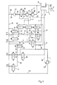
Gemäß Figur 1 weist eine Bremsanlage einen I. und einen II. Bremskreis auf. Beide Bremskreise münden aus einem entsprechenden Hauptbremszylinder 1, dessen nähere Ausgestaltung für zwei Bremskreise allgemein bekannt ist. Der Hauptbremszylinder 1 wird über eine Kolbenstange 2 mit Bremsdruck beaufschlagt, welcher von einem Bremspedal 3 vom Fuße eines Fahrers übertragen wird.According to FIG. 1, a brake system has an I. and a II. Brake circuit. Both brake circuits open from a corresponding
Über den I. Bremskreis werden das linke und rechte Vorderrad bzw. deren nicht näher gezeigte Radbremszylinder mit Bremsflüssigkeit versorgt. Dies geschieht über eine gemeinsame Hauptleitung 4, welche sich in zwei Zweigleitungen 5 und 6 aufteilt. In jede Zweigleitung 5 bzw. 6 ist ein Absperrventil 7 bzw. 8 eingeschaltet, mittels denen die jeweilige Zweigleitung 5 bzw. 6 von der Hauptleitung 4 abgesperrt werden kann. Beide Absperrventile 7 bzw. 8 können durch eine Bypaßleitung 9 bzw. 10, in welche jeweils ein Rückschlagventil 11 bzw. 12 eingeschaltet ist, umgangen werden.The left and right front wheels or their wheel brake cylinders (not shown in detail) are supplied with brake fluid via the first brake circuit. This is done via a common
Zum Abbau eines Bremsdruckes beispielsweise bei einer auftretenden Antiblockierregelung ist jede Zweigleitung 5 bzw. 6 durch ein weiteres Ablaßventil 13 bzw. 14 mit einer Rücklaufleitung 15 zu einem Vorratsbehälter 16 verbunden.To reduce a brake pressure, for example when an anti-lock control occurs, each
Der II. Bremskreis besitzt ebenfalls eine Hauptleitung 17, welche sich in zwei Zweigleitungen 18 und 19 aufteilt. Vor der Aufteilung ist ein Absperrventil 20 vorgesehen, durch welches die Hauptleitung 17 gesperrt werden kann. In jede Zweigleitung 18 bzw. 19 ist ferner noch ein Absperr- und Auswahlventil 21 bzw. 22 eingeschaltet, welches, wie später beschrieben, der Antriebsschlupfregelung dient. Hierzu besitzen beide Zweigleitung 18 bzw. 19 einen Anschluß über eine Anschlußleitung 23 und ein Ventil 24 zu der Rücklaufleitung 15. Dieses Ventil 24 besitzt zum einen eine Rücklaufposition für den Abbau von Bremsdruck und zum anderen eine Rückschlagposition 26.The II. Brake circuit also has a
Beiden Bremskreisen I und II ist ein Einspeisesystem E zugeordnet. Im vorliegenden Ausführungsbeispiel weist dieses Einspeisesystem E eine einkreisige Pumpe auf, welche bevorzugt selbstansaugend ausgebildet ist. Falls jedoch der Volumenstrom nicht ausreicht, sollte noch eine zusätzliche Speichereinleitung vorgesehen sein. Ferner handelt es sich bei der Pumpe um eine separate, elektromotorisch betriebene Pumpe, welche auch eine Tandem- bzw. Flanschpumpe sein kann. Diese Pumpe 27 fördert Bremsflüssigkeit in dem Einspeisesystem E. Diese Bremsflüssigkeit entnimmt sie dem Vorratsbehälter 16, wobei in die entsprechende Anschlußleitung 28 ein Pumpenrückschlagventil 29 eingeschaltet ist.An infeed system E is assigned to both brake circuits I and II. In the present exemplary embodiment, this feed system E has a single-circuit pump, which is preferably designed to be self-priming. However, if the volume flow is not sufficient, an additional one should be added Memory initiation may be provided. Furthermore, the pump is a separate pump operated by an electric motor, which can also be a tandem or flange pump. This
Die Förderung der Bremsflüssigkeit erfolgt durch ein weiteres Pumpenrückschlagventil 30, nach welchem eine Leitung 31 abzweigt, die mit der Hauptleitung 17 des II. Bremskreises nach dem Absperrventil 20 verbunden ist. Beide Pumpenrückschlagventile 29,30 sind integrierte Elemente der Pumpe 27. Ferner ist in die Leitung 31 auch ein Einspeiseventil 32 eingeschaltet, über welches die Leitung 31 geschlossen werden kann. Für dieses Einspeiseventil 32 ist wiederum ein Bypaß 33 mit einem entsprechenden Rückschlagventil 34 vorgesehen.The brake fluid is conveyed through a further
Eine weitere Leitung 35 führt nach dem Rückschlagventil 30 durch ein Absperrventil 36 zu einem Druckbegrenzungsventil 37. Diesem Druckbegrenzungsventil 37 folgt ein zweites Druckbegrenzungsventil 38 nach, welches über eine Verbindungsleitung 39 zur Rücklaufleitung 15 führt. Dabei handelt es sich hier um ein druckgesteuertes Ventil.A further line 35 leads after the
Zwischen Druckbegrenzungsventil 37 und Druckbegrenzungsventil 38 zweigt eine Einspeiseleitung 41 ab, welche sich aufzweigt und mit einer Zweigleitung 42 über ein Einspeiseventil 43 sowie ein darauf folgendes Rückschlagventil 44 mit der Zweigleitung 5 zum linken Vorderrad verbunden ist. Eine zweite Zweigleitung 45 mit eingeschaltetem Einspeiseventil 46 und darauf folgendem Rückschlagventil 47 führt zur Zweigleitung 6 zum rechten Vorderrad.Between the
Ferner besitzt die Rücklaufleitung 15 noch einen Anschluß 48 an die Leitung 31 und zwar nach dem Einspeiseventil 32. In diesen Anschluß ist ein Differenzdruckbegrenzungsventil 49 als druckbeaufschlagtes Ventil eingesetzt, welches eine nur gestrichelt dargestellte Verbindung 50 zur Hauptleitung 17 des II. Bremskreises besitzt.Furthermore, the
Die Funktionsweise der erfindungsgemäßen Bremsanlage ist folgende:
- 1. Eine Normalbremsung ist auf konventionellem Wege im Bremskreis I möglich, wobei durch den
Druckaufbau im Hauptbremszylinder 1 der Bremskreis I mit Bremsdruck versorgt wird, wobei dieser Bremsdruck dann auf die entsprechenden Radbremszylinder im linken und rechten Vorderrad wirkt. Für die Hinterachse wird überdas Einspeiseventil 32 Fluid mit erhöhtem Druck gegenüber dem Bremskreis I hinterdem Absperrventil 20 eingespeist, womit die Radbremszylinder der Hinterradbremsen versorgt werden. - 2. Beim Auftreten einer Antiblockierregelung schließen die
Absperrventile Einspeiseventile und 46 sowie die entsprechenden Ablaßventile 13, 14und 24 moduliert.Die Pumpe 27 läuft dabei entweder dauernd oder fördert Bremsflüssigkeit ab Bremsbeginn. - 3. Eine Antriebsschlupfregelung erfolgt über die Absperr-
und Auswahlventile und 36, wobei die Einspeisung bei Hinterradantrieb überdas Einspeiseventil 32 erfolgt. Die Druckbegrenzung für ASR übernimmt bei geschlossenem Absperrventil 36 das differenzdruckgesteuerte Druckbegrenzungsventil 49 (Systemschutzfunktion).
- 1. Normal braking is possible in a conventional manner in brake circuit I, the brake circuit I being supplied with brake pressure by the pressure build-up in
master brake cylinder 1, this brake pressure then acting on the corresponding wheel brake cylinders in the left and right front wheels. For the rear axle, fluid is fed in via thefeed valve 32 at a higher pressure than the brake circuit I behind the shut-offvalve 20, which supplies the wheel brake cylinders of the rear wheel brakes. - 2. When an anti-lock control occurs, the shut-off
valves valve 20 remain closed. As a result, the correspondingmain lines feed valves corresponding drain valves pump 27 either runs continuously or delivers brake fluid from the start of braking. - 3. A traction control takes place via the shut-off and
selection valves feed valve 32. When the shut-offvalve 36 is closed, the differential pressure-controlled pressure relief valve 49 (system protection function) takes over the pressure limitation for ASR.
Das Absperrventil 20 ist im übrigen normalerweise auf Sperrstellung geschaltet und zwar sowohl bei Normalbremsung wie auch bei einer Antiblockier- bzw. Antriebsschlupfregelung. Es nimmt nur bei Servodruckausfall, was beispielsweise beim Ausfall der Pumpe 27 geschehen kann, seine Offenstellung ein. Eine Bremsung der Räder der Hinterachse über den Hauptbremszylinder ist immer möglich, d. h. in Notsituationen bleibt eine volle Bremsflüssigkeitsreserve für den II. Bremskreis bestehen. Die Nachsaugmöglichkeit für die Radbremszylinder des linken und rechten Hinterrades gewährleitstet die Rückschlagposition des Ablaßventil 24.The shut-off
Bei Ausfall des Bremskreises I bzw. II bleibt der jeweils andere Bremskreis intakt, während das Einspeisesystem abgeschaltet wird.If brake circuit I or II fails, the other brake circuit remains intact while the supply system is switched off.
Die Bremskraftverteilung wird im wesentlichen über die Druckbegrenzungsventile 37 bzw. 38 gesteuert. Hierzu ist das Druckbegrenzungsventil 37 mit zwei verschieden großen, hydraulisch beaufschlagten Flächen versehen, wie dies in Figur 2 angedeutet ist. Dort wird ein entsprechender Ventilkörper 51 unter dem Druck einer Schraubenfeder 52 in der gezeigten Lage gehalten. Den Druck der Schraubenfeder unterstützt ein Einspeisedruck PE, welcher in der Einspeiseleitung 41 vorherrscht.The braking force distribution is essentially controlled via the
Der Ventilkörper 51 besitzt einen Durchmesser d₂, welcher größer ist als der Durchmesser d₁ der Leitung 35. In dieser Leitung steht der Servodruck PServo an. Allerdings wird die Leitung 35 durch den Ventilkörper 51 verschlossen und so von der Einspeiseleitung getrennt. Zum Öffnen dieses Druckbegrenzungsventiles muß der Druck PServo größer sein als der Haltedruck PE`The
Das auf das Druckbegrenzungsventil 37 folgende Druckbegrenzungsventil 38 besitzt zum einen den Anschluß an die Einspeiseleitung 41, in welche der Einspeisedruck PE wirksam ist. Über einen weiteren Ventilkörper 51a mit dem Durchmesser d₂ wird eine Ventilkugel 53 gegen die Öffnung der Einspeiseleitung 41 gedrückt, wobei der entsprechende wirksame Ventilsitz einen Durchmesser von d₃ aufweist. In diesem Fall ist d₃ gleich d₂. Solange die Kugel 53 die Leitung 41 verschlossen hält, wird eine Verbindung zwischen Einspeiseleitung 41 und Verbindungsleitung 39 zum Rücklauf bzw. Vorratsbehälter 16 unterbrochen. Die Schließkraft des Ventilkörpers 51a wird zum einen durch eine Schraubenfeder 54 und zum anderen durch die Druckererfassung über die Verbindung 40 zum Hauptbremszylinder 1 hin aufrecht erhalten.The pressure relief valve following the
Durch eine derartige erfindungsgemäße Bremskraftverteilung tritt keine Pedalrückwirkung auf. Es findet auch kein kurzes, sprunghaftes Ansteigen des Druckes in den Radbremszylindern statt. Es erfolgt nur eine relative Überhöhung des Druckes in den Radbremszylindern der Räder der Hinterachse gegenüber demjenigen in den Radbremszylindern der Räder der Vorderachse. Eine absolute Drucküberhöhung findet nicht statt. Diese wichtige Sicherheitsfunktion gewährleistet, daß das Einspeisesystem niemals eine Bremsung gegen den Willen des Fahrers einleiten kann, wie dies beispielsweise bei den vollkommen von einer Fahrertätigkeit abgekoppelten Systemen möglich ist.With such a brake force distribution according to the invention, there is no pedal reaction. There is also no short, sudden increase in pressure in the wheel brake cylinders. There is only a relative increase in the pressure in the wheel brake cylinders of the wheels of the rear axle compared to that in the wheel brake cylinders of the wheels of the front axle. There is no absolute pressure increase. This important safety function ensures that the feed system can never initiate braking against the will of the driver, as is possible, for example, in the case of systems which are completely decoupled from driver activity.
Bei der vorliegenden Bremsanlage findet eine Sensierung folgender Funktionen statt:
- Radverhalten durch entsprechnde Radsensoren
- ein Druckdifferenzsensor erkennt einen Kreisausfall im Hauptbremszylinder
- Funktion der Servopumpe.
- Wheel behavior through appropriate wheel sensors
- a pressure difference sensor detects a circuit failure in the master brake cylinder
- Function of the servo pump.
Sollten die Sensoren entsprechendes Fehlverhalten melden, so müssen über ein nicht näher dargestelltes Steuergerät die gewünschten Schaltungen im Einspeisesystem und dem System der restlichen Bremsanlage vorgenommen werden.If the sensors report corresponding malfunctions, the desired circuits in the infeed system and the system of the rest of the brake system must be carried out via a control unit (not shown).
Die Bremsanlage gemäß Figur 1 bezieht sich im übrigen auf ein 3-Kanal-Antiblockiersystem bei Schwarz-Weiß-Bremskreisaufteilung. Für ein 4-Kanal-Antiblockiersystem kann dieselbe Konfiguration Anwendung finden und ist ohne prinzipielle Unterschiede und größere Änderungen realisierbar.The brake system according to FIG. 1 also refers to a 3-channel anti-lock braking system with black and white brake circuit division. The same configuration can be used for a 4-channel anti-lock braking system and can be implemented without fundamental differences and major changes.
Wird aus bestimmten Gründen für das Absperrventil 20 ein stromlos offenes 2/2-Magnetventil vorgesehen, so ist das Einspeiseventil 32 in Ausgangsstellung (stromlos) geschlossen. Das Absperrventil 20 muß nun bei jeder Bremsung vor dem Einspeiseventil 32 geschaltet werden, da sonst eine deutliche Pedalrückwirkung auftreten und der Hauptbremszylinderkolben zurückgeschoben würde. Hierdurch könnten Schäden am Zentralventil des Hauptbremszylinders auftreten. Der Druck in den Radbremszylindern würde zudem sprungartig ansteigen, wodurch der Fahrkomfort leidet und zudem eine häufige Antiblockierregelung provoziert würde. Das Absperrventil 20 muß bei einer Bremsbetätigung schnell schalten, um eine ausreichende Fluidmenge im Hauptbremszylinder vorzuhalten.If, for certain reasons, a normally open 2/2 solenoid valve is provided for the shut-off
Das Ausführungsbeispiel einer weiteren Bremsanlage gemäß Figur 4 unterscheidet sich von derjenigen nach Figur 1 insbesondere durch die Ausgestaltung des Einspeisesystems E₁. Für dieses Einspeisesystem E₁ ist eine zweikreisige Pumpe 27a vorgesehen. Entsprechende Pumpenrückschlagventile 29a und 29b verbinden die Pumpe 27a mit der Rücklaufleitung 15. Ebenfalls sind der Pumpe 27a die Pumpenrückschlagventile 30a und 30b nachgeschaltet. Die Pumpenrückschlagventile 29a,29b bzw. 30a,30b sind integrale Bestandteile der jeweiligen Pumpe.The embodiment of a further brake system according to Figure 4 differs from that of Figure 1 in particular by the design of the feed system E₁. A dual-circuit pump 27a is provided for this
Den einen Pumpenkreis verbindet die Leitung 35a über das Absperrventil 36 mit dem Druckbegrenzungsventil 37. Dieses Druckbegrenzungsventil ist im vorliegenden Ausführungsbeispiel als druckgesteuertes Ventil mit dem Rücklauf 15 über die Leitung 55 verbunden.The
Die Regelung der Einspeisung für den Vorderachsenbremskreis erfolgt dagegen durch den zweiten Kreis der Pumpe 27a über die Leitung 35b. Diese Leitung wird durch das Druckbegrenzungsventil 38 mit der Rücklaufleitung 15 verbunden. Ferner besitzt dieses Druckbegrenzungsventil 38 auch einen Anschluß 57 an den I. Bremskreis. Ein erwünschter Druckunterschied zwischen dem I. und II. Bremskreis wird wiederum durch das Druckbegrenzungsventil 37 gewährleistet, welches entsprechend Figur 2 zwei unterschiedlich mit Druck beaufschlagbare Flächen besitzt.In contrast, the feed for the front axle brake circuit is regulated by the second circuit of the pump 27a via
In Figur 5 ist ein weiteres Ausführungsbeispiel einer erfindungsgemäßen Bremsanlage gezeigt, wobei dort das Einspeiseventil 32 durch ein Einspeise- und Absperrventil 58 ersetzt ist. Durch dieses kombinierte Ventil 58 sind die aufeinanderfolgenden Ventilfunktionen gewährleistet, die sonst nacheinander gemäß der Beschreibung zu Figur 1 ablaufen müssen. In der gezeigten Stellung sperrt das Ventil 58 die Leitung 31, während es den Durchlaß von Bremsflüssigkeit aus dem Hauptbremszylinder 1 zum linken und rechten Hinterrad zuläßt.FIG. 5 shows a further exemplary embodiment of a brake system according to the invention, in which case the
Wird das Ventil 58 umgeschaltet, so ist die Hauptleitung 17 gesperrt, jedoch die Speiseleitung 31 mit den entsprechenden Zweigleitungen 18 bzw. 19 verbunden. Zwischen Leitung 31 und Hauptleitung 17 umgibt das Ventil 58 ein weiterer Bypaß 59, der mit einem Rückschlagventil 60 besetzt ist. Es sollte eventuell sichergestellt werden, daß das Ablaßventil 24 erst betätigt werden kann, wenn das Kombinationsventil 58 umgeschaltet ist. Dies kann beispielsweise durch einen entsprechenden Schalter bzw. ein Relais od. dgl. erfolgen.If the
Des weiteren ist eine Drossel 61 in der Leitung 31 vorgesehen. Durch diese Drossel findet eine Begrenzung des Druckaufbaugradienten in den Radbremszylindern des linken und rechten Hinterrades bei Umschaltung auf den Einspeisebetrieb zur Anhebung des Hinterachsbremsdruckes statt.Furthermore, a
In Figur 6 ist wiederum ein Ausführungsbeispiel einer erfindungsgemäßen elektrischen bzw. elektronischen Bremskraftverteilung gezeigt und zwar in einem 4-Kanal-Antiblockiersystem. Die Bremskreisaufteilung ist ebenfalls Schwarz-Weiß. Sowohl für das linke wie auch für das rechte Hinterrad ist ein getrenntes Absperrventil 20a bzw. 20b vorgesehen. Ebenfalls ist jede Zweigleitung 18 bzw. 19 zwischen dem jeweiligen Radbremszylinder und dem Absperrventil 20a bzw. 20b eine Anschlußleitung 23a bzw. 23b zur Rücklaufleitung 15 vorhanden, wobei die dort eingeschalteten Ablaßventile 24a bzw. 24b normale übliche Absperrventile sind.FIG. 6 again shows an exemplary embodiment of an electrical or electronic brake force distribution according to the invention, specifically in a 4-channel anti-lock braking system. The brake circuit division is also black and white. A separate shut-off
Das Einspeisesystem E₁ entspricht demjenigen nach Figur 4. Zum getrennten Einspeisen für das linke und das rechte Hinterrad ist jedoch eine Zusatzleitung 62 vorgesehen, welche die Leitung 31 mit der Zweigleitung 18 verbindet. In diese Leitung 62 ist ein weiteres Absperrventil 63 eingeschaltet, welches von einem Bypaß 64 mit Rückschlagventil 65 umgeben ist.The
Der Druckeinstellung für Antriebsschlupfregelung in diesem System dient ein Druckbegrenzungsventil 66, welches einerseits an den Bypaß 64 und andererseits an die Rückführleitung 15 angeschlossen ist. Durch das Druckbegrenzungsventil 66 findet ein Druckvergleich mit dem Druck in der Hauptleitung 17 des II. Bremskreises sowie mit dem Druck in der Bypaßleitung 64 statt, wobei hier gleichzeitig eine Verbindung 67 über ein Rückschlagventil 68 zu der Einspeiseleitung 31 gegeben ist.The pressure setting for traction control in this system serves a
In dem Ausführungsbeispiel einer erfindungsgemäßen Bremsanlage gemäß Figur 7 ist eine Steuereinheit 70 vorgesehen, über welche die gesamte Bremsanlage gesteuert wird. Dieses Steuergerät beinhaltet einen Anschluß 71 an die nicht näher gezeigten Radsensoren, einen weiteren Anschluß 72 an eine Servodruckaufnahme PServo, einen weiteren Anschluß 73 an eine Druckaufnahme Pn zur Aufnahme des Hinterachsendruckes, einen Anschluß 74 zur Aufnahme des Vorderachsendruckes Pv sowie einen Anschluß 75 zur Aufnahme des Bremspedalweges S. Ferner übernimmt die Steuereinheit die Steuerung der Ventile, wobei hier der Übersichtlichkeit halber nur ein Ausgang 76 vorgesehen ist. Des weiteren wird über die Steuereinheit 70 ein Motor 77 für die Pumpe 27 angesteuert. Hierzu ist der Ausgang 78 vorgesehen. Eine Warnlampe 79 zeigt Störungen in der Bremsanlage an. Die gesamte Steuereinheit besitzt weitere Anschlüsse 80 und 81 an Batterie bzw. Zündung.In the exemplary embodiment of a brake system according to the invention according to FIG. 7, a
Im I. Bremskreis für die Räder der Vorderachse befinden sich die Absperrventile 7 und 8. Diesen Absperrventilen sind gleichfalls die bereits oben beschriebenen Rückschlagventile 11 und 12 zugeordnet. Anstelle der beiden Einspeiseventile 43 und 46 mit den Rückschlagventilen 44 und 47 ist jedoch im vorliegenden Fall zwischen der Pumpe 27 bzw. einem entsprechenden Speicher 82 nur das Einspeiseventil 43 vorgesehen, nach welchem jedoch die entsprechende Zweigleitung 45 zu der Zweigleitung 6 bzw. die Zweigleitung 42 zu der Zweigleitung 5 anstelle der Rückschlagventile 44 bzw. 47 mit zusätzlichen Magnetventilen 83 bzw. 84 besetzt sind. Diese Magnetventile besitzen eine Sperrstellung und eine Rückschlagposition.The shut-off
Bei einer Teilbremsung sind das Absperrventil 7 und 8 auf Durchlaß geschaltet, während die Ablaßventile 13 und 14 sowie das Einspeiseventil 43 und die Magnetventile 83 und 84 in Sperrstellung ruhen. Hierdurch ist eine Druckmodulation in den Radbremszylindern des rechten und linken Vorderrades direkt durch Betätigung des Hauptbremszylinders möglich.In the event of partial braking, the shut-off
Bei intakter Steuereinheit 70 wird bei Teilbremsung das Absperrventil 20 in der Hauptleitung 17 des II. Bremskreises zu den Rädern der Hinterachse geschlossen sein. Ebenfalls auch die Absperr- bzw. Auswahlventile 21 und 22. Hier findet eine Druckmodulation über Einspeisung von Bremsflüssigkeit durch die Leitung 31 und das Einspeiseventil 32 über ein Einspeisesystem E₂ statt. Dieses Einspeisesystem E₂ unterscheidet sich von dem bisher gezeigten dadurch, daß nur ein Druckbegrenzungsventil 38 vorhanden ist, da hier keine Differenzdruckmessung im Einspeisesystem selbst vorgenommen wird. Die entsprechende Steuerung übernimmt die Steuereinheit 70.If the
Die Druckmodulation in dem II. Bremskreis erfolgt entsprechend der idealen Bremskraftverteilung und gesteuert durch die Steuereinheit 70. Diese vergleicht die aufgenommenen Druckwerte Pn und Pv und moduliert den Bremsdruck in der Hinterachse entsprechend einer vorgegebenen Idealkurve.The pressure modulation in the second brake circuit takes place in accordance with the ideal brake force distribution and controlled by the
Tritt der Fall einer Antiblockierregelung an einem Rad der Vorderachse auf, so werden von der Steuereinheit 70 das Einspeiseventil 43, die Absperrventile 7 und 8 sowie die Magnetventile 83 und 84 angesteuert. Dies bedeutet, daß die Absperrventile 7 und 8 schließen, während das Einspeiseventil 43 öffnet. Die beiden Magnetventile 83 und 84 gehen in Rückschlagposition. Nunmehr kann von der Pumpe 27 Bremsflüssigkeit über das Einspeiseventil 43 sowie das Magnetventil 83 bzw. 84 zum rechten bzw. linken Vorderradbremszylinder gefördert werden. Die Druckeinstellung erfolgt über das Einspeiseventil 43.If the case of an anti-lock control occurs on a wheel of the front axle, the
Eine Druckreduzierung erfolgt dananch über die Ablaßventile 13 bzw. 14 zurück in den Rücklauf 15.The pressure is then reduced via the
Sollte beispielsweise im Falle einer Antiblockierregelung nur das rechte Vorderrad geregelt werden, so stellt dies der entsprechende Radsensor fest, so daß beispielsweise dann das Magnetventil 84 geschlossen bleibt, während über die Ansteuerzeit des Einspeiseventils 43 eine Druckerhöhung durchgeführt wird. Fordert dann beispielsweise der Radsensor des linken Vorderrades zusätzlich einen Druckaufbau im Radbremszylinder des linken Vorderrades, so wird auch das Magnetventil 84 geöffnet. Das Leitungsvolumen, welches durch die Magnetventile 83 und 84 sowie das Einspeiseventil 43 begrenzt ist, ist annähernd inkompressibel, so daß kein Störvolumen gespeichert wird.If, for example, in the case of an anti-lock control, only the right front wheel is controlled, the corresponding wheel sensor detects this, so that, for example, the
Verlangt kein Vorderrad einen Druckaufbau, so können die Magnetventile 83 und 84 dennoch in Rückschlagposition verbleiben, da dann das Einspeiseventil 43 geschlossen ist. In diesem Fall zeigt die Druckaufnahme PServo nur den Druck an, welcher in der Leitung zwischen Einspeiseventil 43 bzw. dem Magnetventil 83 und 84 vorhanden ist. Während der Druckaufbauzeit bzw. nach Öffnen des Einspeiseventils 43 zeigt die Druckaufnahme PServo den jeweiligen tatsächlichen Raddruck an (bei geöffneten Magnetventilen 83 und 84). Dabei läßt die Steuereinheit 70 im Falle des funktionsfähigen Systems keinen höheren Druck PServozu, als denjenigen von der Druckaufnahme Pv angezeigten Druck, so daß in die Vorderradbremsen kein höherer Druck eingespeist wird als vom Fahrer vorgegeben.If no front wheel demands pressure build-up, the
Mit Hilfe des Pedalweggebers S wird dafür gesorgt, daß bei einer Reibwerterhöhung während der Antiblockierregelung die Kennlinienverschiebung nicht so groß wird, daß beim Lösen der Bremse das Zentralventil im Hauptbremszylinder beschädigt wird. Dies wird dadurch erreicht, daß im Bedarfsfall zusätzlicher Pedalweg zugelassen wird, sei es durch Druckaufbau in der Hauptleitung 4 bzw. den Zweigleitungen 5 und 6 über die Absperrventile 7 und 8 zum linken und rechten Vorderrad oder durch Volumenverschiebung aus dem Hauptbremszylinder in den Vorratsbehälter 16 über das Absperrventil 20 und das Ablaßventil 24. Ein Bedarfsfall liegt vor allem dann vor, wenn der von der Steuereinheit 70 geforderte Zusammenhang zwischen dem Pedalweg und dem Vorderachsendruck Pv nicht gegeben ist. Im übrigen kann die Kurve des geforderten Mindest- Pedalweges auch abhängig gemacht werden von der Reibwerterhöhung während der Antiblockierregelung.With the help of the pedal travel sensor S it is ensured that when the coefficient of friction increases during the anti-lock control, the characteristic curve does not become so large that the central valve in the master brake cylinder is damaged when the brake is released. This is achieved in that additional pedal travel is permitted if necessary, be it by building up pressure in the
Es ist vorgesehen, die Nullstellung der Druckaufnehmer Pn und Pv zu korrigieren, wenn mit dem Pedalweggeber S erkannt wird, daß keine Bremsung stattfindet. Die Nullstellung des Druckaufnehmers PServo kann dagegen korrigiert werden, indem zeitweise eine Ansteuerung des Einspeiseventils 43 und der Magnetventile 83 und 84 stattfindet, solange nicht gebremst wird. Auch diese Nullstellung erfolgt über die Steuereinheit selbsttätig.It is provided to correct the zero position of the pressure transducers P n and P v when it is recognized with the pedal travel sensor S that braking is not taking place. The zero position of the pressure transducer P servo , on the other hand, can be corrected by temporarily actuating the
Des weiteren wird der Entlüftungszustand des II. Bremskreises für das rechte und linke Hinterrad überwacht. Dies geschieht mit einem Testzyklus bei stillstehendem Fahrzeug. Das Absperrventil 20 wird geschlossen, das Einspeiseventil 32 geöffnet, wobei das Zeitverhalten des Druckaufnehmers Pn überwacht wird. Hierbei wird zum einen die Zeit ermittelt, welche beispielsweise benötigt wird, um den Druck auf 20bar zu erhöhen und danach, welche Zeit t2 benötigt wird, um den Druck von 20bar auf 50bar zu erhöhen. Aus der Zeit t2 kann auf die Temperatur der Flüssigkeit geschlossen werden, so daß eine Zeit tl berechnet werden kann, die nicht überschritten wird, wenn der Entlüftungszustand des Hinterachsenbremskreises in Ordnung ist.Furthermore, the state of bleeding of the 2nd brake circuit for the right and left rear wheel is monitored. This is done with a test cycle when the vehicle is stationary. The shut-off
Dieser Testzyklus beruht auf der Überlegung, daß im oberen Druckbereich (über etwa 20bar) der Gradient nicht mehr vom Entlüftungszustand abhängig ist.This test cycle is based on the consideration that in the upper pressure range (above about 20 bar) the gradient is no longer dependent on the venting state.
Ein Kreisausfall beispielsweise des Bremskreises I der Vorderachse wird über den Vergleich zwischen Bremspedalweggeber und Druckaufnehmer Pv erkannt. Während der Antiblockierregelung wird ein Kreisausfall über die Ansteuerzeit der Ventile 7,8,43,83 bzw. 84 erkannt.A circuit failure, for example of the brake circuit I of the front axle, is recognized by the comparison between the brake pedal displacement sensor and the pressure sensor P v . During the anti-lock control, a circuit failure is recognized via the activation time of the
Bei Erkennen eines Kreisausfalles des Kreises I verbietet sich ein Einspeisen von Bremsflüssigkeit in den I. Bremskreis der Vorderachse, die Kolbenstange 2 mit dem Stangenkolben wird auf den nicht näher gezeigten Schwimmkolben im Hauptbremszylinder 1 auflaufen. Da das Absperrventil 20 geschlossen ist, ist jedoch kein weiterer Pedalweg mehr möglich, allerdings kann der Bremskraftverstärkungsfaktor (= Verhältnis von Pedalkraft zu Druck P) so gewählt werden, daß sich für die vorliegende Situation ein Optimum ergibt. In diesem Fall ist dann im Verhältnis zwischen Pv und Pn auch eine Nichtlinearität möglich.If a circuit failure of circuit I is detected, it is forbidden to feed brake fluid into the 1st brake circuit of the front axle; the
Zur Antischlupfregelung für die Räder der Hinterachse wird das Absperrventil 20 geschlossen und durch das Einspeisesystem E₂ Bremsflüssigkeit über die Leitung 31 sowie das Einspeiseventil 32 in den II. Bremskreis eingegeben.For anti-slip control for the wheels of the rear axle, the shut-off
Die Absperr- bzw. Auswahlventile 21 und 22 sind ebenfalls geöffnet, so daß diese eingespeiste Bremsflüssigkeit zu den Radbremszylindern des linken und rechten Hinterrades gelangen kann. Die Rückführung erfolgt über das Ablaßventil 24. Die Modulation geschieht nach dem bekannten hydraulischen Multiplex-Verfahren.The shut-off or
Claims (22)
Applications Claiming Priority (2)
| Application Number | Priority Date | Filing Date | Title |
|---|---|---|---|
| DE4004270 | 1990-02-13 | ||
| DE4004270A DE4004270A1 (en) | 1990-02-13 | 1990-02-13 | Vehicle anti-locking braking system - Has supply system allow different brake fluid pressures in both braking circuits |
Publications (2)
| Publication Number | Publication Date |
|---|---|
| EP0442089A2 true EP0442089A2 (en) | 1991-08-21 |
| EP0442089A3 EP0442089A3 (en) | 1992-05-06 |
Family
ID=6399971
Family Applications (1)
| Application Number | Title | Priority Date | Filing Date |
|---|---|---|---|
| EP19900124338 Withdrawn EP0442089A3 (en) | 1990-02-13 | 1990-12-15 | Brake system |
Country Status (5)
| Country | Link |
|---|---|
| US (1) | US5190358A (en) |
| EP (1) | EP0442089A3 (en) |
| JP (1) | JPH04215555A (en) |
| KR (1) | KR910021321A (en) |
| DE (1) | DE4004270A1 (en) |
Cited By (2)
| Publication number | Priority date | Publication date | Assignee | Title |
|---|---|---|---|---|
| EP0566344A1 (en) * | 1992-04-14 | 1993-10-20 | Lucas Industries Public Limited Company | Improvements in hydraulic braking systems for vehicles |
| GB2241295B (en) * | 1990-02-17 | 1994-04-06 | Bosch Gmbh Robert | A braking system for a motor vehicle |
Families Citing this family (16)
| Publication number | Priority date | Publication date | Assignee | Title |
|---|---|---|---|---|
| DE4029793C2 (en) * | 1990-09-20 | 1999-05-06 | Bosch Gmbh Robert | Hydraulic vehicle brake system |
| DE4106336A1 (en) * | 1991-02-28 | 1992-09-03 | Bosch Gmbh Robert | HYDRAULIC BRAKE SYSTEM, ESPECIALLY FOR MOTOR VEHICLES |
| DE4208581A1 (en) * | 1992-03-18 | 1993-05-27 | Daimler Benz Ag | Brake press control for road vehicle front and rear braking circuits - has antilocking and drive slip regulation with defined brake force ratio between front and rear braking circuits |
| DE4224971A1 (en) * | 1992-07-29 | 1994-02-03 | Teves Gmbh Alfred | Method for increasing the functional reliability of a brake system with electronic control of the brake force distribution |
| DE4227017C2 (en) * | 1992-08-14 | 2001-03-01 | Renk Ag | Braking system |
| JPH06127360A (en) * | 1992-10-13 | 1994-05-10 | Tokico Ltd | Brake fluid pressure control device |
| DE4397414T1 (en) * | 1993-06-02 | 1996-05-09 | Yaskawa Denki Kitakyushu Kk | Hydraulic source and hydraulic machine |
| JPH0891193A (en) * | 1994-09-27 | 1996-04-09 | Nippondenso Co Ltd | Anti-skid hydraulic pressure device |
| DE4434960A1 (en) * | 1994-09-30 | 1996-04-04 | Teves Gmbh Alfred | Hydraulic brake system and pressure control method |
| DE4436554A1 (en) * | 1994-10-13 | 1996-04-18 | Teves Gmbh Alfred | Hydraulic brake installation with slip and stabilising regulator |
| DE4441955A1 (en) * | 1994-11-25 | 1996-05-30 | Teves Gmbh Alfred | Hydraulic multi=circuit braking system with wheel=slip control |
| US5709438A (en) * | 1996-12-19 | 1998-01-20 | Robert Bosch Technology Corporation | Failed booster back-up braking system |
| GB2350654A (en) * | 1999-06-02 | 2000-12-06 | Rover Group | A brake modulation arrangement |
| DE10047761A1 (en) * | 2000-09-27 | 2002-04-11 | Bosch Gmbh Robert | Controlling wheel brake of vehicle which is assigned electric adjusting unit controlled depending on desired value for producing braking power across control signal |
| DE10141606A1 (en) * | 2001-08-24 | 2003-03-06 | Bosch Gmbh Robert | Hydraulic braking system and method for influencing a hydraulic braking system |
| JP4395787B2 (en) * | 2006-10-05 | 2010-01-13 | トヨタ自動車株式会社 | Brake control device and brake control method |
Citations (10)
| Publication number | Priority date | Publication date | Assignee | Title |
|---|---|---|---|---|
| US3768868A (en) * | 1970-10-23 | 1973-10-30 | Toyota Motor Co Ltd | Hydraulic brake system |
| GB2140112A (en) * | 1983-05-18 | 1984-11-21 | Bosch Gmbh Robert | Controlling front/rear brake force distribution in dual-circuit brake system for motor vehicles |
| JPS6025833A (en) * | 1983-07-20 | 1985-02-08 | Akebono Brake Ind Co Ltd | Antilock device of wheel |
| DE3505410A1 (en) * | 1985-02-16 | 1986-08-21 | Alfred Teves Gmbh, 6000 Frankfurt | Hydraulic brake system |
| GB2186042A (en) * | 1986-01-30 | 1987-08-05 | Teves Gmbh Alfred | Brake system with wheel slip control |
| GB2191253A (en) * | 1986-06-07 | 1987-12-09 | Teves Gmbh Alfred | Brake system with slip control |
| GB2191836A (en) * | 1986-06-23 | 1987-12-23 | Teves Gmbh Alfred | Traction slip-controlled brake system for an automotive vehicle |
| GB2192961A (en) * | 1986-07-22 | 1988-01-27 | Teves Gmbh Alfred | Brake system with anti-lock control and traction slip control |
| EP0265623A2 (en) * | 1986-09-04 | 1988-05-04 | Sumitomo Electric Industries, Ltd. | Brake pressure control device for vehicles |
| GB2201208A (en) * | 1987-02-19 | 1988-08-24 | Teves Gmbh Alfred | Hydraulic brake system for use with an automotive vehicle |
Family Cites Families (6)
| Publication number | Priority date | Publication date | Assignee | Title |
|---|---|---|---|---|
| DE3124755A1 (en) * | 1981-06-24 | 1983-01-13 | Robert Bosch Gmbh, 7000 Stuttgart | VEHICLE BRAKE SYSTEM |
| DE3527190A1 (en) * | 1985-07-30 | 1987-02-12 | Teves Gmbh Alfred | BRAKE SYSTEM WITH SLIP CONTROL |
| DE3607367C2 (en) * | 1986-03-06 | 1995-06-22 | Teves Gmbh Alfred | Hydraulic brake system for motor vehicles |
| US4818038A (en) * | 1986-07-23 | 1989-04-04 | Alfred Teves Gmbh | Vehicular brake system with electronic anti-lock control and traction slip control |
| DE3716514A1 (en) * | 1987-05-16 | 1988-11-24 | Teves Gmbh Alfred | Hydraulic Brake system for Motor Vehicles |
| DE3842699C2 (en) * | 1988-12-19 | 1997-04-17 | Teves Gmbh Alfred | Anti-lock hydraulic brake system |
-
1990
- 1990-02-13 DE DE4004270A patent/DE4004270A1/en not_active Withdrawn
- 1990-10-31 US US07/606,264 patent/US5190358A/en not_active Expired - Fee Related
- 1990-12-15 EP EP19900124338 patent/EP0442089A3/en not_active Withdrawn
-
1991
- 1991-01-29 KR KR1019910001428A patent/KR910021321A/en not_active Application Discontinuation
- 1991-02-08 JP JP3017832A patent/JPH04215555A/en active Pending
Patent Citations (10)
| Publication number | Priority date | Publication date | Assignee | Title |
|---|---|---|---|---|
| US3768868A (en) * | 1970-10-23 | 1973-10-30 | Toyota Motor Co Ltd | Hydraulic brake system |
| GB2140112A (en) * | 1983-05-18 | 1984-11-21 | Bosch Gmbh Robert | Controlling front/rear brake force distribution in dual-circuit brake system for motor vehicles |
| JPS6025833A (en) * | 1983-07-20 | 1985-02-08 | Akebono Brake Ind Co Ltd | Antilock device of wheel |
| DE3505410A1 (en) * | 1985-02-16 | 1986-08-21 | Alfred Teves Gmbh, 6000 Frankfurt | Hydraulic brake system |
| GB2186042A (en) * | 1986-01-30 | 1987-08-05 | Teves Gmbh Alfred | Brake system with wheel slip control |
| GB2191253A (en) * | 1986-06-07 | 1987-12-09 | Teves Gmbh Alfred | Brake system with slip control |
| GB2191836A (en) * | 1986-06-23 | 1987-12-23 | Teves Gmbh Alfred | Traction slip-controlled brake system for an automotive vehicle |
| GB2192961A (en) * | 1986-07-22 | 1988-01-27 | Teves Gmbh Alfred | Brake system with anti-lock control and traction slip control |
| EP0265623A2 (en) * | 1986-09-04 | 1988-05-04 | Sumitomo Electric Industries, Ltd. | Brake pressure control device for vehicles |
| GB2201208A (en) * | 1987-02-19 | 1988-08-24 | Teves Gmbh Alfred | Hydraulic brake system for use with an automotive vehicle |
Non-Patent Citations (1)
| Title |
|---|
| PATENT ABSTRACTS OF JAPAN vol. 9, no. 149 (M-390)(1872) 25. Juni 1985 & JP-A-60 025 833 ( AKEBONO ) 8. Februar 1985 * |
Cited By (3)
| Publication number | Priority date | Publication date | Assignee | Title |
|---|---|---|---|---|
| GB2241295B (en) * | 1990-02-17 | 1994-04-06 | Bosch Gmbh Robert | A braking system for a motor vehicle |
| EP0566344A1 (en) * | 1992-04-14 | 1993-10-20 | Lucas Industries Public Limited Company | Improvements in hydraulic braking systems for vehicles |
| US5383719A (en) * | 1992-04-14 | 1995-01-24 | Lucas Industries Public Limited Company | Hydraulic braking systems for vehicles |
Also Published As
| Publication number | Publication date |
|---|---|
| EP0442089A3 (en) | 1992-05-06 |
| KR910021321A (en) | 1991-12-20 |
| US5190358A (en) | 1993-03-02 |
| DE4004270A1 (en) | 1991-08-14 |
| JPH04215555A (en) | 1992-08-06 |
Similar Documents
| Publication | Publication Date | Title |
|---|---|---|
| EP0613429B1 (en) | Hydraulic vehicle braking system with an antilock system | |
| DE102018002990A1 (en) | Hydraulic vehicle brake system and method for operating the same | |
| DE102018003001A1 (en) | Hydraulic vehicle brake system and method for operating the same | |
| EP2754594B2 (en) | Method and device for controlling a compressed air braking system of a vehicle combination | |
| EP0442089A2 (en) | Brake system | |
| EP2516222B1 (en) | Main brake cylinder for a hydraulic vehicle brake system and method for operating same | |
| DE102005010910A1 (en) | Vehicle brake device | |
| DE102018002989A1 (en) | Hydraulic vehicle brake system and method for operating the same | |
| DE4102496A1 (en) | Brake pressure control unit for motor vehicle - couples pressures proportional to braking unit pedal force with ABS for dynamic stable behaviour | |
| WO2009150032A1 (en) | Automotive braking device | |
| EP1307373A1 (en) | Electronically controlled parking brake for a motor vehicle | |
| WO2018234012A1 (en) | Electrical equipment of a vehicle or a vehicle combination consisting of a towing vehicle and at least one trailer vehicle | |
| EP1750984A1 (en) | Method for braking a vehicle by means of a fluidically triggered vehicle brake system, and vehicle brake system | |
| DE3624722A1 (en) | VALVE ARRANGEMENT FOR VEHICLE BRAKE SYSTEMS WITH ELECTRONIC BLOCKING AND DRIVE SLIP CONTROL | |
| DE102016221444A1 (en) | Electronic slip-controlled brake system | |
| EP1917168B1 (en) | Method and braking system for modulating brake pressures on motorcycles | |
| EP0960043B1 (en) | Hydraulic braking device | |
| EP0345203B1 (en) | Electronically regulated pressure means brake installation | |
| EP0862526A1 (en) | Hydraulic brake system with high pressure source and pedal-operated dosing valve | |
| EP1481864B1 (en) | Method and device for braking a motor vehicle by means of a driver assistance system | |
| DE102005061543B4 (en) | Hydraulic two-circuit vehicle brake system | |
| EP0639128B1 (en) | Hydraulic brake with drive slip control | |
| EP0907534A1 (en) | Hydraulic braking system | |
| DE10053993B4 (en) | Hydraulic brake system and method for brake pressure generation and control for vehicle brake system | |
| DE4027793A1 (en) | ARRANGEMENT FOR HOLDING A VEHICLE ON A SLOPED ROAD |
Legal Events
| Date | Code | Title | Description |
|---|---|---|---|
| PUAI | Public reference made under article 153(3) epc to a published international application that has entered the european phase |
Free format text: ORIGINAL CODE: 0009012 |
|
| AK | Designated contracting states |
Kind code of ref document: A2 Designated state(s): DE FR GB SE |
|
| RAP3 | Party data changed (applicant data changed or rights of an application transferred) |
Owner name: ROBERT BOSCH GMBH |
|
| PUAL | Search report despatched |
Free format text: ORIGINAL CODE: 0009013 |
|
| AK | Designated contracting states |
Kind code of ref document: A3 Designated state(s): DE FR GB SE |
|
| STAA | Information on the status of an ep patent application or granted ep patent |
Free format text: STATUS: THE APPLICATION IS DEEMED TO BE WITHDRAWN |
|
| 18D | Application deemed to be withdrawn |
Effective date: 19921109 |