EP0442014B1 - Gurtaufroller für Fahrzeug-Sicherheitsgurtsysteme - Google Patents
Gurtaufroller für Fahrzeug-Sicherheitsgurtsysteme Download PDFInfo
- Publication number
- EP0442014B1 EP0442014B1 EP90103024A EP90103024A EP0442014B1 EP 0442014 B1 EP0442014 B1 EP 0442014B1 EP 90103024 A EP90103024 A EP 90103024A EP 90103024 A EP90103024 A EP 90103024A EP 0442014 B1 EP0442014 B1 EP 0442014B1
- Authority
- EP
- European Patent Office
- Prior art keywords
- control
- pawl
- belt
- webbing
- belt retractor
- Prior art date
- Legal status (The legal status is an assumption and is not a legal conclusion. Google has not performed a legal analysis and makes no representation as to the accuracy of the status listed.)
- Expired - Lifetime
Links
- 230000000903 blocking effect Effects 0.000 claims description 13
- 230000007246 mechanism Effects 0.000 claims description 8
- 238000006073 displacement reaction Methods 0.000 claims 1
- 230000006835 compression Effects 0.000 description 5
- 238000007906 compression Methods 0.000 description 5
- 238000004804 winding Methods 0.000 description 5
- 241001422033 Thestylus Species 0.000 description 3
- 230000009471 action Effects 0.000 description 3
- 230000008878 coupling Effects 0.000 description 2
- 238000010168 coupling process Methods 0.000 description 2
- 238000005859 coupling reaction Methods 0.000 description 2
- 238000000034 method Methods 0.000 description 2
- 230000008569 process Effects 0.000 description 2
- 230000000284 resting effect Effects 0.000 description 2
- 230000004913 activation Effects 0.000 description 1
- 238000010276 construction Methods 0.000 description 1
- 238000011161 development Methods 0.000 description 1
- 230000018109 developmental process Effects 0.000 description 1
- 239000000523 sample Substances 0.000 description 1
Images


Classifications
-
- B—PERFORMING OPERATIONS; TRANSPORTING
- B60—VEHICLES IN GENERAL
- B60R—VEHICLES, VEHICLE FITTINGS, OR VEHICLE PARTS, NOT OTHERWISE PROVIDED FOR
- B60R22/00—Safety belts or body harnesses in vehicles
- B60R22/34—Belt retractors, e.g. reels
- B60R22/36—Belt retractors, e.g. reels self-locking in an emergency
- B60R22/415—Belt retractors, e.g. reels self-locking in an emergency with additional means allowing a permanent locking of the retractor during the wearing of the belt
Definitions
- the invention relates to a belt retractor for vehicle seat belt systems, with a belt spool rotatably mounted in the housing of the belt retractor for winding up the belt and a vehicle-sensitive and / or belt-sensitive locking mechanism, which has a control disk provided on its outer circumference with control teeth, by its relative rotation to the belt spool the locking mechanism can be activated, and a resiliently held on the outer circumference of the webbing winding button that has control surfaces with which at least one actuating arm of a pivotally mounted control pawl cooperates, the control pawl between a first stable position in which it is with its pawl tip engages in the control toothing and a second stable position, in which it is moved out of the area of the control toothing, is movable and the button following the outside diameter of the belt webbing with its control The control pawl is moved to its first stable position when the outer diameter of the webbing has reached a predetermined minimum value, and moved into its second stable position when this outer diameter has reached a predetermined value.
- a generic belt retractor for vehicle seat belt systems is known from FR-A-25 36 661.
- a feeler lever is provided which follows the outer diameter of a belt webbing and which optionally moves a control pawl in engagement with the control toothing of a control disk. If the control swivel engages in the control disk, the belt spool is moved relative to the control disk and the belt spool is then locked.
- the control disc is also assigned a vehicle-sensitive sensor, the pawl of which, when activated by the sensor, also engages in the control toothing and triggers a relative movement between the belt spool and the control disc and thus locks the belt spool.
- a spring is connected to the control pawl and acts on it out of engagement with the control disc.
- the belt retractor can be switched between a normal retractor function and a blocking function, in which the belt webbing can be rolled up, but the further webbing withdrawal is blocked.
- the already existing control disc is used to trigger the blocking function, which is provided for triggering the vehicle-sensitive blocking and in whose control toothing a release pawl which is movable by an inertia sensor engages in a vehicle-sensitive manner.
- the intended additional control pawl cooperates with the same control toothing in order to stop the control disc when necessary and to trigger a locking mechanism for locking the belt spool by means of a relative rotation between the belt reel and the control disc.
- This belt retractor can be called a quasi-static system. With this it is possible to secure objects such as loads or child seats so that they are held immovably on the vehicle seat.
- a belt retractor which has a button resting on a belt strap, which is essentially formed by a probe body which is guided so as to be translationally displaceable toward and away from the belt strap.
- a belt retractor which has a button for the outer diameter of a belt webbing.
- the button is designed as a two-armed lever and is pivotably and slidably mounted between two stable positions by means of an elongated hole on a pin fixed to the housing.
- the invention has for its object to provide a belt retractor of the type specified, which enables a simple and quick reversal between the normal retraction function and a quasi-static blocking function, the basic construction of the belt retractor can remain unchanged and the vehicle-sensitive and / or webbing-sensitive Lock function will not be affected.
- control pawl is movable between its first and its second stable position while overcoming an over-center position and forms a two-armed lever, on one arm of which the pawl tip is formed and on the other arm is guided on one of the control surfaces of the button.
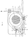
- a belt spool 12 is rotatably mounted between the side plates of a housing 10 of the belt retractor.
- the webbing 14 is wound on this belt reel 12.
- a control disk 16 which is provided with control teeth 18 on its outer circumference, can be rotated relative to the belt spool 12 to a relatively limited extent.
- the control disk 16 serves to activate a conventional locking mechanism, which is therefore not shown.
- the vehicle-sensitive activation of this locking mechanism takes place by a trigger pawl 20, which is schematically indicated in FIG. 1 and which rests on an inertia sensor in the form of a mass ball 22, being raised by movement of this inertia sensor and being displaced into the path of movement of the control teeth 18.
- control disk 16 is then prevented from rotating by the release pawl 20, so that a relative rotation between the control disk 16 and the belt reel 12 occurs when the webbing is further pulled off. This relative rotation is converted into an actuating movement by means of which a blocking bolt for blocking the belt spool 12 is activated. If the control disk 16 is equipped with a suitable inertia, it can also cause a webbing-sensitive locking by remaining behind the rotation of the belt reel 12 due to inertia.
- the existing control system for the vehicle-sensitive and / or webbing-sensitive locking mechanism is additionally used in the belt retractor according to the invention in order to give it a quasi-static blocking function.
- the webbing should only be able to be rolled up, but not pulled off, in order to be able to secure objects on a vehicle seat that are to be fixed immovably, for example loads or child seats.
- an additional control pawl 24 and a button 26 are required in the embodiment shown in FIG. 1: an additional control pawl 24 and a button 26.
- the additional control pawl 24 forms a two-armed lever which can be pivoted as well as by means of an elongated hole 27 on a pin 28 fixed to the housing is limitedly slidably mounted.
- the pawl tip 30 is formed on one lever arm 32, while the second lever arm 34 forms an actuating arm which interacts with the button 26.
- This button 26 is in turn designed as a two-armed lever and pivotally mounted on a pin 36 fixed to the housing.
- the first lever arm 38 is pressed elastically by a leaf spring 40 onto the outer circumference of the belt webbing, which is indicated in the drawing by the letter "B".
- the actuating arm 34 of the control pawl 24 engages with a lateral extension 34a behind the lever arm 38 of the button 26 and lies against one of its control surfaces, which is formed by the outside of this lever arm 38. Another control surface is formed on a side extension 42 of the lever arm 38.
- Another control surface of the button 26 is formed at the end of its second lever arm 44.
- the winding body of the belt spool 12 shown in section in FIG. 1 is provided on its outer circumference with a recess 46, into which the free end of the lever arm 38 of the button 26 can be partially immersed when the webbing is unwound.
- the control pawl 24 is spring-loaded by a tension spring 48 which is hooked onto the housing 10 at one end and engages with its other end in the vicinity of the pin 28 on the lever arm 34 of the control pawl 24 in such a way that the pawl tip 30 strives. to shift towards the outer periphery of the control disk 16. Nevertheless, the control pawl 24 is in a stable position out of engagement with the control teeth 18 of the control disk 16, as long as the button 26, as shown in FIG. 1 with solid lines, rests on a belt webbing winding B which has or exceeds a predetermined minimum outer diameter. In the embodiment shown, this minimum outer diameter is only exceeded when the webbing 14 has been completely unwound from the belt spool 12.
- the lever arm 38 is then in the position indicated by dashed lines in FIG. 1. In this position, the free end of the extension 42 of the lever arm 38 is raised far enough so that the extension 34a at the free end of the lever arm 34 can move clockwise beyond this extension 42. At the same time, the free end of the lever arm 44 has released the lever arm 34 of the control pawl 24. Under the action of the tension spring 48, the control pawl 24 is now pivoted clockwise until its pawl tip 30 enters the path of movement of the control teeth 18 on the outer circumference of the control disk 16. If a relative movement now occurs between the control disk 16 and the belt spool 12, the locking function becomes active. Belt strap 14 can therefore no longer be pulled off. On the other hand, the webbing 14 can be rolled up, since the pawl tip 30 and the control teeth 18 are so coordinated in their shape that a blocking effect only takes place in the webbing take-off direction.
- the webbing 14 is therefore first completely pulled off the belt spool 12. Only when the free end of the lever arm 38 in the Immersed recess 46, the control pawl 24 is released for control in the control teeth 18 on the outer circumference of the control disk 16. The webbing 14 is now placed around the object to be secured, the tongue is inserted into a buckle, and the webbing 14 is released so that it rolls up on the belt reel 12. The control pawl 24 is in a stable engagement position during this process, so that the quasi-static blocking function is maintained. In order to operate the belt retractor again with the vehicle-sensitive and / or belt-strap-sensitive locking function, the belt strap 14 is almost completely wound up until the outer diameter of the belt reel B has reached a predetermined intermediate value.
- the lever arm 38 of the button 26 is pivoted clockwise. So that the extension 34a at the end of the lever arm 34 of the control pawl 24 can spring back behind the extension 42 on the lever arm 38, a shift of the control pawl 24 must take place, in which the slot 27 serves as a guide.
- the buttons 26 and the control pawl 24 are again in the position shown in FIG. 1; In this state, the control pawl 24 is held in a stable position out of engagement with the control teeth 18 of the control disk 16 by the free end of the lever arm 44 resting against it and by the attachment of its extension 34a to the lever arm 38.
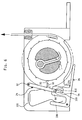
- the button 26 forms a two-armed lever, the lever arm 38 of which is elastically attached to the outer circumference of the belt webbing B by the leaf spring 40 is applied while the other lever arm is provided with a fork-shaped structure consisting of two fingers 50, 52 arranged at a distance from one another.
- a compression spring 56 is supported on the lever arm of the control pawl 24, which has the pawl tip 30 at its free end End supported on a control surface 58 of a design 60 fixed to the housing.
- This control surface 58 is designed so that the control pawl 24 is movable between two stable positions while overcoming an over-center position. In the first position, shown in solid lines in FIG. 2, the pawl tip 30 is out of engagement with the control teeth 18. In the second stable position, the pawl tip 30 engages in the path of movement of the control teeth 18. Between these two positions, the control pawl 24 is reversed via the fork-shaped structure, which is formed by the two fingers 50, 52 of the button 26 and cooperates with the actuating arm 54 of the control pawl 24.
- the control pawl 24 is basically of the same shape as in FIG. 2, but is under the action of a tension spring 64, which tends to move it into one of its two stable positions, overcoming a middle dead center position, which is defined by the direction of action of the spring 64 in relation to the position of the pivot axis of the control pawl 24.
- the spring 64 acts on the one hand on the free end of the actuating arm 54 and on the other hand on the housing 10 of the belt retractor.
- the two stable positions of the control pawl 24 are achieved by using a compression spring 70 in combination with an auxiliary lever 74 which can be pivoted about a pin 76 fixed to the housing and on which the compression spring 70 is supported at one end.
- the other end of the compression spring 70 is supported on a coupling pin 78 at the end of the actuating arm 54 of the control pawl 24.
- This coupling pin 78 engages in an elongated hole 80 at the free end of the auxiliary lever 74 so that the auxiliary lever 74 and the actuating arm 54 interact with one another in the manner of a toggle joint.
- the control pawl 24 is reversed between its two stable positions while overcoming a dead center position by means of a fork-shaped structure on one lever arm of the button 26.
- the button 26 is formed by a translationally movable stylus 80 which is guided on a housing-fixed guide structure 82 so as to be translationally movable in the direction of the belt reel B and away from it.
- the free end of the stylus 80 is held on the outer circumference of the belt reel B by a compression spring 82.
- the stylus 80 is provided with a laterally protruding actuating arm 84.
- the control pawl 24 is designed as a two-armed lever, the lever arm provided with the pawl tip 30 additionally carrying a first actuating arm 86.
- the other lever arm forms a second actuating arm 88. Both actuating arms 86, 88 cooperate with the actuating arm 34 of the stylus 80.
- the handling in this embodiment is the same as in the belt retractors according to FIGS. 1 and 2.
- control pawl 24 is designed as a one-armed lever which is pivotably mounted at one end on a bearing pin 92 fixed to the housing and carries a guide pin 94 at its free end.
- the pawl tip 30 is formed at the end of a side extension 96 of the control pawl 24.
- the guide pin 94 cooperates with a guide link of the button 26.
- This guide link is formed in a lateral arm 98 of the button 26.
- the boom 98 has a recess 100, the boundary surface of which forms a guide channel 104 with a resilient, resilient part 102.
- the guide pin 94 slides in this guideway 104, the shape of which is selected so that the button 26 moves the control pawl 24 in the desired manner and depending on the outer diameter of the belt reel B between its two stable positions.
- a leaf spring 106 clamped on the housing 10 presses with one end the control pawl 24 in the direction of its engagement position and with its other end against an arm 108 of the button 26 in order to place it elastically on the outer circumference of the belt reel B.
- the handling in this embodiment is the same as in the belt retractors described above.
Landscapes
- Engineering & Computer Science (AREA)
- Mechanical Engineering (AREA)
- Automotive Seat Belt Assembly (AREA)
Priority Applications (6)
| Application Number | Priority Date | Filing Date | Title |
|---|---|---|---|
| EP90103024A EP0442014B1 (de) | 1990-02-16 | 1990-02-16 | Gurtaufroller für Fahrzeug-Sicherheitsgurtsysteme |
| ES90103024T ES2027193T3 (es) | 1990-02-16 | 1990-02-16 | Enrollador de cinturon para sistemas de cinturones de seguridad de vehiculos. |
| DE59005369T DE59005369D1 (de) | 1990-02-16 | 1990-02-16 | Gurtaufroller für Fahrzeug-Sicherheitsgurtsysteme. |
| US07/656,231 US5176335A (en) | 1990-02-16 | 1991-02-14 | Belt retractor for vehicle safety belt systems |
| JP3022284A JPH0516763A (ja) | 1990-02-16 | 1991-02-15 | 車両安全ベルト系用ベルト引込装置 |
| JP000117U JPH0929U (ja) | 1990-02-16 | 1996-01-22 | 車両安全ベルト系用ベルト引込装置 |
Applications Claiming Priority (1)
| Application Number | Priority Date | Filing Date | Title |
|---|---|---|---|
| EP90103024A EP0442014B1 (de) | 1990-02-16 | 1990-02-16 | Gurtaufroller für Fahrzeug-Sicherheitsgurtsysteme |
Publications (2)
| Publication Number | Publication Date |
|---|---|
| EP0442014A1 EP0442014A1 (de) | 1991-08-21 |
| EP0442014B1 true EP0442014B1 (de) | 1994-04-13 |
Family
ID=8203656
Family Applications (1)
| Application Number | Title | Priority Date | Filing Date |
|---|---|---|---|
| EP90103024A Expired - Lifetime EP0442014B1 (de) | 1990-02-16 | 1990-02-16 | Gurtaufroller für Fahrzeug-Sicherheitsgurtsysteme |
Country Status (5)
| Country | Link |
|---|---|
| US (1) | US5176335A (ja) |
| EP (1) | EP0442014B1 (ja) |
| JP (2) | JPH0516763A (ja) |
| DE (1) | DE59005369D1 (ja) |
| ES (1) | ES2027193T3 (ja) |
Families Citing this family (7)
| Publication number | Priority date | Publication date | Assignee | Title |
|---|---|---|---|---|
| JPH045147A (ja) * | 1990-04-23 | 1992-01-09 | Takata Kk | シートベルト装置の作動機構 |
| DE9305244U1 (de) * | 1993-04-06 | 1993-06-09 | TRW Repa GmbH, 7077 Alfdorf | Anordnung zur Befestigung eines Gurtbandes an einer Welle eines Sicherheitsgurtaufrollers |
| DE29613044U1 (de) * | 1995-11-09 | 1996-11-07 | Trw Occupant Restraint Systems Gmbh, 73551 Alfdorf | Gurtaufroller für einen Fahrzeug-Sicherheitsgurt |
| DE19733343A1 (de) * | 1997-08-01 | 1999-02-04 | Takata Europ Gmbh | Gurtbandeinhängung |
| KR100645382B1 (ko) * | 2005-09-28 | 2006-11-14 | 델파이코리아 주식회사 | 좌석벨트용 리트랙터 |
| US8778360B2 (en) | 2005-10-27 | 2014-07-15 | University Of Notre Dame | Extracellular matrix cancer vaccine adjuvant |
| US8802113B2 (en) | 2005-10-27 | 2014-08-12 | University Of Notre Dame | Extracellular matrix cancer vaccine adjuvant |
Family Cites Families (12)
| Publication number | Priority date | Publication date | Assignee | Title |
|---|---|---|---|---|
| US3944163A (en) * | 1973-03-24 | 1976-03-16 | Kabushiki Kaisha Tokai Rika Denki Seisakusho | Seat belt retractor |
| US3858826A (en) * | 1973-08-23 | 1975-01-07 | Gen Motors Corp | Vehicle occupant restraint belt retractor |
| DE2821491C2 (de) * | 1978-05-17 | 1980-07-10 | Hugo Kern Und Liebers & Co Platinen- Und Federnfabrik, 7230 Schramberg | Vorrichtung zum automatischen Aufrollen von Sicherheitsgurten |
| JPS6058059B2 (ja) * | 1978-06-26 | 1985-12-18 | 株式会社高田工場 | ベルト巻取装置 |
| JPS57120046U (ja) * | 1981-01-20 | 1982-07-26 | ||
| JPS5943273A (ja) * | 1982-09-04 | 1984-03-10 | Kayaba Ind Co Ltd | カウンタ−バランスバルブ |
| JPS5935017B2 (ja) * | 1982-10-04 | 1984-08-25 | キヤノン株式会社 | 複写機の制御装置 |
| CA1221074A (en) * | 1982-11-29 | 1987-04-28 | Takayuki Ando | Webbing retractor |
| US4552319A (en) * | 1983-12-14 | 1985-11-12 | Irvin Industries Inc. | Combination VSI and ALR retractor |
| US4518132A (en) * | 1984-04-27 | 1985-05-21 | General Safety Corporation | Combination seat belt retractor mechanism |
| US4537363A (en) * | 1984-08-30 | 1985-08-27 | Allied Corporation | Lock-up mechanism for a vehicle sensitive automotive seat belt retractor |
| US4729524A (en) * | 1986-09-26 | 1988-03-08 | Trw Vehicle Safety Systems Limited | Seat belt retractor with cinch mechanism |
-
1990
- 1990-02-16 DE DE59005369T patent/DE59005369D1/de not_active Expired - Fee Related
- 1990-02-16 EP EP90103024A patent/EP0442014B1/de not_active Expired - Lifetime
- 1990-02-16 ES ES90103024T patent/ES2027193T3/es not_active Expired - Lifetime
-
1991
- 1991-02-14 US US07/656,231 patent/US5176335A/en not_active Expired - Fee Related
- 1991-02-15 JP JP3022284A patent/JPH0516763A/ja active Pending
-
1996
- 1996-01-22 JP JP000117U patent/JPH0929U/ja active Pending
Also Published As
| Publication number | Publication date |
|---|---|
| ES2027193T3 (es) | 1994-08-16 |
| US5176335A (en) | 1993-01-05 |
| DE59005369D1 (de) | 1994-05-19 |
| JPH0516763A (ja) | 1993-01-26 |
| EP0442014A1 (de) | 1991-08-21 |
| ES2027193T1 (es) | 1992-06-01 |
| JPH0929U (ja) | 1997-01-17 |
Similar Documents
| Publication | Publication Date | Title |
|---|---|---|
| DE10027134B4 (de) | Rückziehvorrichtung für einen Fahrzeugsicherheitsgurt | |
| EP0485656A1 (de) | Schloss für Sicherheitsgurtsysteme in Fahrzeugen | |
| EP0376320A1 (de) | Höhenverstellbarer Umlenkbeschlag für Sicherheitsgurte von Kraftfahrzeugen | |
| EP0865975B1 (de) | Gurtaufroller für einen Fahrzeug-Sicherheitsgurt | |
| EP0442014B1 (de) | Gurtaufroller für Fahrzeug-Sicherheitsgurtsysteme | |
| DE29704974U9 (de) | Gurtaufroller für einen Fahrzeug-Sicherheitsgurt | |
| DE3049564C2 (ja) | ||
| DE3446981A1 (de) | Klemmvorrichtung fuer ein sicherheitsgurtsystem | |
| DE3933453A1 (de) | Gurtaufroller | |
| DE3913631A1 (de) | Gurtaufroller mit deblockiereinrichtung | |
| DE3034074A1 (de) | Einzugseinrichtung fuer anschnallgurt | |
| EP0557983A1 (de) | Sicherheitsgurtschloss mit Verriegelungssperre | |
| DE3509254A1 (de) | Sicherheitsgurtaufroller | |
| DE4137029C2 (de) | Fahrzeugsitzgurt-Rückholvorrichtung | |
| DE4444655C2 (de) | Sicherheitsgurt-Blockiereinrichtung mit Selbstblockadeverhinderung | |
| DE2425049C3 (de) | Aufrollmechanismus, insbesondere für Sicherheitsgurte in Kraftfahrzeugen | |
| DE2917197A1 (de) | Rueckspulvorrichtung fuer sicherheitsgurte | |
| DE2821152A1 (de) | Aufwickelvorrichtung fuer sicherheitsgurte von fahrzeugen, insbesondere personenkraftfahrzeugen | |
| DE19508620C2 (de) | Sicherheitsgurt-Rückhaltesystem mit Auslösesicherung für mechanischen Sensor | |
| DE9202525U1 (de) | Sicherheitsgurtschloß mit Verriegelungssperre | |
| DE2736998A1 (de) | Aufwickelvorrichtung fuer sicherheitsgurte | |
| DE19602178C1 (de) | Elektrisch gesteuerter Sicherheitsgurtaufroller mit Stromsparschaltung | |
| DE19539439C2 (de) | Klemmvorrichtung | |
| DE102008009771B4 (de) | Gurtaufroller für einen Fahrzeug-Sicherheitsgurt | |
| DE10358561A1 (de) | Gurtaufroller für einen Fahrzeug-Sicherheitsgurt |
Legal Events
| Date | Code | Title | Description |
|---|---|---|---|
| PUAI | Public reference made under article 153(3) epc to a published international application that has entered the european phase |
Free format text: ORIGINAL CODE: 0009012 |
|
| AK | Designated contracting states |
Kind code of ref document: A1 Designated state(s): AT BE CH DE DK ES FR GB GR IT LI LU NL SE |
|
| RBV | Designated contracting states (corrected) |
Designated state(s): DE ES FR GB IT SE |
|
| GBC | Gb: translation of claims filed (gb section 78(7)/1977) | ||
| EL | Fr: translation of claims filed | ||
| 17P | Request for examination filed |
Effective date: 19911205 |
|
| 17Q | First examination report despatched |
Effective date: 19930407 |
|
| GRAA | (expected) grant |
Free format text: ORIGINAL CODE: 0009210 |
|
| AK | Designated contracting states |
Kind code of ref document: B1 Designated state(s): DE ES FR GB IT SE |
|
| GBT | Gb: translation of ep patent filed (gb section 77(6)(a)/1977) |
Effective date: 19940420 |
|
| REF | Corresponds to: |
Ref document number: 59005369 Country of ref document: DE Date of ref document: 19940519 |
|
| ITF | It: translation for a ep patent filed | ||
| ET | Fr: translation filed | ||
| REG | Reference to a national code |
Ref country code: ES Ref legal event code: FG2A Ref document number: 2027193 Country of ref document: ES Kind code of ref document: T3 |
|
| PGFP | Annual fee paid to national office [announced via postgrant information from national office to epo] |
Ref country code: SE Payment date: 19950109 Year of fee payment: 6 |
|
| PGFP | Annual fee paid to national office [announced via postgrant information from national office to epo] |
Ref country code: FR Payment date: 19950127 Year of fee payment: 6 |
|
| EAL | Se: european patent in force in sweden |
Ref document number: 90103024.7 |
|
| PGFP | Annual fee paid to national office [announced via postgrant information from national office to epo] |
Ref country code: GB Payment date: 19950207 Year of fee payment: 6 |
|
| PGFP | Annual fee paid to national office [announced via postgrant information from national office to epo] |
Ref country code: ES Payment date: 19950216 Year of fee payment: 6 |
|
| PLBE | No opposition filed within time limit |
Free format text: ORIGINAL CODE: 0009261 |
|
| STAA | Information on the status of an ep patent application or granted ep patent |
Free format text: STATUS: NO OPPOSITION FILED WITHIN TIME LIMIT |
|
| PGFP | Annual fee paid to national office [announced via postgrant information from national office to epo] |
Ref country code: DE Payment date: 19950307 Year of fee payment: 6 |
|
| 26N | No opposition filed | ||
| PG25 | Lapsed in a contracting state [announced via postgrant information from national office to epo] |
Ref country code: GB Effective date: 19960216 |
|
| PG25 | Lapsed in a contracting state [announced via postgrant information from national office to epo] |
Ref country code: SE Effective date: 19960217 Ref country code: ES Free format text: LAPSE BECAUSE OF NON-PAYMENT OF DUE FEES Effective date: 19960217 |
|
| GBPC | Gb: european patent ceased through non-payment of renewal fee |
Effective date: 19960216 |
|
| PG25 | Lapsed in a contracting state [announced via postgrant information from national office to epo] |
Ref country code: FR Effective date: 19961031 |
|
| PG25 | Lapsed in a contracting state [announced via postgrant information from national office to epo] |
Ref country code: DE Effective date: 19961101 |
|
| REG | Reference to a national code |
Ref country code: FR Ref legal event code: ST |
|
| REG | Reference to a national code |
Ref country code: ES Ref legal event code: FD2A Effective date: 19990503 |
|
| PG25 | Lapsed in a contracting state [announced via postgrant information from national office to epo] |
Ref country code: IT Free format text: LAPSE BECAUSE OF NON-PAYMENT OF DUE FEES;WARNING: LAPSES OF ITALIAN PATENTS WITH EFFECTIVE DATE BEFORE 2007 MAY HAVE OCCURRED AT ANY TIME BEFORE 2007. THE CORRECT EFFECTIVE DATE MAY BE DIFFERENT FROM THE ONE RECORDED. Effective date: 20050216 |