EP0441611A1 - Magnetooptischer Aufzeichnungsträger und Verfahren zur Bearbeitung seiner Oberfläche - Google Patents
Magnetooptischer Aufzeichnungsträger und Verfahren zur Bearbeitung seiner Oberfläche Download PDFInfo
- Publication number
- EP0441611A1 EP0441611A1 EP91300969A EP91300969A EP0441611A1 EP 0441611 A1 EP0441611 A1 EP 0441611A1 EP 91300969 A EP91300969 A EP 91300969A EP 91300969 A EP91300969 A EP 91300969A EP 0441611 A1 EP0441611 A1 EP 0441611A1
- Authority
- EP
- European Patent Office
- Prior art keywords
- magneto
- recording medium
- optical recording
- recessions
- protrusions
- Prior art date
- Legal status (The legal status is an assumption and is not a legal conclusion. Google has not performed a legal analysis and makes no representation as to the accuracy of the status listed.)
- Granted
Links
Images


Classifications
-
- G—PHYSICS
- G11—INFORMATION STORAGE
- G11B—INFORMATION STORAGE BASED ON RELATIVE MOVEMENT BETWEEN RECORD CARRIER AND TRANSDUCER
- G11B5/00—Recording by magnetisation or demagnetisation of a record carrier; Reproducing by magnetic means; Record carriers therefor
- G11B5/48—Disposition or mounting of heads or head supports relative to record carriers ; arrangements of heads, e.g. for scanning the record carrier to increase the relative speed
- G11B5/58—Disposition or mounting of heads or head supports relative to record carriers ; arrangements of heads, e.g. for scanning the record carrier to increase the relative speed with provision for moving the head for the purpose of maintaining alignment of the head relative to the record carrier during transducing operation, e.g. to compensate for surface irregularities of the latter or for track following
- G11B5/60—Fluid-dynamic spacing of heads from record-carriers
- G11B5/6005—Specially adapted for spacing from a rotating disc using a fluid cushion
-
- G—PHYSICS
- G11—INFORMATION STORAGE
- G11B—INFORMATION STORAGE BASED ON RELATIVE MOVEMENT BETWEEN RECORD CARRIER AND TRANSDUCER
- G11B11/00—Recording on or reproducing from the same record carrier wherein for these two operations the methods are covered by different main groups of groups G11B3/00 - G11B7/00 or by different subgroups of group G11B9/00; Record carriers therefor
- G11B11/10—Recording on or reproducing from the same record carrier wherein for these two operations the methods are covered by different main groups of groups G11B3/00 - G11B7/00 or by different subgroups of group G11B9/00; Record carriers therefor using recording by magnetic means or other means for magnetisation or demagnetisation of a record carrier, e.g. light induced spin magnetisation; Demagnetisation by thermal or stress means in the presence or not of an orienting magnetic field
- G11B11/105—Recording on or reproducing from the same record carrier wherein for these two operations the methods are covered by different main groups of groups G11B3/00 - G11B7/00 or by different subgroups of group G11B9/00; Record carriers therefor using recording by magnetic means or other means for magnetisation or demagnetisation of a record carrier, e.g. light induced spin magnetisation; Demagnetisation by thermal or stress means in the presence or not of an orienting magnetic field using a beam of light or a magnetic field for recording by change of magnetisation and a beam of light for reproducing, i.e. magneto-optical, e.g. light-induced thermomagnetic recording, spin magnetisation recording, Kerr or Faraday effect reproducing
- G11B11/1055—Disposition or mounting of transducers relative to record carriers
- G11B11/1058—Flying heads
-
- G—PHYSICS
- G11—INFORMATION STORAGE
- G11B—INFORMATION STORAGE BASED ON RELATIVE MOVEMENT BETWEEN RECORD CARRIER AND TRANSDUCER
- G11B11/00—Recording on or reproducing from the same record carrier wherein for these two operations the methods are covered by different main groups of groups G11B3/00 - G11B7/00 or by different subgroups of group G11B9/00; Record carriers therefor
- G11B11/10—Recording on or reproducing from the same record carrier wherein for these two operations the methods are covered by different main groups of groups G11B3/00 - G11B7/00 or by different subgroups of group G11B9/00; Record carriers therefor using recording by magnetic means or other means for magnetisation or demagnetisation of a record carrier, e.g. light induced spin magnetisation; Demagnetisation by thermal or stress means in the presence or not of an orienting magnetic field
- G11B11/105—Recording on or reproducing from the same record carrier wherein for these two operations the methods are covered by different main groups of groups G11B3/00 - G11B7/00 or by different subgroups of group G11B9/00; Record carriers therefor using recording by magnetic means or other means for magnetisation or demagnetisation of a record carrier, e.g. light induced spin magnetisation; Demagnetisation by thermal or stress means in the presence or not of an orienting magnetic field using a beam of light or a magnetic field for recording by change of magnetisation and a beam of light for reproducing, i.e. magneto-optical, e.g. light-induced thermomagnetic recording, spin magnetisation recording, Kerr or Faraday effect reproducing
- G11B11/10582—Record carriers characterised by the selection of the material or by the structure or form
- G11B11/10584—Record carriers characterised by the selection of the material or by the structure or form characterised by the form, e.g. comprising mechanical protection elements
-
- Y—GENERAL TAGGING OF NEW TECHNOLOGICAL DEVELOPMENTS; GENERAL TAGGING OF CROSS-SECTIONAL TECHNOLOGIES SPANNING OVER SEVERAL SECTIONS OF THE IPC; TECHNICAL SUBJECTS COVERED BY FORMER USPC CROSS-REFERENCE ART COLLECTIONS [XRACs] AND DIGESTS
- Y10—TECHNICAL SUBJECTS COVERED BY FORMER USPC
- Y10S—TECHNICAL SUBJECTS COVERED BY FORMER USPC CROSS-REFERENCE ART COLLECTIONS [XRACs] AND DIGESTS
- Y10S428/00—Stock material or miscellaneous articles
- Y10S428/90—Magnetic feature
-
- Y—GENERAL TAGGING OF NEW TECHNOLOGICAL DEVELOPMENTS; GENERAL TAGGING OF CROSS-SECTIONAL TECHNOLOGIES SPANNING OVER SEVERAL SECTIONS OF THE IPC; TECHNICAL SUBJECTS COVERED BY FORMER USPC CROSS-REFERENCE ART COLLECTIONS [XRACs] AND DIGESTS
- Y10—TECHNICAL SUBJECTS COVERED BY FORMER USPC
- Y10S—TECHNICAL SUBJECTS COVERED BY FORMER USPC CROSS-REFERENCE ART COLLECTIONS [XRACs] AND DIGESTS
- Y10S428/00—Stock material or miscellaneous articles
- Y10S428/922—Static electricity metal bleed-off metallic stock
- Y10S428/9265—Special properties
- Y10S428/928—Magnetic property
-
- Y—GENERAL TAGGING OF NEW TECHNOLOGICAL DEVELOPMENTS; GENERAL TAGGING OF CROSS-SECTIONAL TECHNOLOGIES SPANNING OVER SEVERAL SECTIONS OF THE IPC; TECHNICAL SUBJECTS COVERED BY FORMER USPC CROSS-REFERENCE ART COLLECTIONS [XRACs] AND DIGESTS
- Y10—TECHNICAL SUBJECTS COVERED BY FORMER USPC
- Y10T—TECHNICAL SUBJECTS COVERED BY FORMER US CLASSIFICATION
- Y10T428/00—Stock material or miscellaneous articles
- Y10T428/21—Circular sheet or circular blank
- Y10T428/218—Aperture containing
-
- Y—GENERAL TAGGING OF NEW TECHNOLOGICAL DEVELOPMENTS; GENERAL TAGGING OF CROSS-SECTIONAL TECHNOLOGIES SPANNING OVER SEVERAL SECTIONS OF THE IPC; TECHNICAL SUBJECTS COVERED BY FORMER USPC CROSS-REFERENCE ART COLLECTIONS [XRACs] AND DIGESTS
- Y10—TECHNICAL SUBJECTS COVERED BY FORMER USPC
- Y10T—TECHNICAL SUBJECTS COVERED BY FORMER US CLASSIFICATION
- Y10T428/00—Stock material or miscellaneous articles
- Y10T428/24—Structurally defined web or sheet [e.g., overall dimension, etc.]
- Y10T428/24355—Continuous and nonuniform or irregular surface on layer or component [e.g., roofing, etc.]
-
- Y—GENERAL TAGGING OF NEW TECHNOLOGICAL DEVELOPMENTS; GENERAL TAGGING OF CROSS-SECTIONAL TECHNOLOGIES SPANNING OVER SEVERAL SECTIONS OF THE IPC; TECHNICAL SUBJECTS COVERED BY FORMER USPC CROSS-REFERENCE ART COLLECTIONS [XRACs] AND DIGESTS
- Y10—TECHNICAL SUBJECTS COVERED BY FORMER USPC
- Y10T—TECHNICAL SUBJECTS COVERED BY FORMER US CLASSIFICATION
- Y10T428/00—Stock material or miscellaneous articles
- Y10T428/31504—Composite [nonstructural laminate]
- Y10T428/31855—Of addition polymer from unsaturated monomers
- Y10T428/31935—Ester, halide or nitrile of addition polymer
Definitions
- the present invention relates to a magneto-optical recording medium to be used with a magneto-optical recording/reproducing device comprising a floating type magnetic head, and to a method for processing the surface of the magneto-optical recording medium.
- a substrate made of glass, plastic, ceramic or other material and coated with a vertically magnetized film composed of metal magnetic material serves as a recording medium, and recording and reproducing operations on and from the recording medium are carried out in the following process.
- the magnetization direction of the vertically magnetized film of the recording medium is arranged to a predetermined direction (upward direction or downward direction) by using a strong external magnetic field or the like (hereinafter this process is referred to as initialization). Then the temperature of a recording portion where the recording is to be carried out is raised to exceed the vicinity of the Curie point or is raised to exceed its magnetic compensation point by projecting a laser beam on the recording portion. As a result, the magnetic coercive force (Hc) on the recording portion becomes zero or substantially zero. With this state, the magnetization direction is reversed by applying an external magnetic field (bias magnetic field) whose magnetization direction is opposite to the initialized magnetization direction. When the projection of the laser beam is stopped, the recording portion of the recording medium returns to room temperature. Thus, since the reversed magnetization direction is fixed, information is recorded.
- the above-mentioned recording operation is also called thermomagnetic recording.
- a linearly polarized laser beam is projected onto the recording medium.
- the rotating direction of a polarization plane of reflected light or transmitted light from or through the recording medium varies according to the magnetization direction (upward or downward) of the recording medium (this is called magnetic Kerr effect or magnetic Faraday effect).
- Information is optically read out by the use of the magnetic effect.
- method (ii) improving the recording medium, it is difficult to control recording medium composition, film thickness and so on.
- the most effective means is improving the external magnetic field generating device of method (ii), i.e. switching a direction of the external magnetic field at high speed according to information signals while keeping the intensity of the laser beam constant.
- a magnetic head (a coil and a coil core) of the external magnetic field generating device In order to switch the direction of the external magnetic field at high speed, a magnetic head (a coil and a coil core) of the external magnetic field generating device must be miniaturized to a great degree. In this case, however, a generating area of the magnetic field becomes smaller. In order to counteract this, a magnetic head and a recording medium must be brought closer to each other.
- a floating head 32 of a sliding type which can glide over a recording medium in the shape of a disc (not shown) is employed as the external magnetic field generating device.
- the floating head 32 comprises a slider section 33 provided with a magnetic head section 34. The floating head 32 is pressed down toward the recording medium and supported by a suspension 31. According to the configuration, when the recording medium is rotated, the floating head 32 floats over the surface of the recording medium.
- a constant floating height of the floating head 32 is maintained due to the fact that floating force balances with depressing force.
- the floating force is exerted upwards on the slider section 33 by the air flowing between the slider section 33 and the recording medium.
- the depressing force is exerted downwards on the slider section 33 by the suspension 31.
- the floating head of this type is also used for conventional hard disks of magnetic recording/reproducing devices.
- the floating height is of a submicron order.
- the recording medium is a magneto-optical disk
- a floating height of 5 ⁇ m to 15 ⁇ m is necessary, i.e. a larger floating height is needed for the magneto-optical disk than for the hard disk.
- the reasons for this are as follows. Since the magneto-optical disks are transportable, dust tends to stick more frequently on the disk. As a result, troubles such as a head crash, where the magneto-optical head 34 is damaged by dust as the floating height is too small, may occur.
- a texture tape 36 having fine protrusions and recessions on the surface thereof is used. More precisely, when forming the disk surface with the texture, the texture tape 36 is pressed onto a magneto-optical disk 35 by a tape pressure roller 37 and then the magneto-optical disk 35 is rotated while feeding the texture tape in the direction of arrow C.
- the floating height of the floating head is 5 ⁇ m to 15 ⁇ m, greater than a floating height required when a hard disk is used. Therefore, variations in the floating height greatly depend on the relative velocity between the magneto-optical disk and the floating head.
- Table 1 The relation is shown in Table 1 below. Referring to Table 1, if depressing force F of the suspension is constant and the relative velocity increases by two times, the floating height increases by a substantial one and half times (here, the dimensions of the slider section are 6mm x 4mm).
- the relative velocity is higher in outer parts of the magneto-optical disk than in inner parts thereof, resulting in a higher floating height in the outer parts. Consequently, a magnetic field intensity applied to the magneto-optical disk by the floating head varies at each radial locations on the magneto-optical disk, and therefore a problem arises, i.e. the recording operation with a conventional magneto-optical disk cannot be carried out under constant conditions.
- a floating type magnetic head hereinafter referred to as a floating head
- a constant floating height of the floating head is maintained irrespective of radial locations on the magneto-optical disk.
- a magneto-optical recording medium of the present invention is characterized in that the shapes of fine and physical protrusions and recessions formed on the surface of the magneto-optical recording medium vary at each radial locations on the magneto-optical recording medium.
- the average orientation of the respective protrusions and recessions with respect to their lengths crosses the rotating direction of the recording medium at substantially right angle in inner parts of the recording medium and is substantially in parallel with the rotating direction in outer parts thereof.
- the physical protrusions and recessions are formed such that the maximum value R MAX of their heights is larger in the inner parts than in the outer parts, i.e. rough protrusions and recessions are formed in the inner parts while fine protrusions and recessions are formed in the outer parts.
- a method for processing the surface of a magneto-optical recording medium relating to the present invention may be adopted, wherein a tape having a surface whereon fine and physical protrusions and recessions are formed is used.
- fine and physical protrusions and recessions to be formed on the surface of the recording medium by pressing the tape onto the recording medium with pressure means and moving the pressure means are respectively aligned in a direction which crosses the rotating direction of a recording medium at substantially right-angle in the inner parts and is in parallel with the rotating direction of the medium in the outer parts.
- Another method for processing the surface of a magneto-optical recording medium relating to the present invention is characterized in that a tape whose roughness is large is used in the inner parts of the recording medium and a tape whose roughness is small is used in the outer parts thereof so as to form rough protrusions and recessions in the inner parts and fine protrusions and recessions in the outer parts.
- the depressing force of the pressure means may be strengthened in the inner parts while it may be weakened in the outer parts.
- Another method for processing the surface of a magneto-optical recording medium is characterized in that by using a stamper whereon fine and physical protrusions and recessions corresponding to desired shapes to be formed on the recording medium are etched, the protrusions and recessions of the desired shapes are copied on the surface of the recording medium.
- the shape of protrusions and recessions formed on the surface of the recording medium varies from the inner parts of the recording medium toward the outer parts thereof.
- force hereinafter referred to as floating force
- floating force floating force
- the floating force in the inner parts becomes equal to the floating force in the outer parts. Therefore, even when the relative velocity between the floating head and the recording medium changes due to the rotation of the magneto-optical recording medium in the CAV method, the floating height of the floating head does not vary. As a result, the recording condition is maintained to be constant irrespective of the locations on the recording medium in a radial direction, thereby permitting the accuracy of the recording to improve.
- the method using a stamper can be adopted for the mass production of magneto-optical recording media having the above-mentioned characteristics.
- Figs. 1 to 3 show one embodiment of the present invention.
- Fig. 1 is a schematic longitudinal sectional view showing the structure of a magneto-optical disk.
- Fig. 2 is a typical plan depiction showing the features of the texture of the magneto-optical disk surface.
- Fig. 3(a) and Fig. 3(b) are explanatory views showing a method for forming the recording medium surface with the texture.
- Fig. 4 and Fig. 5 show another embodiment of the present invention.
- Fig. 4 is a schematic longitudinal sectional view showing the structure of a magneto-optical disk.
- Fig. 5 is a typical schematic plan depiction showing the features of textures of the magneto-optical disk surface.
- Fig. 6 to Fig. 9 show another embodiment of the present invention.
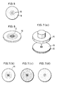
- Fig. 6 is a typical schematic perspective depiction showing the features of the texture of a magneto-optical disk surface.
- Fig. 7(a) is a schematic perspective view showing a method for forming the magneto-optical disk surface with the texture by the use of a stamper.
- Fig. 7(b) to Fig. 7(d) are typical schematic bottom plan depictions showing the features of textures etched on the stamper, corresponding to the features of textures of a recording medium to be formed.
- Fig. 8 and Fig. 9 are schematic perspective views showing a method for mass-producing the texture by the use of stampers.
- Fig. 10(a) is a schematic perspective view showing a floating head and a suspension.
- Fig. 10(b) is a perspective view showing the floating head.
- Fig. 11 and Fig. 12 show a conventional example.
- Fig. 11(a) and Fig. 11(b) are explanatory views showing a method for forming a magneto-optical disk surface with a texture by using a texture tape.
- Fig. 12 is a typical plan depiction showing the features of the texture of the magneto-optical disk surface.
- a magneto-optical disk as a magneto-optical recording medium of the present invention is configured such that a substrate 1, a magneto-optical recording film 2 and a protective film 3 are laminated in order.
- the substrate 1 is made of an optically transparent material such as glass, polycarbonate, polymethyl methacrylate and amolphous polyolefine.
- the magneto-optical recording film 2 of single-layer structure or multilayer structure including a dielectric film, reflection film and the like, is formed on the substrate 1 by sputtering, evaporation or other process.
- the protective film 3 formed on the magneto-optical recording film 2 it is made of an organic arterial such as UV hardening resin or an inorganic material such as SiO2, carbon and ceramic.
- Fine and physical protrusions and recessions forming a texture 4 are formed on the surface of the protective film 3.
- the process for giving the texture 4 to the surface of a magneto-optical disk is called the surface processing.
- the protrusions and recessions forming the texture 4 are aligned in a direction which crosses the rotating direction of the disk at substantially right angle in inner parts of the disk, while they are aligned in a direction which is substantially in parallel with the rotating direction of the disk in outer parts thereof.
- the average orientation of the respective physical protrusions and recessions with respect to their lengths varies successively so that it crosses the rotating direction of the disk at substantially right angle in the inner parts of the disk and it is substantially in parallel with the rotating direction in the outer parts thereof.
- the fine and physical protrusions and recessions are formed on the surface of the magneto-optical disk in different directions at respective radial locations. Accordingly, floating force given to a floating head from the magneto-optical disk being rotated based on the CAV method through an air layer becomes the same in both in the inner parts and in the outer parts. Consequently, the floating height of the floating head becomes constant irrespective of radial locations on the magneto-optical disk.
- a texture tape 6 having fine and physical protrusions and recessions on its surface is used for forming the texture 4.
- the texture tape 6 is pressed onto the surface of the disk 5 by a pressure roller 7 as pressure means and then the texture tape 6 is fed to the direction of arrow A shown in Fig. 3(a) while rotating the disk 5.
- the pressure roller 7 is moved toward the inner parts from the outer parts, i.e. toward the position of Fig. 3(b) from the position of Fig.
- the protrusions and recessions forming the texture 4 are formed on the surface of the magneto-optical disk 5 in clockwise, but they may be formed in counterclockwise.
- a magneto-optical disk of the present embodiment comprises a substrate 1, a magneto-optical recording film 2 and a protective film 3.
- Protrusions and recessions forming textures 8 and 9 are formed on the surface of the protective film 3.
- mainly rough protrusions and recessions forming the texture 8 are formed in inner parts of the disk, while mainly fine protrusions and recessions forming the texture 9 are formed in outer parts of the disk.
- the maximum value R MAX for the heights of the rough protrusions and recessions is 100nm to 2500nm, and the maximum value R MAX for the heights of the fine protrusions and recessions is not more than 200nm.
- the area of the fine texture 9 and the area of the rough texture 8 are indicated distinguishably so that the features of the disk surface are easily understood.
- the protrusions and recessions can be formed such that each of the protrusions and recessions becomes smaller gradually from the inner parts toward the outer parts of the disk according to the relative velocity between the magneto-optical disk and the floating head.
- the shapes of the fine and physical protrusions and recessions formed on the surface of the protective film 3 vary at each radial locations on the disk.
- a texture tape of a large roughness is pressed onto the inner parts of the disk surface by the pressure roller and like the conventional cases the texture tape is fed while rotating the disk. With this operation, rough protrusions and recessions form the texture 8.
- a texture tape having a small roughness is used in the outer parts of the disk. Therefore, fine protrusions and recessions forming the texture 9 are formed in the outer parts in the same way as the way for the inner parts.
- tapes having the same roughness may be employed instead of using texture tapes having different conditions each other in roughness in the inner parts and the outer parts of the disk.
- the depressing force of the pressure roller is strengthened in the inner parts and is weakened in the outer parts so that rough protrusions and recessions are formed in the inner parts and fine protrusions and recessions are formed in the outer parts.
- a magneto-optical disk of the present embodiment is configured such that a magneto-optical recording film, and a protective film are laminated on a substrate.
- a resin layer 10 is formed on the protective film, and protrusions and recessions 11 in the shape of folds and having the maximum heights R MAX of 100nm to 2500nm are formed on the surface of the resin layer 10.
- the protrusions and recessions 11 are formed such that lines representing the tops of each folds extend radially in radial directions of the magneto-optical disk.
- the height of the fold decreases gradually from inner parts of the disk toward outer parts thereof. That is to say, the shapes of the physical protrusions and recessions formed on the surface of the resin layer 10 vary at each radial locations on the magneto-optical disk.
- the floating force given to a floating head from the magneto-optical disk being rotated based on the CAV method through an air layer becomes the same both in the inner parts and in the outer parts, the floating height of the floating head becomes constant irrespective of radial locations on the magneto-optical disk.
- the magneto-optical disk 12 is coated with a resin 13 made of an ultra violet (UV) hardening resin (for example, unsaturated polyester and oligoacrylate).
- the UV hardening resin is a kind of optical hardening resins.
- the resin 13 is hardened by irradiating ultra violet light thereon.
- a stamper 14 whose texture corresponds to the protrusions and recessions 11 in the shape of folds is pressed onto the hardened resin 13.
- the bottom surface of the stamper 14 is textured with desired features, for example the one shown in Fig. 7(b), by chemical etching, precision machine processing or other process.
- the features of a texture to be etched on the stamper 14 may correspond to the features of the textures discussed in the first embodiment and the second embodiment, shown in Fig. 7(c) and Fig. 7(d). In such cases, a magneto-optical disk having the texture features discussed in the first embodiment or the second embodiment can be formed.
- magneto-optical disks 15 are produced on a production board 18 by leaving predetermined spaces longitudinally and transversely between the disks.
- the magneto-optical disks 15 have already been coated with a resin (not shown).
- a roller 16 comprises stampers 17 for giving texture.
- the stampers 17 are positioned so as to correspond to the respective magneto-optical disks 15.
- the roller 16 is rotated and the stampers 17 for giving texture are pressed onto the magneto-optical disks 15 on the production board 18 with constant pressure P, so that the magneto-optical disks 15 having a texture of desired features can be produced.
- magneto-optical disks 19 are formed on a production board 24, and a roller 20 comprises stampers 21 on the surface thereof.
- a pot 22 containing a thermoplastic resin 23 is disposed above the roller 20.
- the resin 23 is supplied to the roller 20 from the bottom section of the pot 22.
- the magneto-optical disks 19 are not coated with a resin for giving texture.
- the resin 23 is supplied to each the stampers 21 from the bottom section of the pot 22 at the time the roller 20 rolls on the production board 24.
- the resin 23 whereon the features of the texture of the stampers 21 are transferred is applied to the magneto-optical disks 19 with the rolling of the roller 20.
- the stampers 21 and the pot 22 are heated. Since the resin 23 is a thermoplastic resin, the resin 23 attached on the magneto-optical disks 19 are hardened by being cooled. Consequently, the surfaces of the magneto-optical disks 19 are textured with desired features.
- a magneto-optical recording medium of the present invention is basically configured such that the shapes of fine and physical protrusions and recessions formed on the surface of the medium vary at each radial locations on the magneto-optical recording medium.
- the relative velocity between the floating head and the magneto-optical recording medium becomes higher toward the outer parts.
- the floating pressure in the outer parts equals the floating pressure in the inner parts due to the shapes of protrusions and recessions formed on the surface of the recording medium. Therefore, the floating height of the floating head is substantially constant irrespective of radial locations on the recording medium. Consequently, since the intensity of the magnetic field applied to the magneto-optical recording medium from the floating head becomes substantially constant, information is recorded under substantially constant conditions irrespective of radial locations, thereby permitting the accuracy of the recording to improve.
- a method for processing the surface of a magneto-optical recording medium relating to the present invention is characterized in that pressure means is moved so that protrusions and recessions are formed in a direction which crosses the rotating direction of the recording medium at substantially right angle in inner parts of the recording medium and is in parallel with the rotating direction in outer parts thereof.
- Another method for processing the surface of a magneto-optical recording medium relating to the present invention is characterized in that a tape whose roughness is large is used in inner parts of the recording medium while a tape whose roughness is small is used in outer parts thereof.
- Another method for processing the surface of a magneto-optical recording medium relating to the present invention is characterized in that the depressing force of pressure means is strong in inner parts of the recording medium while it is weak in outer parts thereof.
- Another method for processing the surface of a magneto-optical recording medium relating to the present invention is characterized in that protrusions and recessions of desired shapes are formed by using a stamper whereon the desired shapes are etched beforehand and by copying the shapes onto the surface of the magneto-optical recording medium.
- magneto-optical recording media produced based on the above methods are characterized in that the shapes of fine and physical protrusions and recessions formed on the surface of the magneto-optical recording media vary at each radial locations on the magneto-optical recording media. Therefore, the respective methods are capable of producing magneto-optical recording media on which information is recorded under substantially constant conditions irrespective of the position of a floating head in a radial direction of the recording media.
Applications Claiming Priority (2)
| Application Number | Priority Date | Filing Date | Title |
|---|---|---|---|
| JP2026477A JP2600004B2 (ja) | 1990-02-06 | 1990-02-06 | 光磁気記録媒体及びその表面処理方法 |
| JP26477/90 | 1990-02-06 |
Publications (2)
| Publication Number | Publication Date |
|---|---|
| EP0441611A1 true EP0441611A1 (de) | 1991-08-14 |
| EP0441611B1 EP0441611B1 (de) | 1996-06-19 |
Family
ID=12194585
Family Applications (1)
| Application Number | Title | Priority Date | Filing Date |
|---|---|---|---|
| EP91300969A Expired - Lifetime EP0441611B1 (de) | 1990-02-06 | 1991-02-06 | Magnetooptischer Aufzeichnungsträger und Verfahren zur Bearbeitung seiner Oberfläche |
Country Status (5)
| Country | Link |
|---|---|
| US (2) | US5328740A (de) |
| EP (1) | EP0441611B1 (de) |
| JP (1) | JP2600004B2 (de) |
| CA (1) | CA2035410C (de) |
| DE (1) | DE69120308T2 (de) |
Cited By (6)
| Publication number | Priority date | Publication date | Assignee | Title |
|---|---|---|---|---|
| EP0535577A2 (de) * | 1991-09-30 | 1993-04-07 | Sony Corporation | Magneto-optisches Scheibensystem und magneto-optische Scheibe dafür |
| US5231613A (en) * | 1990-01-19 | 1993-07-27 | Sharp Kabushiki Kaisha | Magneto-optical recording device |
| US5386400A (en) * | 1990-01-19 | 1995-01-31 | Sharp Kabushiki Kaisha | Magneto-optical head device having a lubricated member |
| US5673156A (en) * | 1993-06-21 | 1997-09-30 | Komag, Inc. | Hard disk drive system having virtual contact recording |
| SG82519A1 (en) * | 1993-01-21 | 2001-08-21 | Matsushita Electric Ind Co Ltd | Information recording medium and method of fabricating the same |
| SG91250A1 (en) * | 1999-02-17 | 2002-09-17 | Komag Inc | Burnishing head |
Families Citing this family (15)
| Publication number | Priority date | Publication date | Assignee | Title |
|---|---|---|---|---|
| JP2600004B2 (ja) * | 1990-02-06 | 1997-04-16 | シャープ株式会社 | 光磁気記録媒体及びその表面処理方法 |
| JPH06150304A (ja) * | 1992-11-02 | 1994-05-31 | Fuji Electric Co Ltd | 磁気記録媒体およびその製造方法 |
| US5534321A (en) * | 1993-05-20 | 1996-07-09 | Corning Incorporated | Disk substrate for magnetic memory devices |
| KR0148842B1 (ko) * | 1993-07-22 | 1998-10-15 | 가나이 쯔또무 | 자기기록매체 및 그의 제조방법과 자기기록 시스템 |
| US5939170A (en) * | 1993-12-28 | 1999-08-17 | Hoya Corporation | Magnetic recording medium |
| JP2783181B2 (ja) * | 1995-03-08 | 1998-08-06 | 日本電気株式会社 | 固定磁気ディスク装置の製造方法 |
| US6075677A (en) * | 1995-07-27 | 2000-06-13 | Seagate Technology, Inc. | Method for positioning a read/write head to reduce wear for proximity recording in a magnetic disk storage system |
| JPH09305966A (ja) * | 1996-05-20 | 1997-11-28 | Sony Corp | 磁気ディスク及び磁気ディスク装置 |
| EP0858070B1 (de) * | 1996-08-23 | 2005-12-28 | Sony Corporation | Herstellungsverfahren für ein plattenmediumsubstrat |
| WO1998012697A1 (en) * | 1996-09-17 | 1998-03-26 | Corning Incorporated | Textured surface and method |
| US6118632A (en) * | 1997-02-12 | 2000-09-12 | International Business Machines Corporation | Magnetic disk stack having laser-bump identifiers on magnetic disks |
| US6177175B1 (en) * | 1997-10-16 | 2001-01-23 | Canon Kabushiki Kaisha | Magneto-optical medium utilizing domain wall displacement |
| US6154438A (en) * | 1998-02-06 | 2000-11-28 | Seagate Technology, Inc. | Storage disk having surface variations that vary minimally in height relative to a datum |
| US6335080B1 (en) * | 1999-01-04 | 2002-01-01 | Seagate Technology Llc | Magnetic disk media and disk drives utilizing polymeric disk substrates |
| US6335063B1 (en) | 1999-01-08 | 2002-01-01 | Seagate Technology Llc | Surface treatment of substrates for low-glide height magneto-optical media |
Citations (1)
| Publication number | Priority date | Publication date | Assignee | Title |
|---|---|---|---|---|
| DE3629582A1 (de) * | 1986-08-30 | 1988-03-03 | Basf Ag | Verfahren zur oberflaechenbearbeitung scheibenfoermiger vernickelter aluminiumsubstrate |
Family Cites Families (14)
| Publication number | Priority date | Publication date | Assignee | Title |
|---|---|---|---|---|
| JPS57204111A (en) * | 1981-06-10 | 1982-12-14 | Hitachi Ltd | Forming method for magnetic thin-film pattern |
| US4861699A (en) * | 1983-03-16 | 1989-08-29 | U.S. Philips Corporation | Method of making a master disk used in making optical readable information disks |
| JPH0610886B2 (ja) * | 1984-11-01 | 1994-02-09 | 株式会社リコー | 光情報記録媒体 |
| JPS61117746A (ja) * | 1984-11-13 | 1986-06-05 | Hitachi Ltd | 光デイスク基板 |
| US4698251A (en) * | 1985-01-22 | 1987-10-06 | Victor Company Of Japan, Limited | Magnetic recording medium and method of producing the same |
| US4737877A (en) * | 1986-05-05 | 1988-04-12 | International Business Machines Corporation | Structure to provide optical and capacitive contrast on magnetic recording disk |
| JPS62262227A (ja) * | 1986-05-08 | 1987-11-14 | Seiko Epson Corp | 磁気記録媒体用下地基板の製造方法 |
| JPS6334723A (ja) * | 1986-07-29 | 1988-02-15 | Hitachi Metals Ltd | 磁気記録媒体 |
| US4917970A (en) * | 1988-02-01 | 1990-04-17 | Minnesota Mining & Manufacturing Company | Magneto optic recording medium with silicon carbide dielectric |
| US4940618A (en) * | 1988-07-30 | 1990-07-10 | Taiyo Yuden Company, Ltd. | Optical information recording medium |
| JP2699506B2 (ja) * | 1988-12-28 | 1998-01-19 | カシオ計算機株式会社 | 多値メモリ素子 |
| JP2816472B2 (ja) * | 1989-04-28 | 1998-10-27 | ティーディーケイ株式会社 | 磁気記録媒体 |
| JP2601553B2 (ja) * | 1989-12-28 | 1997-04-16 | シャープ株式会社 | 光磁気記録再生装置 |
| JP2600004B2 (ja) * | 1990-02-06 | 1997-04-16 | シャープ株式会社 | 光磁気記録媒体及びその表面処理方法 |
-
1990
- 1990-02-06 JP JP2026477A patent/JP2600004B2/ja not_active Expired - Fee Related
-
1991
- 1991-01-31 CA CA002035410A patent/CA2035410C/en not_active Expired - Lifetime
- 1991-02-04 US US07/650,283 patent/US5328740A/en not_active Expired - Lifetime
- 1991-02-06 DE DE69120308T patent/DE69120308T2/de not_active Expired - Lifetime
- 1991-02-06 EP EP91300969A patent/EP0441611B1/de not_active Expired - Lifetime
-
1993
- 1993-12-30 US US08/175,957 patent/US5427833A/en not_active Expired - Lifetime
Patent Citations (1)
| Publication number | Priority date | Publication date | Assignee | Title |
|---|---|---|---|---|
| DE3629582A1 (de) * | 1986-08-30 | 1988-03-03 | Basf Ag | Verfahren zur oberflaechenbearbeitung scheibenfoermiger vernickelter aluminiumsubstrate |
Non-Patent Citations (2)
| Title |
|---|
| PATENT ABSTRACTS OF JAPAN, unexamined applications, P field, Vol. 12, No. 140, April 28, 1988, The Patent Office Japanese Government, page 113 P 696; & JP-A-62 262 227 (SEIKO EPSON CORP). * |
| PATENT ABSTRACTS OF JAPAN, unexamined applications, P field, Vol. 12, No. 243, July 9, 1988, The Patent Office Japanese Government, page 91 P 728; & JP-A-63 034 723 (HITACHI METALS LTD). * |
Cited By (8)
| Publication number | Priority date | Publication date | Assignee | Title |
|---|---|---|---|---|
| US5231613A (en) * | 1990-01-19 | 1993-07-27 | Sharp Kabushiki Kaisha | Magneto-optical recording device |
| US5386400A (en) * | 1990-01-19 | 1995-01-31 | Sharp Kabushiki Kaisha | Magneto-optical head device having a lubricated member |
| EP0535577A2 (de) * | 1991-09-30 | 1993-04-07 | Sony Corporation | Magneto-optisches Scheibensystem und magneto-optische Scheibe dafür |
| EP0535577A3 (en) * | 1991-09-30 | 1993-09-01 | Sony Corporation | A magneto-optical disc system and a magneto-optical disc |
| US5327409A (en) * | 1991-09-30 | 1994-07-05 | Sony Corporation | Magneto-optical disc system and magneto-optical disc |
| SG82519A1 (en) * | 1993-01-21 | 2001-08-21 | Matsushita Electric Ind Co Ltd | Information recording medium and method of fabricating the same |
| US5673156A (en) * | 1993-06-21 | 1997-09-30 | Komag, Inc. | Hard disk drive system having virtual contact recording |
| SG91250A1 (en) * | 1999-02-17 | 2002-09-17 | Komag Inc | Burnishing head |
Also Published As
| Publication number | Publication date |
|---|---|
| JPH03230345A (ja) | 1991-10-14 |
| CA2035410A1 (en) | 1991-08-07 |
| DE69120308T2 (de) | 1997-01-23 |
| EP0441611B1 (de) | 1996-06-19 |
| JP2600004B2 (ja) | 1997-04-16 |
| CA2035410C (en) | 1997-09-30 |
| US5427833A (en) | 1995-06-27 |
| US5328740A (en) | 1994-07-12 |
| DE69120308D1 (de) | 1996-07-25 |
Similar Documents
| Publication | Publication Date | Title |
|---|---|---|
| US5328740A (en) | Magneto-optical recording medium and method for processing the surface | |
| US4390600A (en) | Magneto-optic memory medium | |
| US6177175B1 (en) | Magneto-optical medium utilizing domain wall displacement | |
| US5233578A (en) | Method of recording information on a recording medium having at least two magnetic layers | |
| US5233597A (en) | Magneto-optical disk having a layer of varying thickness | |
| EP0435697B1 (de) | Gerät zur magnetooptischen Aufzeichnung/Wiedergabe | |
| US6775100B1 (en) | Laser assisted track width definition and radial control with magnetic recording | |
| US5336531A (en) | Magneto-optical disk and manufacturing methods thereof | |
| EP1078361A1 (de) | Speicherplatte mit vertiefungen und/oder erhabenen merkmalen | |
| CA2041680C (en) | Magneto-optical disk and method of manufacturing the same | |
| US6706358B1 (en) | Storage disk comprising depressions and /or raised features | |
| US5425008A (en) | Magneto-optical memory device whereon overwriting operation can be carried out through light intensity modulation and method for recording and erasing using it | |
| JP2622015B2 (ja) | 光磁気ディスクの製造方法 | |
| JP2552016B2 (ja) | 光磁気ディスク及びその製造方法 | |
| JPS619850A (ja) | 光磁気記録媒体の案内トラツク形成方法 | |
| CA2080981C (en) | Magneto-optical recording method and magneto-optical memory device | |
| JPS62275321A (ja) | 磁気記録媒体 | |
| JPH01256042A (ja) | 光記録・再生用円筒状記録媒体 | |
| JPH0448447A (ja) | 光磁気ディスク及びその製造方法 | |
| JPH04276331A (ja) | 浮上型磁気ヘッド及び光磁気記録再生装置 | |
| JPH06243529A (ja) | 光磁気ディスク装置 | |
| JPH06338095A (ja) | 記録媒体および記録装置 | |
| JPH0479045A (ja) | 光磁気ディスクの製造方法 | |
| JPH04219679A (ja) | 光磁気記録装置 | |
| JPH05298763A (ja) | 光磁気記録媒体 |
Legal Events
| Date | Code | Title | Description |
|---|---|---|---|
| PUAI | Public reference made under article 153(3) epc to a published international application that has entered the european phase |
Free format text: ORIGINAL CODE: 0009012 |
|
| AK | Designated contracting states |
Kind code of ref document: A1 Designated state(s): DE FR GB IT NL |
|
| 17P | Request for examination filed |
Effective date: 19911101 |
|
| 17Q | First examination report despatched |
Effective date: 19940603 |
|
| GRAH | Despatch of communication of intention to grant a patent |
Free format text: ORIGINAL CODE: EPIDOS IGRA |
|
| GRAH | Despatch of communication of intention to grant a patent |
Free format text: ORIGINAL CODE: EPIDOS IGRA |
|
| GRAA | (expected) grant |
Free format text: ORIGINAL CODE: 0009210 |
|
| AK | Designated contracting states |
Kind code of ref document: B1 Designated state(s): DE FR GB IT NL |
|
| ITF | It: translation for a ep patent filed |
Owner name: DR. ING. A. RACHELI & C. |
|
| REF | Corresponds to: |
Ref document number: 69120308 Country of ref document: DE Date of ref document: 19960725 |
|
| ET | Fr: translation filed | ||
| PLBE | No opposition filed within time limit |
Free format text: ORIGINAL CODE: 0009261 |
|
| STAA | Information on the status of an ep patent application or granted ep patent |
Free format text: STATUS: NO OPPOSITION FILED WITHIN TIME LIMIT |
|
| 26N | No opposition filed | ||
| REG | Reference to a national code |
Ref country code: GB Ref legal event code: IF02 |
|
| PGFP | Annual fee paid to national office [announced via postgrant information from national office to epo] |
Ref country code: FR Payment date: 20100223 Year of fee payment: 20 Ref country code: IT Payment date: 20100213 Year of fee payment: 20 |
|
| PGFP | Annual fee paid to national office [announced via postgrant information from national office to epo] |
Ref country code: DE Payment date: 20100219 Year of fee payment: 20 Ref country code: GB Payment date: 20100202 Year of fee payment: 20 |
|
| PGFP | Annual fee paid to national office [announced via postgrant information from national office to epo] |
Ref country code: NL Payment date: 20100218 Year of fee payment: 20 |
|
| REG | Reference to a national code |
Ref country code: DE Ref legal event code: R071 Ref document number: 69120308 Country of ref document: DE |
|
| REG | Reference to a national code |
Ref country code: NL Ref legal event code: V4 Effective date: 20110206 |
|
| REG | Reference to a national code |
Ref country code: GB Ref legal event code: PE20 Expiry date: 20110205 |
|
| PG25 | Lapsed in a contracting state [announced via postgrant information from national office to epo] |
Ref country code: NL Free format text: LAPSE BECAUSE OF EXPIRATION OF PROTECTION Effective date: 20110206 |
|
| PG25 | Lapsed in a contracting state [announced via postgrant information from national office to epo] |
Ref country code: GB Free format text: LAPSE BECAUSE OF EXPIRATION OF PROTECTION Effective date: 20110205 |
|
| PG25 | Lapsed in a contracting state [announced via postgrant information from national office to epo] |
Ref country code: DE Free format text: LAPSE BECAUSE OF EXPIRATION OF PROTECTION Effective date: 20110206 |